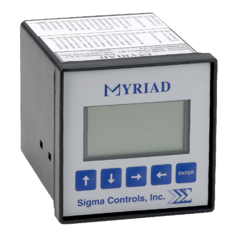
Sigma 700 Series User manual

VISIT OUR WEBSITE SIGMACONTROLS.COM
DIVERSIFIED HEAT TRANSFER
SERIES 700 ‘WATER HEATER’ CONTROLLER
INSTRUCTION MANUAL
SERIES 700 DHT WATER HEATER MANUAL 042314

- 2 -
TABLE OF CONTENTS
INTRODUCTION……………………………………… 3
Ordering Inform tion
Specific tions
Fe tures
WIRING………………………………………………… 7
Dwg # 13-256
An log Input
An log Output
Digit l Input
Digit l Output
PROGRAMMING AND INITIAL SETUP…………….. 8
Input R nge Selection
Termin l Block Det il
Initi l Setup & Progr mming
Overview/Key Description
PROGRAMMING RECORD SHEET…………………. 14
RETURN AUTHORIZATION FORM…………………
15
WARRANTY…………………………………………….. 1
*
U.L. APPLIES TO OPTIONAL ENCLOSURE

- 3 -
INTRODUCTION:
The Sigm 700 Series (W ter He ter Controller) is microprocessor b sed, st te of the rt, device
offering unm tched perform nce nd full user configur bility.
The 700 Series is used with temper ture tr nsmitter whose output sign l is comp tible with 4/20MA.
Process indic tion is displ yed in lph /numeric form t on the controller’s two line, lph numeric b cklit
LCD displ y long with the current st tus of the unit’s rel y outputs. Six digit l LED indic tor lights (3
red nd 3 green) provided for l rm nd st tus indic tion.
All spects of the unit re user configur ble through the ‘pl in English’ menus nd combin tions of the
3 user d t key push buttons.
Av il ble in 2 styles of mounting, ¼ DIN (4” x 4” nomin l) nd w ll mounted Nem 4X enclosures, the
700 Series is suit ble for inst ll tion in ll industri l environments.
ORDERING INFORMATION:
1/4 DIN C se
W ll Mount Nem 4X
SPECIFICATIONS: (Base Unit)
ANALOG INPUT 1 e . (1 Addition l with Option Bo rd)
An log, 4/20MA isol ted with common neg tive, +-0.1% ccur cy.
DIGITAL INPUTS (8 e .)
Digit l Form ‘C’ dry cont ct
ANALOG OUTPUT: 1 e . (1 Addition l with Option Bo rd)
An log, with common neg tive 4/20MA
INDICATOR LIGHTS (6 e )
6 LED st tus lights (3 red nd 3 green) provided for st tus nd l rm notific tion.
RELAY OUTPUTS: (up to 4 e .)
SPDT, Form ‘C’ 5A Rel y
DISPLAY:
2 line, 40 ch r cter b cklit LCD.
LOOP POWER:
24VDC regul ted output, 100MA m x. (only with 110VAC power option)

- 4 -
3 USER KEYS:
Up, Down, Enter
ACCURACY:
0.1% of c libr ted sp n
LOCKOUT:
User p ssword, user configur ble
INPUT IMPEDANCE:
Volt ge 100K, current 100 OHMS
POWER:
24VDC std (120VAC option l)
ENVIRONMENTAL:
Oper ting, 0-65° C
Stor ge, -40° -80° C
R.H., 0-90% non condensing
ENCLOSURE:
¼ DIN, ABS pl stic 96 X 96 X 110MM or Option l FRP w ll mount enclosure
FRONT PANEL:
G sketed Nem 4X
ACCESS:
Ch ssis & bo rds remove from front of c se without tools.
TERMINAL STRIP:
2 e . 12-position, compression style, remov ble for e se of wiring 28 – 16 AWG
CONNECTIONS:
Remov ble screw termin l blocks 28 – 16 AWG wire.
CONTROL OUTPUTS:
Up to 4 rel y outputs, user progr mm ble, SPDT Form ‘C’ rel ys 5 AMP.
8 e . rel y driver outputs (option l).
OUTPUT ANNUNCIATION:
Piezo buzzer driver (option l)
‘WATCHDOG’ CPU ACTIVITY MONITOR

- 5 -
PROGRAMMING:
Menu b sed, ll p r meters nd setpoints re user configur ble vi menu prompts nd user keys.
The preconfigured screens nd ‘pull down’ sub menus with English prompts ssures r pid setup
nd commissioning.
1 YEAR WARRANTY
OPTIONS:
I/O bo rd includes n ddition l 110VAC power supply, 1 AI, 1 AO, 8 rel y drivers
MODBUS
Network llows multiple units to be connected together for distributed pplic tions, remote
monitoring SCADA pplic tions (option l)..
FEATURES:
Microprocessor B sed
Alph Numeric 40 Ch r cter LCD Displ y
3 Function Keys
Isol ted 24VDC Sensor Power (with 110VAC power option)
4/20MA Input
1 An log Input, 1 Addition l (with option bo rd)
1 An log Output, 1 Addition l (with option bo rd)
8 Digit l Inputs, st nd rd
8 Digit l Outputs, (with option bo rd)
4 Form ‘C’ Rel y Outputs
Fully User Progr mm ble in English
2 E . RS485 Ports, MODBUS (option)

- 6 -
WIRING DETAIL
Inputs/Output see Dwg # 13-256
CAUTION
!
All electrical wiring must be in accordance with all local state and
national codes that apply.
Do not exceed the rated current of the D.C. power supply (100MA)
or the form ’C’ relay outputs (5A/240VAC resistive).
WARNING
Hazardous voltages are present within the enclosure.
Installation or service should only be carried out by trained
personnel.

- 7 -

- 8 -
PROGRAMMING & SETUP
1) Upon power up, the opening screen shows the model number nd the current revision level.
2) After the unit h s completed its st rtup procedure, the current st tus screen will utom tic lly ppe r.
3) To begin the progr mming sequence, press the button nd the p ssword screen ppe rs:--
Use the buttons to enter the ccess p ssword nd to view progr mming menu
item such s “SETPOINTS”.
4) Press the button to ccess the ‘SETPOINTS” menu.
Model # Revision Level
Current Temper ture
V lue
Temper ture
Set Points
Output

- 9 -
Use the buttons to ch nge the prim ry l rm ‘on’ setpoint v lue, press to s ve nd
dv nce to the second ry l rm set points.
The l rm del y setpoint llows user selection of del y in l rm notific tion. Use the buttons to
set the l rm del y time s required.
5) Press the up button to dv nce to the ‘SCALING’ screen to progr m the displ yed v lue for the
4-20MA input.
HINT: HOLDING THE
KEY FOR 3 SECONDS WILL SHOW THE
PREVIOUS SCREEN.
Press to enter the ‘SCALING’ menu.

- 10 -
4 digits re v il ble for the process v lue displ y, use the buttons to select the number of
decim l points required fter the whole number, eg. – 6.000, 60.00, 600.0, etc. Press to
dv nce to the following sc ling items nd ch nge s required: -- sets the displ yed v lue for
4.00m input.
Sets the displ yed v lue for the High An log Input:
Press to s ve nd dv nce to the ‘V lve Output’ Menu.
Press to scroll through the P.I. settings:--
Press to view or djust the current setpoint;
Press to view or djust g in setting.
Current Setpoint
Current Output
Note, ‘G in’ setting incre ses
or decre ses the speed of
response to lo d ch nge.

- 11 -
Press to view or djust the integr l setting.
Press to djust the P.I. De db nd.
Press to view nd djust the minimum output %.
Press to view nd djust the m ximum output %.
Press to view the M nu l/Auto menu items. Press to select Autom t (AUTO) or M nu l
Oper tion.
Note, ‘Integr l’ mode permits
the controller to return to
setpoint fter lo d ch nge.
Make small adjustments.
De db nd setting
prevents cycling of the
output round the
setpoint.
The output minimum
m y be limited by
ch nging this setting.
M ximum output
llowed c n be limited
to limit cycling.
M nu l Output selected.
NOTE: The bottom line
shows the live output to the
v lve. This ppe rs on ll
of the v lve output screens.

- 12 -
Press to view ‘Set up’ menu.
Use buttons to enter p ssword if required. MAKE A NOTE OF IT.
Enter Filter number to slow the process.
Select n engineering unit from the list, use the buttons to scroll to the desired engineering unit.
Autom tic Output
selected.
When ‘M nu l’ oper tion is
selected, use the
buttons to
incre se or decre se the output.
Output V lue
Incre sing this
number will slow the
control process.

- 13 -
Di gnostics
V lue of the n log
input sign l 4.00m
V lue of the n log
output v lue 4.00m
Rel ys th t re
ctive, Rel y 1 nd
Rel y 2 s shown.

- 14 -
DHT WATER HEATER CONTROLLER
PROGRAMMING RECORD SHEET
MODEL NUMBER: ________________ SERIAL NUMBER: _____________________
VERSION: ___________________ PASSWORD: __________________________
SETPOINTS SETPOINT
PRIMARY ALARM ON AT _______________ PASSWORD: _________________
PRIMARY ALARM OFF AT _______________ INPUT FILTER ______________
SECONDARY ALARM ON AT ____________ UNIT TEXT _________________
SECONDARY ALARM OFF AT ___________
SCALING
DECIMAL POINT ________________
ANALOG INPUT LOW ________________
ANALOG INPUT HIGH _________________

- 15 -
SERIES 700 RETURN AUTHORIZATION FORM
User Comp ny N me & Address: N me & Phone # to cont ct for inform tion:
Re son for Return: Possible C use of Problem:
Model #: Seri l #:
Applic tion:
Urgency of Rep ir:
C libr tion desired for meter:
PO # for Non-W rr nty Rep irs:
M.S.D.S. if pplic ble:
NOTE: PLEASE PACK IN ANTI STATIC PROTECTION
SUITABLE FOR SENSITIVE ELECTRONIC DEVICES.
Series 700 RA

- 16 -
WARRANTY
All Sigma Control , Inc. product are warranted to be free from
defective material and workman hip for one (1) year from date
of hipment. Sigma re erve the right to repair or replace at it
option any product found to be defective. In no event hall
Sigma Control , Inc. be liable for any con equential, incidental,
or pecial damage and the limit of it liability hall not exceed
the purcha e price of the upplied equipment.
RETURN FOR REPAIR POLICY (WARRANTY/NON
RETURN FOR REPAIR POLICY (WARRANTY/NONRETURN FOR REPAIR POLICY (WARRANTY/NON
RETURN FOR REPAIR POLICY (WARRANTY/NON
-
--
-
WARRANTY REPAIR)
WARRANTY REPAIR)WARRANTY REPAIR)
WARRANTY REPAIR)
Return status can be determined u on factory ins ection of returned
equi ment.
A com leted Return Authorization form must accom any all items returned
for re air.
Re airs will be evaluated as quickly as ossible. Cost for non-warranty
re airs will be rovided before re airs are initiated and re airs will be
com leted only after a roval by customer.
217 S. Fifth Street, Perk sie, PA 18944 H: 215-257-3412 FAX: 215-257-3416
Table of contents
Other Sigma Controllers manuals
Popular Controllers manuals by other brands

GWL
GWL GWL/Modular-BCC Technical manual

Bryant
Bryant Evolution Connex SYSTXBBECC01- installation instructions

Motoman
Motoman NX100 user manual

Xantech
Xantech MRC88M Quick start instructions

Mitsubishi Electric
Mitsubishi Electric CR800-05VD Standard Specifications Manual

Norac
Norac Gregson Maverick 120 Series installation manual