Aseptico COMMAND-AIR ALU-29CF User manual

ALU-29CF
Portable Light
NSN: 6520-01-446-4170
OPERATION / MAINTENANCE
MANUAL & PARTS LIST
COMMANDlAIR

Page 2
TABLE OF CONTENTS
Introduction . . . . . . . . . . . . . . . . . . . . . . . . . . . . . . . . . . . . . . . . . . . . . . . . . . . . . . . . . . . . . . . .3
Purpose . . . . . . . . . . . . . . . . . . . . . . . . . . . . . . . . . . . . . . . . . . . . . . . . . . . . . . . . . . . . .3
Performance Characteristics . . . . . . . . . . . . . . . . . . . . . . . . . . . . . . . . . . . . . . . . . . . .3
Items Furnished . . . . . . . . . . . . . . . . . . . . . . . . . . . . . . . . . . . . . . . . . . . . . . . . . . . . . .3
Oper tion Instructions . . . . . . . . . . . . . . . . . . . . . . . . . . . . . . . . . . . . . . . . . . . . . . . . . . . . . . .3
Set-Up . . . . . . . . . . . . . . . . . . . . . . . . . . . . . . . . . . . . . . . . . . . . . . . . . . . . . . . . . . . . . .3
Lamp Controls . . . . . . . . . . . . . . . . . . . . . . . . . . . . . . . . . . . . . . . . . . . . . . . . . . . . . . .4
M inten nce . . . . . . . . . . . . . . . . . . . . . . . . . . . . . . . . . . . . . . . . . . . . . . . . . . . . . . . . . . . . . . .4
Lamp Replacement . . . . . . . . . . . . . . . . . . . . . . . . . . . . . . . . . . . . . . . . . . . . . . . . . . .4
Changing the Fuse . . . . . . . . . . . . . . . . . . . . . . . . . . . . . . . . . . . . . . . . . . . . . . . . . . . .5
Troubleshooting . . . . . . . . . . . . . . . . . . . . . . . . . . . . . . . . . . . . . . . . . . . . . . . . . . . . . . . . . . . . .4
P rts Di gr m . . . . . . . . . . . . . . . . . . . . . . . . . . . . . . . . . . . . . . . . . . . . . . . . . . . . . . . . . . . . . .6
P rts List . . . . . . . . . . . . . . . . . . . . . . . . . . . . . . . . . . . . . . . . . . . . . . . . . . . . . . . . . . . . . . . . . .7
TABLE OF ILLUSTRATIONS
Figure 1 - Setup . . . . . . . . . . . . . . . . . . . . . . . . . . . . . . . . . . . . . . . . . . . . . . . . . . . . . . . . . . . . .3
Figure 2 - Fuse Replacement . . . . . . . . . . . . . . . . . . . . . . . . . . . . . . . . . . . . . . . . . . . . . . . . . .5
Figure 3 - Parts Diagram . . . . . . . . . . . . . . . . . . . . . . . . . . . . . . . . . . . . . . . . . . . . . . . . . . . . .6

Page 3
PERFORMANCE CHARACTERISTICS:
LAMP: FTB 20watt/12volt 10°
LAMP LIFE: 2000 hrs. average life.
HEIGHT: 36-64 inches
ARM LENGTH: 32 inches
VOLTAGE: 110-220VAC, 50/60Hz switchable
LIGHT INTENSITY: 1,000 ft. candles at 24” (61 cm)
WEIGHT: 15 lbs.
ITEMS FURNISHED
One (1) ALU-29CF Command Air Portable Light
One (1) Soft padded carrying case
One (1) Operation and Maintenance Manual
One (1) Spare Halogen bulb
One (1) 160mA Fuse (for 220V operation)
One Each 110V & 220V Power Cord
PURPOSE:
The Aseptico ALU-29CF Command Air Portable Light contains a halogen operating light which
provides brilliant white light ensuring excellent visibility for field dentistry. The dual-voltage
ALU-29CF features a compact lamp head, flexible gooseneck, telescoping tripod stand and
padded carrying case. This light is highly portable and will fit in the mil-spec hard shell case
included with the ADC-01CS Command Air Portable Dental Chair for easy deployment.
SETUP (Fi . 1):
1. Remove the ALU-29CF Light from its packing and
carrying case. Unfold the tripod legs to a horizontal
position, slide to the bottom of the center post, and
secure in position by firmly tightening the thumb screw.
Set light on a stable, even floor surface.
2. Loosen knob on horizontal boom and position where
desired. Tighten to set. Rotate handle counterclockwise
on telescoping center column and adjust to desired
operating height. Rotate clockwise to secure.
3. Ensure that the correct fuse is installed for the power
source used (refer to Changing Fuse, Page 5). Set the
dual voltage switch to 110V for 110-120V 50/60 Hz
power sources and to 220V for 220V 50/60 Hz power
sources. Attach power cord to receptacle on bottom of
electrical housing and plug cord into a grounded
electrical outlet. NOTE: USA style 110V and 220V
power cords are shipped with unit. Power plug adapters
for the specific country of usage must be purchased
separately.
BRIGHTNESS
KNOB
DUAL VOLTAGE
SWITCH
POWER
SWITCH
POWER CORD
POWER CORD
RECEPTACLE
& FUSE HOLDER
LENS/FILTER
COVER & GUARD
LIGHT BOOM
ADJUSTABLE
CENTER COLUMN
Figure 1 - Setup

Page 4
MAINTENANCE:
LAMP REPLACEMENT
Step 1 - Remo e Guard Assembly:
1. Grasp the Guard Assembly as shown. Unscrew (turn
CCW) to remove Guard from Rear Casing and set
aside. Do not touch the Lens - fingerprints on the Lens
surface will attenuate the light beam. Do not remove
the two retaining clips and screws which attach the
Lens and O-ring to the Guard.
Step 2 - Unco er Lamp:
1. Grasp the Heat Shield Tube as shown and gently screw
inwards (turn CW) until it makes contact with the
inside surface of the Rear Casing. IMPORTANT:Stop
turning when the Shield Tube first touches the Rear
Casing - forcing it beyond the “contact point” could
result in damage to Disk and Lamp Socket!
Step 3 - Remo e Lamp:
1. Carefully grasp the exposed edge of the Lamp reflector
and gently pull the Lamp straight out of the socket -
keep Lamp centered in the Shield as you pull.
WARNING: Do not touch the glass bulb portion of the
halogen Lamp. Oils left by finger contact can cause the
glass to bubble and possibly explode.
2. Discard the old Lamp. CAUTION: To prevent injury
from broken glass, wrap the Lamp in heavy paper or
cardboard, or secure in a container before discarding.
Step 4 - Install New Lamp:
1. When installing the replacement Lamp, ensure that its
pins align with the socket receptacles, which are
accessible through the opening in the Heat Shield Disk.
Carefully press the pins straight into the receptacles
until the base of the Lamp is firmly seated against the
Disk. If the Lamp pins are properly aligned, the Lamp
will seat easily. CAUTION: Do not press hard on Lamp -
it could break and cause injury. NOTE: The pin
receptacles are offset at a slight angle. Do not twist the
Lamp when inserting into socket - pins could bend and
damage Lamp and socket.
Repl cement L mp: Use only USHIO 20MR11 20watt/
12volt. Use of any other lamp may degrade the operation
of the ALU-29CF and/or cause a safety hazard.
Step 1- Remove Guard
Step 2 - Uncover Lamp
Step 3 - Remove Lamp
Step 4 - In tall New Lamp
CW
LAMP CONTROLS:
1. POWER SWITCH - On/Off control of ALU-29CF Light. Lamp should illuminate when turned on.
2. BRIGHTNESS KNOB - Provides variable intensity control of lamp. Turn clockwise to increase lamp intensity,
or counterclockwise to decrease intensity.
3. DUAL VOLTAGE SWITCH - Allows this light to be used with either 110 or 220 VAC power sources. Rotate
switch to the proper voltage-source position.
IMPORTANT: Turn power off nd unplug ALU-29CF from
power source before repl cing l mp. Prior to handling unit,
allow Lamp Head and internal components to cool for sev-
eral minutes to room temperature.
REAR
CASING GUARD
ASSEMBLY
HEAT SHIELD TUBE
LAMP
HEAT
SHIELD
TUBE
LAMP
SOCKET
RECEPTACLE
HEAT SHIELD
DISK

Page 5
WARNING: Do not turn the halogen Lamp ‘On’
without the Guard/Lens Assembly installed. The
Lamp emits harmful UV radiation and damage to
eyes and skin could result if Assembly Lens (UV
Filter) is not in place.
WARNING: Halogen bulb is HOT ! Operating the
Lamp without the Guard installed can cause burns!
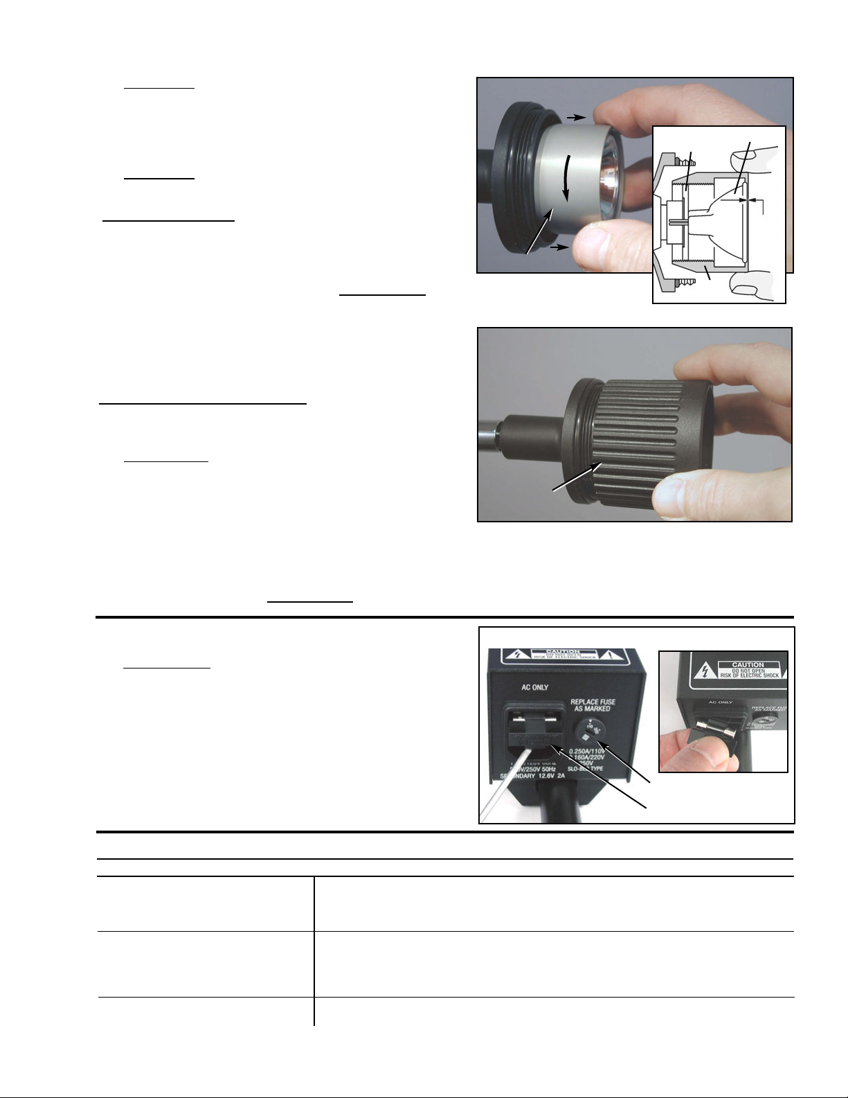
Step 5 - Co er Lamp:
1. Retract (turn CCW) the Heat Shield Tube away from
the Rear Casing to enclose the Lamp. Back the Tube
out until its forward lip protrudes approx. 0.075 inch
beyond the front edge of the Lamp. IMPORTANT:
Not retracting the Shield Tube forward may cause the
Lamp to come in contact with the glass Lens on the
Guard Assembly. Ensure that the Lamp reflector is
centered within the Shield and does not contact any
part of the Shield Tube or glass Lens on the Guard.
Step 6 - Replace Guard Assembly:
1. Grasp the Guard Assembly as indicated and carefully
match screw threads with those on the Rear Casing.
IMPORTANT: Do not touch or apply pressure on the
front surface of the Guard Assembly Lens. Fingerprints
left on the Lens will attenuate the light beam. Do not
remove the two retaining clips and screws which attach
the Lens and O-ring to the Guard.
Install (turn CW) Guard Assembly onto the Casing. If
the Guard does not easily screw onto the Casing, the
threads are likely misaligned - Do Not Force! Back the
Guard off and try again. IMPORTANT: When the
Guard Assembly Lens comes in contact with the Heat
Shield Tube, stop tightening! Damage to Lens and
other internal components may occur if overtightened.
Step 5 - Cover Lamp
Step 6 - Replace Guard
CCW
Problem:
Power is 'ON', but lamp does not
light:
Light intensity appears dimmer
than normal:
Blown fuse:
Correction:
-Replace Fuse: 5 x 20mm 250 mA (for 110V), or 5x20mm 160 mA (for 220V)
-Replace Lamp.
-Check plug and electrical source.
-Turn intensity up.
-Check that voltage switch matches power source
-Clean Lens (Note: Before cleaning, turn Unit ‘Off’ and allow to cool. Do not
remove the retaining clips and screws which attach the Lens to the Guard)
-Check that Lamp pins are straight and are not bent. (Bent pins can cause a
short circuit and blow the fuse if they make contact with the Heat Shield Disk.)
TROUBLESHOOTING:
HEAT SHIELD TUBE
GUARD
ASSEMBLY
0.05”
TO
0.10”
HEAT
SHIELD
LAMP
CHANGING THE FUSE (Fig. 2)
1. IMPORTANT: Turn ALU-29CF Power Switch ‘Off’
nd unplug unit from power outlet before ch nging
the fuse. Use a slot-head screwdriver to pry the
Fuseholder out of the Power Inlet Connector, located
on bottom of the electrical housing. Install new fuse
(see type below) and replace holder in Connector,
applying pressure on holder until it firmly snaps into
position. Set Dual Voltage Switch to proper voltage.
110VAC FUSE: 5x20mm 250 mA, slo-blo type
220/250VAC FUSE: 5x20mm 160 mA, slo-blo type
Figure 2 - Fu e Replacement
FUSEHOLDER
DUAL VOLTAGE SWITCH
HEAT SHIELD
DISK

Page 6
Aseptico ALU-29CF
Command Air Portable Li ht
Figure 3 - Part Diagram
PCB Assembly
16
12
26
28
10
11
15
17
13
24
23
25
30
29
1
2
5
6
19
21
14
18
8
9
3
7
4
22
27
31
33
34
20
21
22
28
32

PARTS LIST
Lamp Head, Guard & Lens Assy w/Clips 820002 1
Lamp, FTB 20watt/12volt 10° 820001 1
Heat Shield Tube 461355-08 1
Heat Shield Disk 461356-08 1
SMS Stnls PhdPhl 10x3/4 510305 4
O-Ring, 2.0 OD x 0.093 520045 1
Socket, Porcelain 820025 1
Adapter, Goose-neck/Lamp 460257-08 1
Goose-neck, 13” Black 730084 1
Adapter, Boom/Goose-neck 460258-08 1
Boom, Complete 460259-01 1
Strain Relief, 1/4 Black 840048 1
Nut, T-Bar Torque Handle 510381 1
Cable, 2-Conductor Coil 870225 1
Strain Relief, Flex 840003 1
Chassis, Top 460660-08 1
C/S BtnSoc Stnls 6-32x1/4 510037 4
nob, 1/4 Blk w/ Gray Insert 850032 1
Pot, 100 Linear 810123 1
Switch, Rocker SPST 830002 1
Voltage Selector Switch 840042 1
Power Inlet , Fused Snap In 840035 1
Fuse, 5x20mm 250 mA (for 110V) 830049 2
Fuse, 5x20mm 160 mA (for 220V) 830046 1
Capacitor, 100V, 0.22MFD 810108 1
Transistor, R6004LT Triac 880037 1
Resistor, 1/4 w 5% 1.0 810006 1
PCB, ALU-29CF 550043 1
Transformer, 115/230V 13.6V, 2A 800100 1
Chassis, Base 460661-08 1
Bracket, Nylon Mounting 460329 1
Stand, Black Folding Tripod 730252-08 1
Line cord, Remote 110V 840008 1
Line cord, Remote 220V 840007 1
Not Shown Case, Gray Carrying 410125 1
Not Shown Resistor, 1/4 w 5% 100 810008 1
Page 7
Item Part Number Quantity
13
27
29
11
12
16
18
14
25
26
30
1
3
2
6
7
15
9
10
4
8
5
28
24
31
21
20
22
19
17
23
32
33
34

P/N 420305
Rev.
ECO 12715
11/2011
P.O. B x 1548 W dinville, WA 98072-1548
1-800-426-5913 • 425-487-3157 • Fax: 360-668-8722
email: inf @aseptic .c m • Internet: www.aseptic .c m
WARRANTY
Aseptico warrants its products against defects in material or workmanship for a period
of two (2) years, from date of original in oice. Some handpieces are warranted for
one year under the same conditions. Other handpieces and expendable
components, such as air turbines and light bulbs, are co ered by shorter warranty
periods, or ha e no warranty. Aseptico's sole obligation under product warranty is (at
its sole option and discretion) to repair or replace any defecti e component or product
in part or whole. Aseptico shall be the sole arbiter of such action.
In the e ent of alleged defect under warranty, the purchaser is to notify Aseptico's
Customer Ser ice Department promptly. Customer Ser ice will pro ide instructions,
usually directing that the product be returned for ser ice. Shipment to Aseptico and
the cost thereof is always the responsibility of the purchaser.
Accidental misuse, inappropriate installation, or failure to perform directed
maintenance oids the warranty.
Aseptico does not assume, under this warranty, any risks or liabilities arising from the
clinical use of its products, whether or not such use in ol es coincidental utilization of
products manufactured by others.
Table of contents
Popular Work Light manuals by other brands

UNILITE
UNILITE ANSI FL1 Standard quick start guide

Feit Electric
Feit Electric MOON1/RGBW/LED Important Safety Instructions and Installation Guide

brennenstuhl
brennenstuhl HL 0400 A operating instructions

Bayco
Bayco 623 instructions

Spectroline
Spectroline NANO 365 Series quick start guide

NORDRIDE
NORDRIDE LINE LIGHT operating instructions