ASG X-PAQ ASG-NW2500-EIP User manual

ASG-NW2500-EIP
Ethernet IP Network Communication
Module
ASG Precision Fastening ASG NW2500-EIP
User’s Guide
Version 1.0.0
Major Revision:December, 2010
To download the latest version of this manual visit:
www.asgprecisionfastening.com
ASG Precision Fastening
15700 S. Waterloo Rd Cleveland, Ohio 44110 www.asgprecisionfastening.com
216-486-6163 Toll free: 888-486-6163 Fax 216-481-4519
©2010 Jergens Inc.
All Rights Reserved
1 aqwirelessEIP.pub

Table of Contents:
Safety Precautions 3
Installation 4
Quick Start 6
Overview 7
Human Machine Interface 7
Network Connector 7
Serial Port 7
Operating Mode 7
Programming
Navigating the Program Menu 8
IP Address 8
Subnet Mask 9
Gateway 10
Connection Type (Static/Dynamic) 10
Data Output 11
Data Input 13
Data Masks 15
Setting New Password 15
Connection Status 15
2

Safety Precautions
Be sure to read all instructions and precautions contained in this manual,
failure to do so may result in personal injury and/or damage to tooling and
components.
Do not operate or plug in the controller/system with wet hands or in wet envi-
ronments. Failure to observe this may result in injury due to electric shock.
Ensure the controller is properly plugged in to a grounded electrical recepta-
cle. Do not remove the ground pin or use any adapter plugs.
Always shut down the controller when changing cables or tools. Failure to do
so could damage the tool or controller.
Keep work area clear of clutter and distractions that may cause the operator to
lose control of the tool or the components.
Tool cable must be properly routed and festooned to avoid tangling and trip
hazards.
Always use safety glasses when using electrical assembly tools.
Do not use any part of the system (tool, cable, or controller) for anything other
than its specified application. Use of the system or its components for unin-
tended applications could result in injury to the operator, failure of the system,
and could void the warranty.
Never modify or disassemble any component of the system. Modification or
disassembly of the system could result in injury and void the warranty.
3

4
Installation
Ensure power is off to the CT2500 controller and unplug the power cable.
Remove NW2500 Module from its packaging, and locate the Network Module In-
put Plug on the bottom of the module.
Align the Network Module Input Port to the mating connector on the top of the
CT2500 controller.
Tighten (4) captive screws to secure the Network Module to the Controller.
Network Module
Input port
Tighten (4)
Screws

5
Installation Continued.
Reconnect power to the CT2500 Controller, and then turn on the power to the
Controller.
Verify the Network Module powers up properly by looking to see if the Network
Module Display is lit and has its IP address displayed.

6
Quick Start Guide:
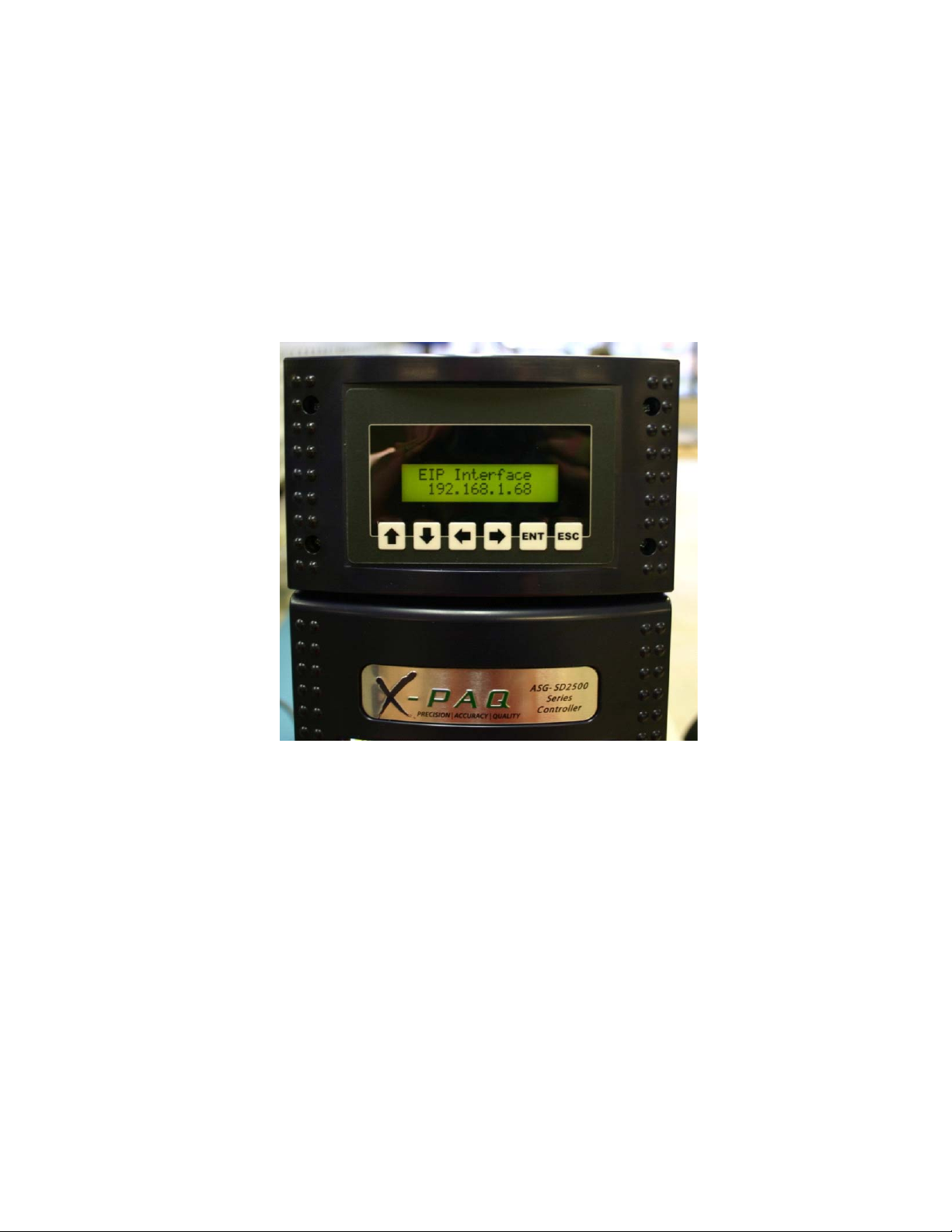
Step 1: Power up the NW2500-EIP.
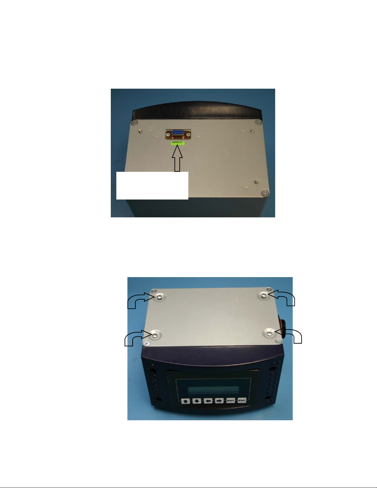
Step 2: Be sure that the unit is physically connected to the network through the
Ethernet connection (RJ45 Connector).
Step 3:
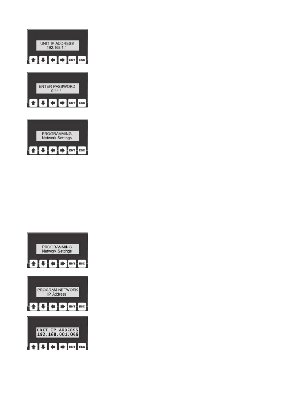
Use the network user interface and enter the program mode by
pressing the ENT key. The unit will prompt the user for a password at
this point, the default is “0 1 0 4”. Using the keypad, enter the pass-
word
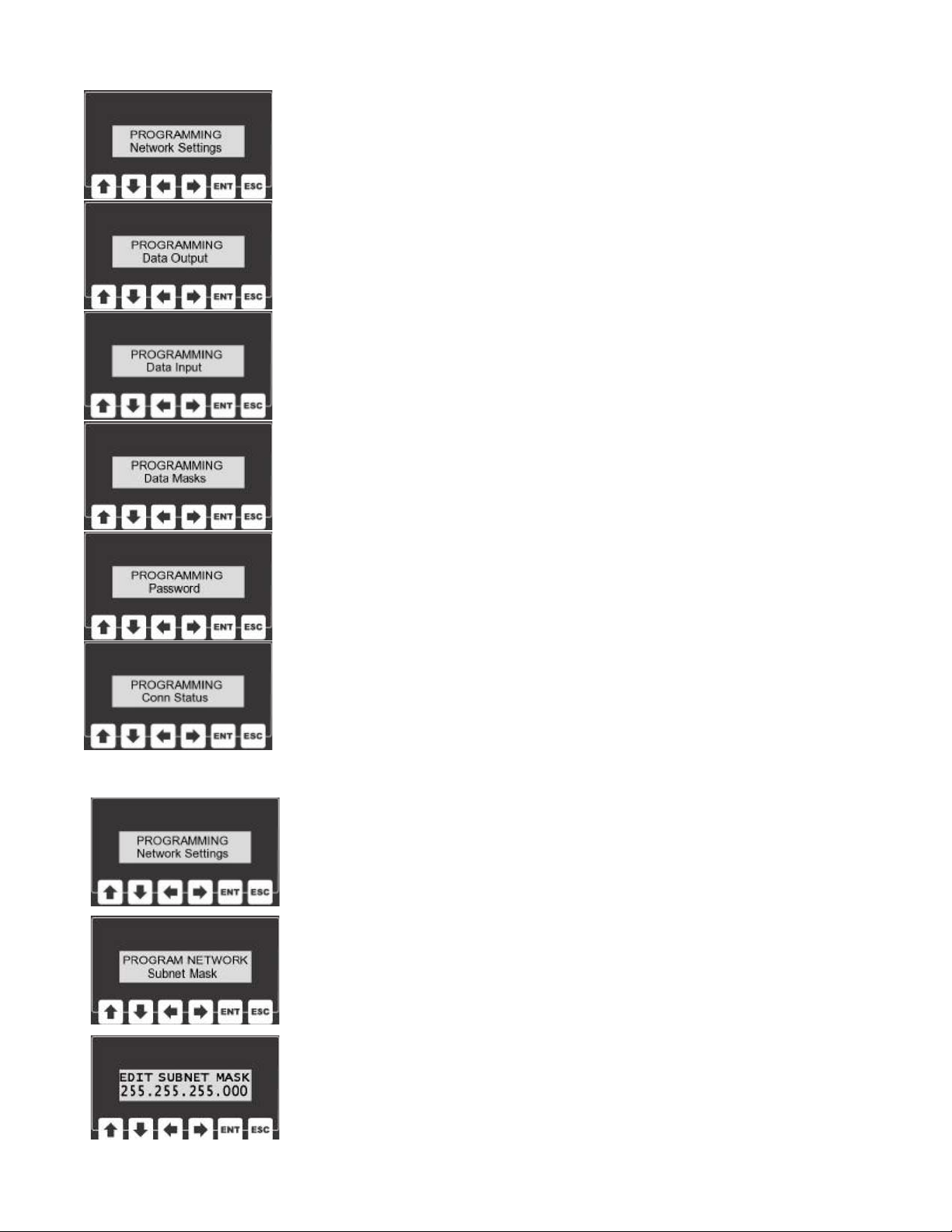
Step 4 Network Settings:
The menu system is broken down into a few different sub-menus.
Select “Network Settings” from the main menu and press the ENT
key.
Step 5 Connection Type:
The the “Network Settings” sub-menu select “Connection” and press
the ENT key. The connection type can be set to either static or dy-
namic. If dynamic is chose, the network should automatically select
an IP address. If static is chose, an IP address will need to be pro-
grammed into the unit.
Step 6 Set IP Address:
This step can be skipped if IP addresses are assigned dynamically by
the network. If the connection type is static, select “IP Address” from
the sub-menu and press the ENT key. Using the arrow keys, edit the
IP address for the unit. Please consult the IT director for this value.
Step 7 Subnet Mask:
Next, from the networking sub-menu, select “Subnet Mask”. The Sub-
net Mask helps the unit determine which IP addresses are local and
which lie beyond a Gateway. Press the ENT key to view the unit’s
Subnet Mask. Using the arrow keys alter this setting to the desired
value (please consult your IT group for this value). Press the ENT key
to store the value.
Step 8 Gateway:
The Gateway setting holds the address of the device that will allow
this unit to send and receive messages with devices that are not on
the local network. Press the ENT key to view the unit’s Gateway ad-
dress. Using the arrow keys alter this setting to the desired value
(please consult your IT group for this value). Press the ENT key to store the value.
Step 9 Cycle Unit Power:
After all of the network settings are programmed. Turn the unit off and then back on again.
The network module’s settings will only be altered at power up.

7
Overview:
The AQ wireless can be equipped with a network card that provides connectivity to a
Plant Floor Control System using Ethernet IP. This interface includes a network
card, a human-machine interface (LCD display & keypad), an additional serial port,
and an RJ45 network connector.
Human-Machine Interface:
The human machine interface (HMI) consists of an 2-line by 16
character backlit LCD display and a six button keypad. During
power-up, the display on the HMI will display the firmware ver-
sion contained inside the microprocessor’s memory.
During operation, the HMI will show the unit’s IP address.
The HMI is also used during the programming phase allowing
the user to enter program menus. These program menus allow access to settings
that govern how the Ethernet IP interface functions.
Network Connector (RJ45):
The Ethernet port is used to transmit and receive TCP/IP messages that are format-
ted to comply with Ethernet IP.
Serial Port (MIF):
The additional serial port on this unit is a debugging port. This
port will give the user direct access to the network module. A ter-
minal program is all that is necessary to use this port. The set-
tings for the terminal program should be 38400 baud, 8-bit, no-
parity, and 1 stop bit.
Operating Mode:
When the Ethernet IP network interface powers up, the display
briefly shows the firmware version information and then the
unit enters it’s operating mode.
In the main operating mode, the display will show the unit’s IP
address. From this main screen the user can press the ENT key
to enter the programming mode.
DSUB 9 PINOUT
2 - RX
3 - TX
5 - GND

8
Program Mode:
There are several items that are user configurable through the
programming menu. In order to reach this menu from the main
display, press the enter (ENT) key.
The display will prompt the user to enter a password before
reaching the programming menu. The default password is “0 1
0 4”.
While entering the password, the left and right arrow keys will
move the cursor back and forth. The up and down arrows will
raise and lower the value of the digit that the cursor is high-
lighting.
The escape key (ESC) will send the program back to the main screen without at-
tempting to read the password. If the enter key (ENT) is pressed, the unit will com-
pare the entered password to the password that is stored in the unit’s non-volatile
memory. If these values match, the unit will continue onto the programming menu.
Programming the Unit’s IP Address:
It’s important that each device on the network has it’s own unique IP
address. In order to edit this interface’s IP address, select Program-
ming IP Address from the main menu and press enter.
The current IP address will be displayed at this point. In order to
change the address use the LEFT and RIGHT arrow keys to select any
given digit in the address and then use the UP and DOWN keys to al-
ter that digit’s value.
Once the desired IP address is displayed, the enter key can be
pressed to save that value. All programmable values are stored in
non-volatile memory. This allows the unit to “remember” these values
even when the unit is turned off and unplugged. The escape key can
be pressed any time during the editing process allowing the user to
return to the main menu without saving a new value. For a new IP
address to take effect, the unit’s power must be cycled off and then
back on.

9
Programming Menu:
The Ethernet IP network card has quite a bit of flexibility and there-
fore also has a large number of variables that can be programmed by
an end user.
The menu system has been broken down into several logical sub-
menus.
The network sub-menu contains IP addresses, gateway and subnet
mask configurations.
The data input and data output menus allow user to select which
data bytes to send/receive and also where those bytes will be located
in the input and output strings.
The data mask sub-menu allows users to choose different popular
data masks that include different input and output data.
The password can be edited from this menu and the connection
status can also be monitored
Programming the Unit’s Subnet Mask:
The Subnet Mask is used to identify which part of the IP ad-
dress is the network ID and which part is the host ID. This is
accomplished by a logical bitwise ANDing of the IP address and
the netmask. In order to edit the netmask, select Subnet Mask
from the main menu and press enter.
The current mask value will be displayed at this point. In order
to change the mask’s value use the LEFT and RIGHT arrow
keys to select any given digit in the address and then use the
UP and DOWN keys to alter that digit’s value. Pressing the en-
ter key will allow the user to save the new subnet mask that is
displayed on the LCD. The escape key can be pressed any time
during the editing process allowing the user to return to the
main menu without saving a new value. For a new Subnet
Mask to take effect, the unit’s power must be cycled off and
then back on.

10
Programming the Gateway:
Gateways perform routing functions. This gateway value identi-
fies the router that connects a LAN to other networks. Some
gateways also perform protocol conversions.
In order to edit this gateway’s IP address, select Gateway from
the main menu and press enter.
The current gateway address will be displayed at this point. In
order to change the address use the LEFT and RIGHT arrow
keys to select any given digit in the address and then use the
UP and DOWN keys to alter that digit’s value.
Pressing the enter key will allow the user to save the gateway’s IP address that is
displayed on the LCD. The escape key can be pressed any time during the editing
process allowing the user to return to the main menu without saving a new value.
For a new Gateway to take effect, the unit’s power must be cycled off and then back
on.
Programming the Connection Type:
The IP Address assigned to this unit.
The current timeout value (in seconds) will be displayed at this point.
In order to change the value the arrow keys may be pressed. The UP
key will add one second, DOWN will subtract a second, RIGHT will
add 10 seconds, and LEFT will subtract 10 seconds from the value.
Pressing the enter key will allow the user to save the value that is dis-
played on the LCD. The escape key can be pressed any time during
the editing process allowing the user to return to the main menu
without saving.

11
Data Output:
This unit is capable of transmitting 103 output bytes. The user can
select which groups of information are actually transmitted.
Output Data # of Bytes Default
Location
Parameter 1 0
Tool Type 3 1
Tool Name 8 4
OK/NOK 1 12
Result 1 13
Count 1 14
Batch 1 15
Rolling Count 2 16
Total 2 18
Time 6 20
Date 6 26
EE Write Time 6 32
EE Write Date 6 38
Torque 6 44
Min Torque 6 50
Max Torque 6 56
Units 1 62
Angle 5 63
Min Angle 5 68
Max Angle 5 73
Tool Type A 3 78
Tool Type B 3 81
Tool Type C 3 84
Tool Type D 3 87
Tool Type E 3 90
Tool Type F 3 93
Tool Type G 3 96
Tool Type H 3 99

12
Data Output (continued):
Output Data Description
Parameter ASCII character representing current parameter. Possible values
A’ (0x41) through ‘H’ (0x48).
Tool Type Three ASCII characters describing the tool type. Possible values
include ‘DIG’, ‘CLK’, ‘AIR’, and/or ‘BAT’
Tool Name Up to 8 alpha-numeric ASCII characters that represent a user defined
tool name.
OK/NOK Single character giving status of last fastening. ‘O’ (0x4F) for okay or ‘N’
(0x4E) for not okay.
Result Single character giving status of last fastening. ‘C’ (0x43) for cycle,
‘B’(0x42) for batch and ‘R’ (0x52) for reject.
Count Number of fasteners completed towards the batch. Possible values 0x00
through 0xFF.
Batch Value representing the number of fasteners in a batch. Possible values
0x00 through 0xFF.
Rolling Count Integer (2 bytes) holding a rolling count. The count will increase with
each new result. Possible value 0x0000 through 0xFFFF.
Total Integer (2 bytes) representing number of batches completed in a given
parameter. Possible value 0x0000 through 0xFFFF.
Time 6 ASCII bytes describing the time an event occurred in HHMMSS
format.
Date 6 ASCII bytes describing the date an event occurred in MMDDYY
format.
EE Write Time 6 ASCII bytes describing the last time the eeprom was written to in
HHMMSS format.
EE Write Date 6 ASCII bytes describing the last date the eeprom was written to in
MMDDYY format.
Torque 6 ASCII numbers and/or decimal point representing the torque value
from the last fastening (if available).
Min Torque 6 ASCII numbers and/or decimal point representing the min torque
setting from the last fastening (if available).
Max Torque 6 ASCII numbers and/or decimal point representing the max torque
setting from the last fastening (if available).
Units Single character describing torque units used during last fasting.
Possible values ‘I’/InLB, ‘N’/Nm, ‘F/FtLb, ‘K’/KgCm, and ‘m’/mKg.
Angle 5 ASCII numerals representing angle.
Min Angle 5 ASCII numerals representing min angle setting.
Max Angle 5 ASCII numerals representing max angle setting.
Tool Type A Three ASCII characters describing the tool type in parameter A.
Tool Type B Three ASCII characters describing the tool type in parameter B.
Tool Type C Three ASCII characters describing the tool type in parameter C.
Tool Type D Three ASCII characters describing the tool type in parameter D.
Tool Type E Three ASCII characters describing the tool type in parameter E.
Tool Type F Three ASCII characters describing the tool type in parameter F.
Tool Type G Three ASCII characters describing the tool type in parameter G.
Tool Type H Three ASCII characters describing the tool type in parameter H.
.

Programming Data Output:
The user has the ability to decide the total number of bytes this unit
with transmit as output bytes. The user can also decide which ele-
ments of output data will be transmitted and at what address.
To set the number of output bytes, the user will want to select Num
Output Bytes from the Data Output submenu. After pressing the ENT
key, the user can use the arrow keys to set the number of output
bytes. Pressing ENT will save this value ESC will allow the user to exit
without saving a new value.
Similarly, each piece of output data can be located wherever the user desires in the output
message. To program any of the output data, select it from the data output sub-menu.
When the ENT key is pressed, the address of where the first byte will be placed will be
shown. The user can use the arrow keys to manipulate this value and set it to any desired
address or to DONOT SEND. Once the desired value is displayed, pressing ENT will store
that value. The ESC key can be pressed to exit without saving
This unit is capable of receiving 40 input bytes. The user can select
which groups of information are actually received.
Data Input
Input Data # of Bytes Default Location
Parameter 1 0
Batch Reset 1 1
Suspend 1 2
Batch Value 1 3
Time 6 4
Date 6 10
Torque Min 6 16
Torque Max 6 22
Angle Min 5 28
Angle Max 5 33
Units 1 38
13

14
Data Input Continued
Input Data Number of Bytes
Parameter Changing this byte will alter the parameter setting in the unit. Possible
value ‘0’ through ‘7’, 0 through 7, and ‘A’ through ‘H’.
Batch Reset Setting this byte to a non-zero value will reset the batch count.
Suspend Setting this byte to a non-zero value will suspend the unit. Set byte back
to zero to un-suspend.
Batch Value Altering this byte will reprogram the batch value in the current
parameter. If this value is zero, no action will be taken.
Time Altering this value will reprogram the current unit time with these 6
bytes. HHMMSS format. Both time and date must be legal values for
write to occur.
Date Altering this value will reprogram the current unit date with these 6
bytes. MMDDYY format. Both time and date must be legal values for
write to occur.
Torque Min Altering these 6 bytes will change the min torque setting for the current
parameter. Min/Max Torque, Min/Max Angle, and Units must all be
legal value before write will occur.
Torque Max Altering these 6 bytes will change the max torque setting for the current
parameter. Min/Max Torque, Min/Max Angle, and Units must all be
legal value before write will occur.
Angle Min Altering these 5 bytes will change the min angle setting for the current
parameter. Min/Max Torque, Min/Max Angle, and Units must all be
legal value before write will occur.
Angle Max Altering these 5 bytes will change the max angle setting for the current
parameter. Min/Max Torque, Min/Max Angle, and Units must all be
legal value before write will occur.
Units Altering this bytes will change the units setting for the current
parameter.Possible values ‘I’/InLB, ‘N’/Nm, ‘F/FtLb, ‘K’/KgCm, and
‘m’/mKg. Min/Max Torque, Min/Max Angle, and Units must all be legal
value before write will occur.
Programming Data Input:
The user has the ability to decide the total number of bytes this unit
with receive as input bytes. The user can also decide which elements
of input data will be received and at what address.
To set the number of input bytes, the user will want to select Num In-
put Bytes from the Data Input sub-menu. After pressing the ENT key,
the user can use the arrow keys to set the number of input bytes.
Pressing ENT will save this value ESC will allow the user to exit with-
out saving a new value. Similarly, each piece of input data can be
located wherever the user desires in the input message. To program
any of the input data, select it from the data input sub-menu. When
the ENT key is pressed, the address of where the first byte will be read will be shown. The
user can use the arrow keys to manipulate this value and set it to any desired address or to
DO NOT SEND. Once the desired value is displayed, pressing ENT will store that value. The
ESC key can be pressed to exit without saving.

15
Programming Data Masks:
A few different automatically selectable data masks are resident in
memory. By selecting
one of these default masks, the user can set the input and output
data to one of several different defaults.
Default Mask: The default mask includes all of the input and output data. The addresses
are defined in the data input and data output sections of this manual. Selecting this value
will return the unit to it’s default data settings.
Mask 1: Mask 2:
Output Byte Location Input Byte Location Output Byte Location
Parameter 0 Parameter 0 OK/NOK 0
OK/NOK 1 Batch Reset 1 Rolling Count 1
Result 2 Suspend 2
Count 3 Batch 3
Batch 4
Rolling Count 5
Total 7
Mask 2 has no input bytes
All Off: The all off setting turns all of the incoming and outgoing data off. This is a great
place to start if the user only wants to send and receive a few bytes
Changing the Password:
In order to gain access to the programming menu, the user must en-
ter a password. The password is a four digit (numeric) code.
All units ship with a default code of “0 1 0 4”. This default code may
be changed to a value that is more easily remembered by the user.
In order to edit the password, select Edit Password from the program-
ming menu and press enter. To change the password use the LEFT
and RIGHT arrow keys to select any given digit in the address and
then use the UP and DOWN keys to alter that digit’s value. Pressing
the enter key will allow the user to save the new password. The es-
cape key can be pressed any time during the editing process allowing
the user to return to the main menu without saving a new value.
Connection Status:
The module status and network status can be displayed by this unit
as a means of trouble shooting this device. In order to view these
statuses, select Conn Status from the main menu by pressing the
ENT key. If the module status is red, something is wrong with the
Ethernet IP module. If the module status is green, the Ethernet IP in-
terface is functioning properly. If the network status is red, no net-
work is connected. If the network status is flashing green, the network is physically con-
nected but is not communicating with the module yet. If the network status is solid green
the device is on the network and communicating.
Table of contents
Other ASG Control Unit manuals
Popular Control Unit manuals by other brands

GSD
GSD WXT2CM2511 quick start guide

ARI-Armaturen
ARI-Armaturen STEVI 350 Series Operating and installation instructions

Watts
Watts 980GD-16-19 Installation, operation and maintenance manual

ADTRAN
ADTRAN Job Aid+ 1442707G1 manual

IS5 COMMUNICATIONS
IS5 COMMUNICATIONS RAPTOR Series user guide

LEGRAND
LEGRAND Wattstopper LMCT-100-2 Quick start gude