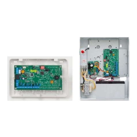
Pima VKD4net Operating manual

VKD4net Virtual Keypad Module
For controlling Intruder Alarm Systems over the Web
1. Introduction
VKD4net is a solution for creating a virtual keypad on a PC/laptop and connecting it over the
web to PIMA’s Hunter-Pro Series & Captain 8 Intruder Alarm Systems, for the purpose of
controlling the alarm system.
VKD4net can also be connected locally, over LAN.
Figure 1. The VKD4net operation diagram
The VKD4net hardware is made of the net4pro-i network module1and a BUS connection card.
The software part is PIMA’s VKD virtual keypad PC/laptop application, which connects to the
VKD4net over the internet. The VKD4net module is connected to the control panel’s BUS (on
the control panel or an expander).
Once connected, the virtual keypad function as a real LCD keypad, just as if was physically
connected to the control panel on the premises.
1.1. Out of the box
The VKD4net module installed in a plastic box
Installation CD including the product guide
CAT-5 cable, 2m
1.2. Preliminary requirements
The net4pro-i must be configured to carry a static IP address2;
PC/laptop with Windows XP©OS or newer;
4 wire harness.
1P/N 6247001
2See limited support notice in the end of this guide.
VKD4net
Virtual keypad
PC application
Internet

2
VKD4net Installation and Use Guide
2. Quick guide
Figure 2. VKD4net opened
Figure 3. VKD4net wiring diagram
3. Installation
It is recommended to install the VKD4net as close as possible to the BUS.
1. Connect the VKD4net to the BUS, using 4 wires. The connection can be directly to the
control panel’s KEYPAD terminals, or to a BUS terminal on an expander. Wiring is simple:
terminals “1” are connected between each other, terminals “2” are connected between
each other, and so on. Note that the overall BUS wires length is limited to 500m.
2. Connect the net4pro-i to the network using the supplied CAT 5 cable.
3. Install the VKD application; see “Installing & Running the VKD Application”, on page 6
for instructions.
4. Follow the next link to download and install the Lantronix Device Installer:
http://www.lantronix.com/device-networking/utilities-tools/device-installer.html
5. Run the device installer. If a windows security massage is displayed, Click “Unblock” or
“Allow Access”.
4. Configuration
4.1. Search for Xport©devices
1. In the Device Installer, click the Search icon (top-left). The application will now
search for Xport©devices on the network, i.e., the net4pro-i. If not found, check the
network connection and make sure the net4pro-i is connected to the same network as
the Device Installer’s PC/laptop.
In the next example, the Xport©device was identified in the IP address of
192.168.0.206.
Figure 4. Xport©devices found on the local network
4
1-V
2+V
3
VKD4net
1 2 3 4OUT
KEYPAD
IN+-
Control panel

VKD4net Installation and Use Guide
3
2. Click the plus sign on the left and click the device’s IP address, to display its details.
Figure 5. The device details screen
4.2. Web configuration
1. Click the Web configuration tab.
2. Click the green Navigate to button to the right of the address bar; see the next figure.
Figure 6. Web configuration screen
3. In the window that pops-up, Click OK. The Xport©Configuration Manager will now be
displayed.
Figure 7. XPort configuration screen
4.3. Network settings
1. Click Network on the left menu.
2. In the Use the following IP configuration section, enter the net4pro-i IP address,
the Subnet Mask and the Default Gateway (Router) address.
For example: IP address 192.168.0.206; Subnet Mask: 255.255.255.0; Default Gateway:
192.168.0.01.
3. Click OK to save. The word Done! should appear briefly next to the OK button.

4
VKD4net Installation and Use Guide
Figure 8. Network settings screen
4.4. Serial setting
1. Click Serial Setting on the left menu.
2. Set the Baud Rate to 2400.
3. Check the Enable Packing checkbox.
4. From the Idle Gap Time drop-down list, select 52 msec.
5. Click OK to save. The word Done! should appear next to the OK button.
Figure 9. Serial setting screen
6. Click Connection on the left menu; see the next figure.
7. From the Active Connect drop-down list, select None.

VKD4net Installation and Use Guide
5
4.5. Connection
1. In the Endpoint Configuration section, enter the Local Port number, i.e., the port
that the net4pro-i will listen to1. In the figure, the local port is set to 10001.
2. Click OK to save. The word Done! should appear next to the OK button.
Figure 10.Connection settings screen
3. Click Apply settings on the left menu. The net4pro-i will now reboot to apply changes.
Figure 11.Rebooting the net4pro-i
1. It is recommended to also reboot the net4pro-i manually, by disconnecting it
from power for a few seconds.
2. To connect the VKD4net over the Internet, you need to configure your Router for
“Port Forwarding”; see, for example the following link: http://portforward.com/
1Make sure the “Auto increment for active connection” checkbox is unchecked.

6
VKD4net Installation and Use Guide
5. Installing & Running the VKD
Application
The VKD Virtual Keypad application is supplied on a CD. To install it:
1. Insert the CD and wait for the installation wizard to run.
To manually run it, right-click the file VKD.exe, located
on the CD, and select Run as administrator.
2. From the drop-down list, select your language.
3. Click OK.
4. Click Next in the welcome screen.
5. Click “I accept the agreement” in the Software
License Agreement window and Next.
6. Click Next in the Select Destination Location
window, to install the VKD in its default location.
7. To install it on a different location, click Browse and
select a folder.
8. From the drop-down list, select Network Installation
in the Select Components window.
9. Click Next.
10.Click Next in the following two screens, then click Install.

VKD4net Installation and Use Guide
7
11.Uncheck Launch VKD in the wizard’s final screen.
12.Click Finish.
5.1. Setting the VKD’s IP and port
The net4pro-i’s IP address and port no. are taken from a text file, located in the 1VKD4net’s
folder:
1. Open a text editor (e.g., “Notepad”) and open the text file VKD_CUST.TXT.
2. The original file contains a sample module’s addresses: “192.168.0.1:10001;Sample”.
It is structured as follows: “IP:Port2;module’s name/description”. We advise you not to
delete this line, and keep it as a sample.
3. In the same structure enter the address of one or more net4pro-i. If you will use the
VKD4net for connecting to several customers, enter each address in a separate line.
4. Save the file and close it. If you have a security issue with saving the file in the default
folder, save it on your desktop and replace the original file with it afterwards.
5.2. Running the VKD for the first time
The first time you run the VKD, you need to select the module’s configuration from the
VKD_CUST.TXT text file. To do that:
1. Run the VKD by double clicking its shortcut on the desktop.
2. On the virtual keypad that appears, click the Settings icon; see the next figure.
Figure 12.The VKD virtual keypad3
3. From the Select Address drop-down menu, select your net4pro-i module. The
information here is taken from the text file.
4. Click OK and wait for the VKD to establish a connection.
1“C:/Program Files/Pima/VKD”by default.
2The port must be enabled by the network admin.
3If the text on the virtual keypad appears distorted

8
VKD4net Installation and Use Guide
Limited support notice:
Due to the diverse mix of networks, we are not able to offer support on routers, modems, switches or any other
network/ internet related devices or services.
Our support for internet or network related features, that are not directly related to the product are limited.
The following must be completed before calling our support team with network/internet related features:
Your network/internet must be configured and working.
IP address and port number for the product must be pre- configured on the network.
Also have the following information available: default Gateway, Subnet mask, port numbers and all other network
information.
PIMA Electronic Systems Ltd. shall have no liability for any death, personal and/or bodily injury and/or damage to
property or other loss whether direct, indirect, incidental, consequential or otherwise, based on a claim that the
Product failed to function.
Please refer to a separate warranty statement found on PIMA website at:
http://www.pima-alarms.com/site/Content/t1.asp?pid=472&sid=57
This document may not be duplicated, circulated, altered, modified, translated, reduced to any form or otherwise
changed; unless PIMA’s prior written consent is granted.
Please read this manual in its entirety before attempting to program or operate your system. Should you misunderstand
any part of this guide, please contact the supplier or installer of this system.
Copyright 2014 by PIMA Electronic Systems Ltd. All rights reserved.
PIMA Electronic Systems Ltd.
5 Hatzoref Street, Holon 58856, Israel
Tel: +972.3.6506414 Fax: +972.3.5500442
Email: support@pima-alarms.com
Web: http://www.pima-alarms.com
P/N 4410317
*4410317*
Version A2, XX en (Dec 2013)
Table of contents
Other Pima Control Unit manuals