ASG OM Series User manual

ASG, Division of Jergens, Inc.
15700 S. Waterloo Road | Cleveland, OH 44110-3898 | Phone: (888) 486-6163 | Fax: (216) 481-4519 | Email: [email protected] | Web: www.asg-jergens.com 1
Before Use
Please check for the following accessories before operating the machine:
Table of Contents
Overview .................................................................................................................1
Before Use ...............................................................................................................1
Operating Precautions .............................................................................................2
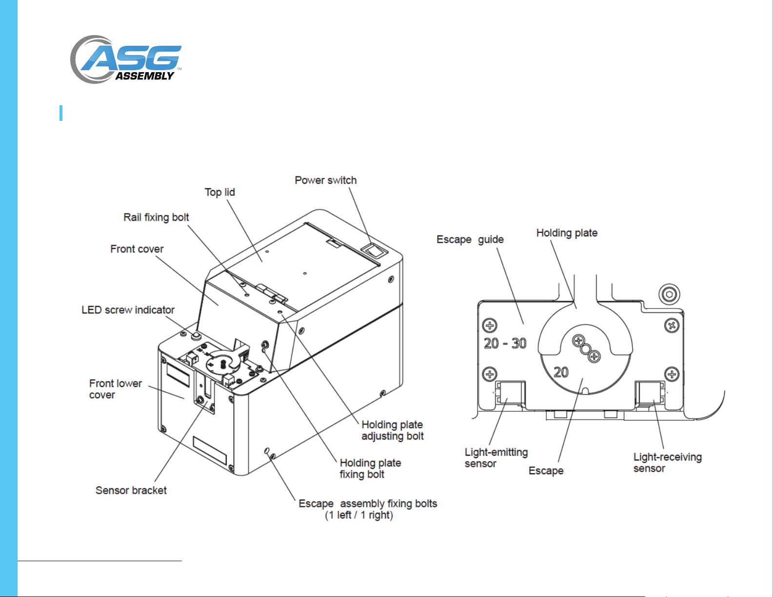
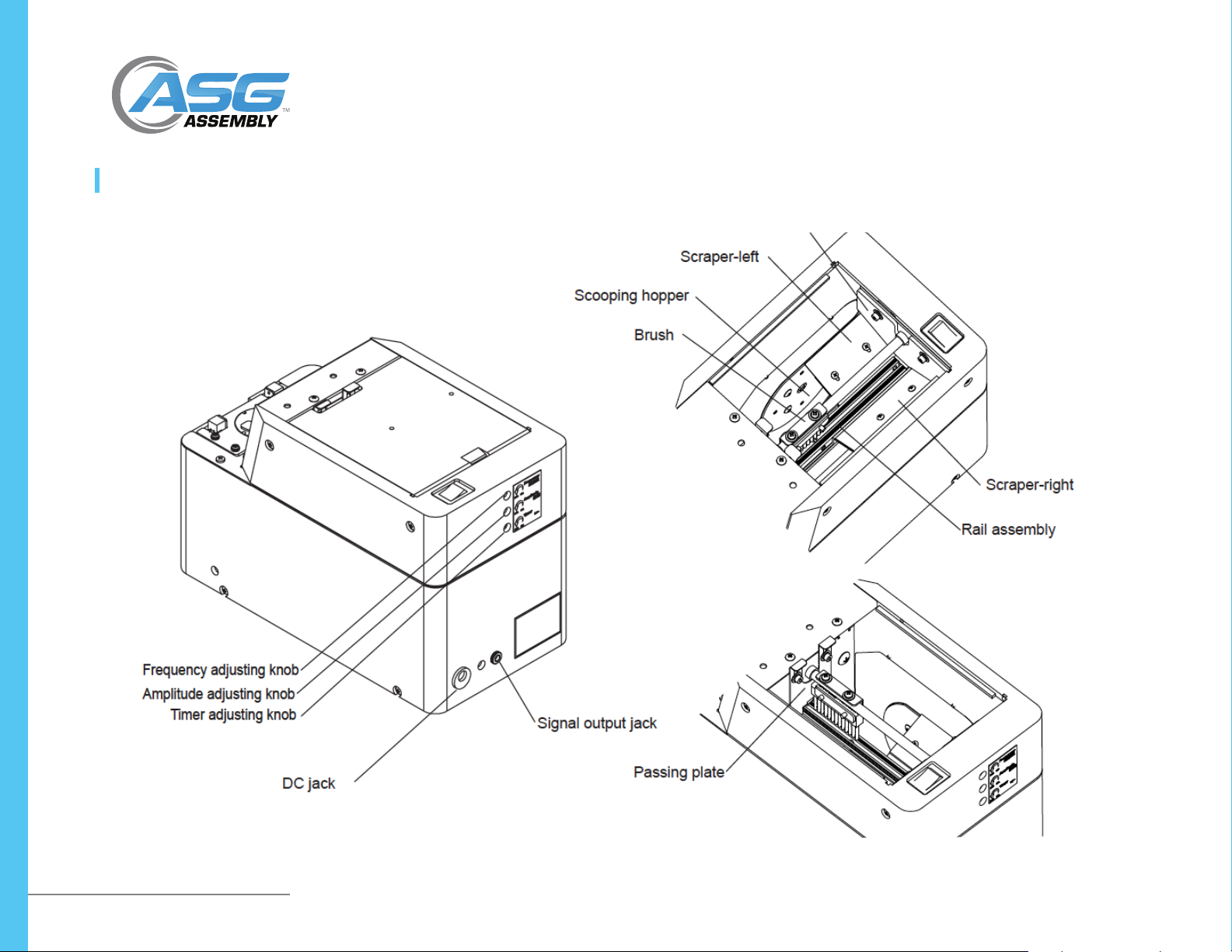
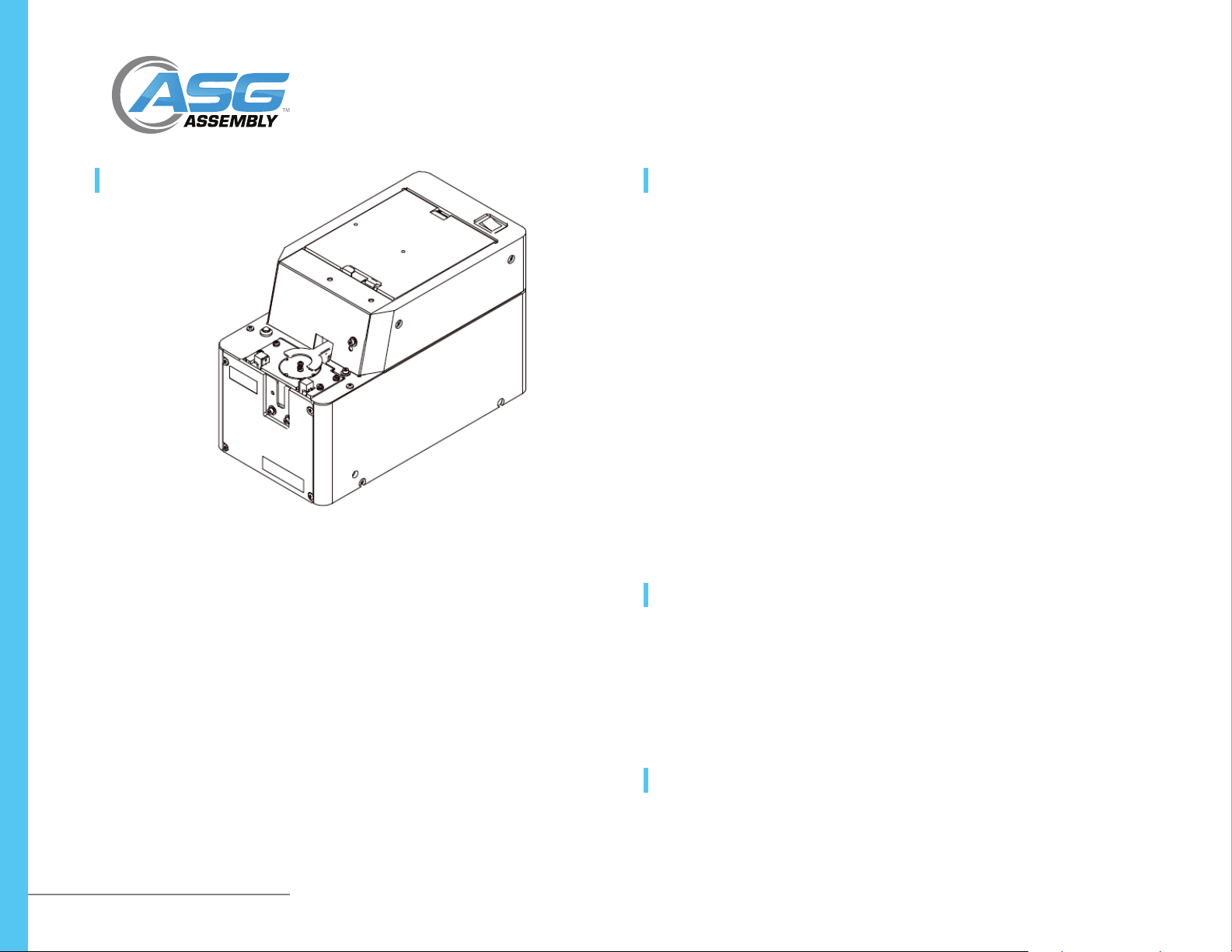
Names of Parts.........................................................................................................5
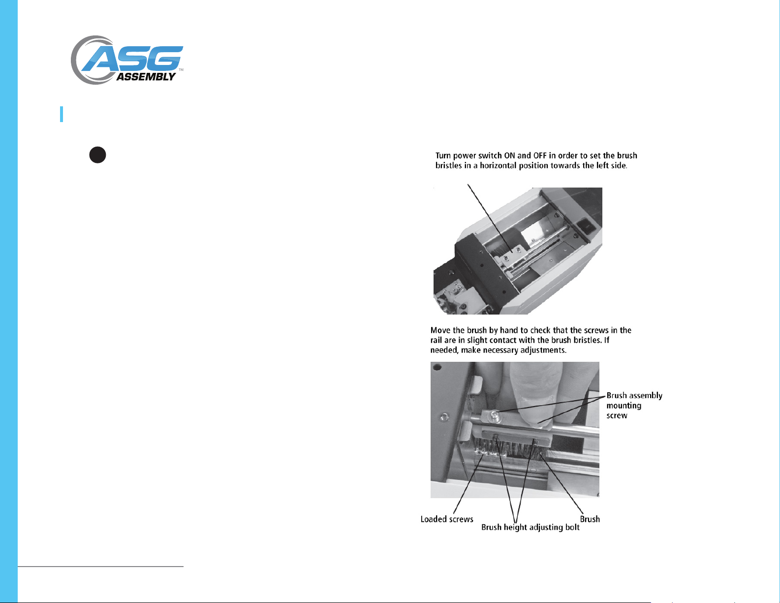
Adjustments and Checks Before Use........................................................................7
Maintenance..........................................................................................................15
Parts Adjustments and Replacements ....................................................................15
Application with Robotic System ...........................................................................25
Miscellaneous ........................................................................................................27
Troubleshooting .....................................................................................................29
Specications.........................................................................................................31
External Dimensions ..............................................................................................32
Warranty ................................................................................................................33
Overview
Thank you very much for selecting the OM Series Automatic Screw Feeder This machine
can line up screws (Type M2 - M6) and supplies them one by one to help the efciency
of screw fastening work. Different sizes of screws can be used by changing the rail and
parts of the escaper assembly. It can be used wherever there is a power source for an
AC adapter. Note: Only steel screws may be used with this machine. Stainless steel or
plastic screws cannot be used.
• (1) Instruction Manual
• (1) AC Adapter
• (1) Hexagonal Wrench
• (1) Screwdriver
• Read these instructions for the proper use of this machine.
• After having read these instructions, keep them in a convenient place so you or
the operator can refer to them whenever necessary.
OM-R Manual

ASG, Division of Jergens, Inc.
15700 S. Waterloo Road | Cleveland, OH 44110-3898 | Phone: (888) 486-6163 | Fax: (216) 481-4519 | Email: [email protected] | Web: www.asg-jergens.com 2
Operating Precautions
This manual contains safety alert symbols and signal words to help prevent injuries to
the user or damage to property.
This indicates there is a chance of death, serious injury, or re if the
instructions are not followed.
Symbols Indicating Type of Danger and Preventative Measures:
Prohibited operation. Never do this!
Do not disassemble, modify, or repair.
Do not touch with wet hands
This indicates to stop operations
Unplug power supply from wall outlet
General caution
Warning
Do not disassemble the AC adapter as there is a risk of electric shock, re, or
malfunction.
Do not damage, alter, or change the power cord. Do not place heavy objects
on the cord. Do not pull hard on the cord or twist the cord as it could be
damaged, thereby causing a risk of re or electric shock.
Do not handle the AC adapter with wet hands as it could cause an electric
shock.

ASG, Division of Jergens, Inc.
15700 S. Waterloo Road | Cleveland, OH 44110-3898 | Phone: (888) 486-6163 | Fax: (216) 481-4519 | Email: [email protected] | Web: www.asg-jergens.com 3
Operating Precautions (Continued)
When using an outlet with AC100 - 240V, don’t overload the electrical
circuit. Do not modify this machine as this may cause a re or electric shock.
Do not operate this machine near ammable liquids, gases, or materials as
there could be a risk of re or explosion.
Stop operating the machine and unplug the AC adapter from the wall outlet
when you detect overheating, smoke, a pungent odor, or any other unusual
condition, as there may be a risk of re or electric shock. Contact ASG for
additional information.
When performing maintenance, changing parts, or when you sense an
abnormality in the machine, turn the power off and unplug the AC adapter
from the wall outlet.
Use only the AC adapter supplied with this machine otherwise it may result
in a re or electric shock.
Do not install this machine in an unstable location otherwise it may fall
causing damage or injury.
Always operate the machine with the upper cover in place, otherwise it may
result in injury.
Do not allow any foreign material to enter the machine while in operation.
Do not put your ngers into the machine while in operation, otherwise an
injury may result.
Do not operate this machine in overly humid or dusty conditions. Keep the
socket plug clean at all times otherwise it may cause a re or electric shock.

ASG, Division of Jergens, Inc.
15700 S. Waterloo Road | Cleveland, OH 44110-3898 | Phone: (888) 486-6163 | Fax: (216) 481-4519 | Email: [email protected] | Web: www.asg-jergens.com 4
Operating Precautions (Continued)
When moving the machine, always disconnect the AC adapter from the wall
outlet or it may result in damage to the cord, or cause a re or electric shock.
Turn off the machine and unplug the AC adapter from the wall outlet when
not in use.
Do not operate the machine with tension on the AC adapter cord. Keep the
cord loose and untangled.
Do not bend, alter, or damage the rail. Do not apply any oil. It is
recommended that the user clean the rail periodically.
Do not use any screw that is out of the specied range nor any screw that is
oily or dirty.
Do not exert excessive force when picking up screws from the escape

ASG, Division of Jergens, Inc.
15700 S. Waterloo Road | Cleveland, OH 44110-3898 | Phone: (888) 486-6163 | Fax: (216) 481-4519 | Email: [email protected] | Web: www.asg-jergens.com 5
Names of Parts

ASG, Division of Jergens, Inc.
15700 S. Waterloo Road | Cleveland, OH 44110-3898 | Phone: (888) 486-6163 | Fax: (216) 481-4519 | Email: [email protected] | Web: www.asg-jergens.com 6
Names of Parts (Continued)

ASG, Division of Jergens, Inc.
15700 S. Waterloo Road | Cleveland, OH 44110-3898 | Phone: (888) 486-6163 | Fax: (216) 481-4519 | Email: [email protected] | Web: www.asg-jergens.com 7
Adjustments and Checks before Use
Check the Model Number
Ensure the model number of the screw presenter is appropriate for the size of screw
you are using.
Before delivery, each section of the machine is checked and adjusted with panhead
screws matching the nominal diameter of the model ordered. Operate the machine
with the screws loaded to check that the pick up is smooth. If the height or shape of
the screw head is different each section must be readjusted. If this is the case, make
the following checks and adjustments:
• Check the screw load amount
• Check and adjust the passing plate
• Check and adjust the holding plate
• Check and adjust the timer
• Check and adjust the brush
• Check and adjust the rail vibration
• Check and adjust the front and rear sides of the rail
If the rail, escape, robot escape guide and passing plate are replaced, screws with
a different nominal diameter can be accepted. After these parts are replaced, ne
adjusting is required.

ASG, Division of Jergens, Inc.
15700 S. Waterloo Road | Cleveland, OH 44110-3898 | Phone: (888) 486-6163 | Fax: (216) 481-4519 | Email: [email protected] | Web: www.asg-jergens.com 8
Adjustments and Checks before Use (Continued)
Basic Operations
Loading the Screws
• Turn the power switch ON and OFF so that the brush stops vertically above the
rail.
• Open the top cover and load screws on the left and right side of the rail evenly.
• Do not load screws above the surface of the rail.
CAUTION: Screws with a diameter larger than 5mm or longer than 20mm
under the head should not be loaded higher than the rail bottom.
• The type and length of screw changes the load capacity so check and adjust the
load accordingly.
• Do not overload the hopper with screws otherwise it may cause a malfunction or
damage the machine.
• This machine accepts only steel screws. Plastic or stainless screws are not
accepted.
Turning ON the Power
• Use only the adapter supplied with this machine to connect it to a wall outlet.
When you turn the power on, the switch lamp lights up, the motor rotates, and
screws are brushed onto the rail.
• The rail vibrates to deliver screws toward the end of the rail, then the escape
rotates to deliver screws to the pick-up location. When the screws come to the
stopper, the LED indicator lights up and the escape stops rotating.
• CAUTION: Use only the AC adapter supplied with this machine otherwise it may
cause damage to the machine.
!

ASG, Division of Jergens, Inc.
15700 S. Waterloo Road | Cleveland, OH 44110-3898 | Phone: (888) 486-6163 | Fax: (216) 481-4519 | Email: [email protected] | Web: www.asg-jergens.com 9
Adjustments and Checks before Use (Continued)
Picking Up Screws
• With screwdriver on the robot, pick up the screws at the stopper.
• Use the bit guide to guide the screwdriver bit vertically onto the screwhead.
• When inserting the screwdriver onto the screwhead, do not use excessive force as
it may alter the position of the escape or cause damage to the machine.
• Use the correct bit for the size of screw you are using.
Action of the Escape
• The escape rotates 90° clockwise, stops for 0.6 seconds, and rotates again 90°
clockwise. When a screw is caught in the escape and the notch position is altered,
the escape automatically rotates to the left to reestablish its position It will then
return to the correct rotation.
• This machine continues its operation when no screw is found at the screw pick up
location.
• The machine continues operating with a screw at the pick up location but will
stop after a certain period of time if the screw is not picked up.
• Once the screw is picked up, the machine starts operating again. This time period
can be varied by adjusting the timer.
• When no screw is found at the pick up location after a certain period of time, the
rail vibration increases. The vibration sound will also increase.
• If a screw is not found at the pick-up location, the machine stops operating. At
this time, the escape keeps rotating. Turn the power switch OFF and ON again
when you want to restart operation.

ASG, Division of Jergens, Inc.
15700 S. Waterloo Road | Cleveland, OH 44110-3898 | Phone: (888) 486-6163 | Fax: (216) 481-4519 | Email: [email protected] | Web: www.asg-jergens.com 10
Adjustments and Checks before Use (Continued)
Adjusting the Brush Height
Turn OFF the power switch before starting replacement and adjustment.
• Load the screws into the screw hopper and turn ON the power switch until the
screws are aligned in the rail.
• Turn power switch ON and OFF in order to set the brush to the left as shown in
the gure on the right.
• Move the brush by hand to check that the screws in the rail are in slight contact
with the brush bristles. If needed, make necessary adjustments.
• When the brush height is too high or low, this will have an adverse effect on the
screw alignment and transport.
• If any adjustment is necessary, loosen the brush height adjusting bolt to adjust
the brush height.
• If the plastic portion at the front of the brush comes into contact with the passing
plate, loosen the brush assembly mounting screw and move the brush assembly
back so there is no clearance.
• Turn ON the power switch to check that the brush operation is normal.
!

ASG, Division of Jergens, Inc.
15700 S. Waterloo Road | Cleveland, OH 44110-3898 | Phone: (888) 486-6163 | Fax: (216) 481-4519 | Email: [email protected] | Web: www.asg-jergens.com 11
Adjustments and Checks before Use (Continued)
Checking and Adjusting the Rail Vibration
• The amplitude and frequency of the rail vibration can be adjusted.
• The vibration has been adjusted at the factory for screws that correspond with the
rail.
• Put some screws into the rail and turn the power on. If they are delivered
smoothly, there is no need for adjustment.
• The screw transport feed differs depending on screw type.
• For screws with a low transport speed or screws that easily escape from the rail,
an adjustment is necessary.
1. Turn the frequency adjusting knob (rst hole at the top in the back of the
machine) using the accompanying screwdriver. Find the frequency at which the
rail vibrates appropriately.
2. Turn the amplitude adjusting knob (second hole from the top) and nd the
amplitude for which screws are delivered smoothly.
• If the vibration is adjusted too high, screws may escape from the rail and fall
into the machine. Adjust the vibration to a proper value that matches the loaded
screws.
• With the accompanying screwdriver, turn the knob without using excessive force.

ASG, Division of Jergens, Inc.
15700 S. Waterloo Road | Cleveland, OH 44110-3898 | Phone: (888) 486-6163 | Fax: (216) 481-4519 | Email: [email protected] | Web: www.asg-jergens.com 12
Adjustments and Checks before Use (Continued)
Check and Adjust the Front and Rear Sides of the Rail
Turn OFF the power switch before starting replacement and adjustment.
• If the rail comes into contact with the escape or the clearance between the rail
and escape is too large, loosen the rail screw. Hold the rail groove and adjust the
rail assembly either backward or forward. After making an adjustment, be sure to
tighten the rail screw.
• When the rail comes in contact with the escape, the escape disc doesn’t rotate
properly. When the clearance between the rail and the escape is too large, screws
may fall into the machine.
Check and Adjust the Rear Hopper Cover
Turn OFF the power switch before starting replacement and adjustment.
• Check that the clearance between the rear hopper cover and the rail assembly is
about 0.2 mm.
• If the rail hits against the rear hopper cover, the vibration will lessen and the
screws will be delivered slowly. If the rear hopper cover is too high, the chance of
screws falling between the rail and the scraper increases.
• If adjustment is required, loosen the rear hopper cover screws and make the
appropriate adjustments.
!
!

ASG, Division of Jergens, Inc.
15700 S. Waterloo Road | Cleveland, OH 44110-3898 | Phone: (888) 486-6163 | Fax: (216) 481-4519 | Email: [email protected] | Web: www.asg-jergens.com 13
Adjustments and Checks before Use (Continued)
Check and Adjust the Passing Plate
Turn OFF the power switch before starting replacement and adjustment.
• Check that the passing plate is adjusted to a height that permits loaded screws to
pass just within the limit.
• If the passing plate is too low, screws cannot pass. If the passing plate is too high,
the screws will not be transported smoothly.
• If adjustment is required, loosen the passing plate screw and adjust appropriately.
Check and Adjust the Holding Plate
• Check that the clearance between screws in the rail and the holding plate is
about 0-1mm.
• If any adjustment is required, loosen the holding plate attachment screw and turn
the holding plate adjusting screw to move the plate up or down.
• If there is no clearance, the screw cannot pass. If the clearance is too large, screw
may pile up or escape. Turn the holding plate adjusting screw clockwise to move
the plate down. Turn the holding plate adjusting screw counter-clockwise to move
the plate up.
!

ASG, Division of Jergens, Inc.
15700 S. Waterloo Road | Cleveland, OH 44110-3898 | Phone: (888) 486-6163 | Fax: (216) 481-4519 | Email: [email protected] | Web: www.asg-jergens.com 14
Adjustments and Checks before Use (Continued)
Check and Adjust the Timer
• The screw transport feed differs depending on screw type.
• Set the timer longer for screws with a low transport speed and shorter for screws
with a high transport speed.
• This machine continues its operation when no screw is found at the screw pick up
spot.
• The machine continues operating with a screw at the pick up location but will
stop after a certain time period if the screw is not picked up. This time period can
be varied by adjusting the timer. After the screw is picked up, the machine starts
operating again.
• Cover one of the optical sensors to make sure it’s working.
• Make an adjustment with the timer adjusting knob (the 3rd hole from the top) at
the rear of the machine body (as shown in the gure on the right).
• Turn the timer knob clockwise (as viewed from the rear side) to decrease the time
period. Turn the knob counter-clockwise to increase the time period.
Check and Adjust the Scraper
• Check that the clearance between the scraper right/left and the hopper wall right/
left, are around 0.4mm.
• When the scraper makes contact with the hopper wall, the rail vibration decreases
and the screws are delivered slowly. When the clearance between the scraper and
the hopper wall is too large, the screws may be caught by the scraper.
• If any adjustment is required, loosen the scraper attaching screw and move the
scraper plate up or down.
• If there is any damage to the plate, contact ASG.

ASG, Division of Jergens, Inc.
15700 S. Waterloo Road | Cleveland, OH 44110-3898 | Phone: (888) 486-6163 | Fax: (216) 481-4519 | Email: [email protected] | Web: www.asg-jergens.com 15
Maintenance
• A dirty rail may interfere with the screw transport speed. Clean the rail with a
soft, clean cloth dipped in alcohol. If cleaning is difcult, remove the rail from the
machine and clean the rail. Replace the rail if needed.
• Before removing the rail from the machine, be sure to turn off the power supply
and take the screws out of the hopper.
Part Adjustments and Replacement
• The brush and main motor are wearable parts.
• When using a different diameter of screw, the following items must be replaced:
rail, escape, and passing plate. These parts may be ordered separately. The
replacement and adjustment procedures are described on the next page.
• When replacing any parts, a ne adjustment is required. Make these ne
adjustments by following the instructions in this manual. Before replacing any
parts, be sure to remove all the screws from the hopper.

ASG, Division of Jergens, Inc.
15700 S. Waterloo Road | Cleveland, OH 44110-3898 | Phone: (888) 486-6163 | Fax: (216) 481-4519 | Email: [email protected] | Web: www.asg-jergens.com 16
Part Adjustments and Replacement
Replacing the Rail Assembly
Turn OFF the power switch before starting replacement and adjustment.
Before replacing, remove all the screws from the hopper, the rail, and the
escape.
The rail assembly of this machine can be easily replaced. If there is any dirt or aw on
the rail that prevents a smooth operation, we recommend cleaning or replacing the
rail. Use the passing plate, escape, and rail assembly that correspond to the diameter
of the screws to be used.
1. Remove the bottom front cover.
2. Loosen the escape assembly screws and pull out the escape assembly. Insert the
accompanying allen wrench into the left hole on the front top cover and loosen
the rail screw.
3. Pull out the rail assembly and replace it with a compatible rail.
Reassemble. After replacing the rail, adjustments are required. Fix the rail so that it
does not contact the escape and make sure that screws won’t fall into the clearance
between the escape and rail.
!

ASG, Division of Jergens, Inc.
15700 S. Waterloo Road | Cleveland, OH 44110-3898 | Phone: (888) 486-6163 | Fax: (216) 481-4519 | Email: [email protected] | Web: www.asg-jergens.com 17
Part Adjustments and Replacement (Continued)
Replacing and Adjustment of the Escape
Turn OFF the power switch before replacing.
Before replacing, remove all the screws from the hopper, the rail, and the
escape.
• When using screws with a different diameter, replace the escape, the robot escape
guide, the rail, and the passing plate.
• Raise the holding plate to replace and adjust the necessary parts. After
replacement, be sure to adjust and check the parts in the area of the escape.
When you remove the escape attaching screw, please use the driver specied for
M2 (bit No.0).
1. Remove the robot escape guide and the escape. Loosen and remove the attaching
screws of the robot escape guide and the escape.
2. Attach the robot escape guide and the escape that corresponds with the screw’s
nominal diameter. Assemble the escape loosely as it will need adjusting later.
Note that the stopper should not be on top of the escape. The stopper should be
laying at against the escaper guide-left. If it is not laying at, adjust.
!

ASG, Division of Jergens, Inc.
15700 S. Waterloo Road | Cleveland, OH 44110-3898 | Phone: (888) 486-6163 | Fax: (216) 481-4519 | Email: [email protected] | Web: www.asg-jergens.com 18
Part Adjustments and Replacement (Continued)
Replacing and Adjustment of the Escape (Continued)
3. Check the position of the parts for smooth delivery of the screws.
Check that the clearances between the outside edges of the rail and the
robot escape guide right and left are almost even. If they are in contact,
the screws cannot be delivered. If there is too much clearance on either
side screws may fall into the machine.
At this time, make the top surface of the escape even to or 0.1 - 0.5mm
lower than the rail surface. If it’s too high, the screw won’t enter an escape
notch. If it’s too low, a screw will not enter a notch properly.
If any adjustment is required, remove the cover, loosen the escape bracket
attaching screw and move it up or down, left or right and tighten the
screw.
!

ASG, Division of Jergens, Inc.
15700 S. Waterloo Road | Cleveland, OH 44110-3898 | Phone: (888) 486-6163 | Fax: (216) 481-4519 | Email: [email protected] | Web: www.asg-jergens.com 19
Part Adjustments and Replacement (Continued)
Replacing and Adjustment of the Escape (Continued)
4. Adjust the escape notch position.
• Turn the power switch ON while covering the sensor light axis with a small piece
of paper.
• When the power is ON, the screw sensor LED lights up and the escape rotates
around to the starting point.(Reference point run.)
• When the escape stops, loosen the attaching screws and adjust the escape
by hand so that an escape notch and the rail groove align. Tighten the escape
attaching screws.
• After adjustment, turn the power switch ON in order to make a reference point
run and check that an escape notch and the rail groove align.
• Next, remove the paper blocking the sensor’s optical axis and the escape will start
rotating.
• At each rotation stop, check that all 4 notches of the escape align with the rail.
• After checking and adjusting each component, do an operational check with
screws loaded.
• If any abnormality is found, make the said adjustments once again in addition to
the rail vibration and front/rear position adjustments.
• When installing the cover, take care not to catch or pinch the wires.

ASG, Division of Jergens, Inc.
15700 S. Waterloo Road | Cleveland, OH 44110-3898 | Phone: (888) 486-6163 | Fax: (216) 481-4519 | Email: [email protected] | Web: www.asg-jergens.com 20
Part Adjustments and Replacement (Continued)
Checking and Adjusting the Sensor
The following are rare situations that require adjustment:
• There is no screw at the pick up spot but, the LED is on and the escape doesn’t
rotate.
• There is a screw at the pick up location, but the LED is not on and the escape
rotates. Check the voltage when required.
• When checking the voltage, take the rear cover off and check the voltage level of
No. 7 pin of IC4050 and adjust the sensor bracket. When measuring the voltage
level, the metal part of the main body is the ground.
• When a screw is not at the pick up location, turn the power ON.
• Next loosen the 2 sensor bracket attaching bolts and do the following:
• Pull the sensor bracket down and check if the voltage is over 4V and if the
sensor light is ON. At this time, the escape is stopped.
• Next, while checking the voltage level, slowly push the sensor bracket
up which causes the voltage to decrease. When the voltage is around
0.25V-1.5V tighten the sensor bracket. During this procedure when the
voltage is around 2.5V, the LED screw sensor turns OFF and the escape
rotates.
• When there is no screw at the pick up location, the voltage is 0.25V-1.5V and the
LED screw indicator is OFF.
• When there is a screw at the pick up location and the voltage is over 3.5V, the
LED screw indicator is ON.
This manual suits for next models
1
Table of contents
Popular Industrial Equipment manuals by other brands

Siemens
Siemens LI-Z-BV Series installation instructions

Xylem
Xylem Bell & Gossett Ecocirc+ 20-18 Installation, operation and maintenance manual

MR
MR ComTroll 115C user manual

DRO PROS
DRO PROS EL400 quick start guide

Nitronic
Nitronic ST215W operating instructions

ABB
ABB UniSafe PowerIT Installation and maintenance instructions