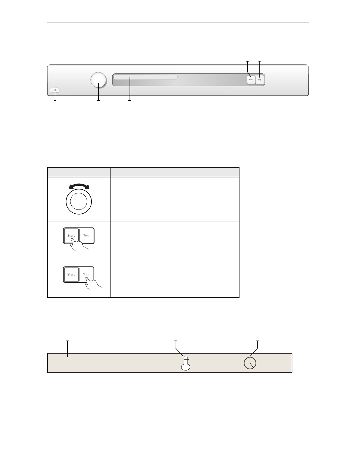
Component description
Components and measurement values
The specified resistance values apply at room temperature (about 20°C/68°F). Values within
±10% are considered normal.
Article no. Component Measurement value Comment
80 839 15 Motor 50 Hz,
220/240 V
Winding resistance:
cable colour red-white 26.5 Ω
cable colour red-blue 53.5 Ω
cable colour white-blue 27.0 Ω
Current: 0.7 A; 140 W; 2850 rpm
80 839 16 Motor 60 Hz,
220/240 V
Winding resistance:
cable colour red-white 26.5 Ω
cable colour red-blue 53.5 Ω
cable colour white-blue 27.0 Ω
Current: 0.7 A; 140 W; 3300 rpm
The motor is a 2-pin motor and is directly
connected to the fan for internal air and the
gearing for driving the cylinder. On condenser
dryers, the motor also drives the fan for external
air.
80 903 13 Capacitor 8 μF 50 Hz
80 903 14 Capacitor 6 μF 60 Hz
80 902 70 Capacitor heat pump 17 μF 50 Hz
80 902 71 Capacitor heat pump 60 Hz
80 821 28 Condensate pump 50 Hz
80 846 48 Condensate pump 60 Hz
80 762 02 EMC-filter with inductor The filter eliminates interference to and from the
machine.
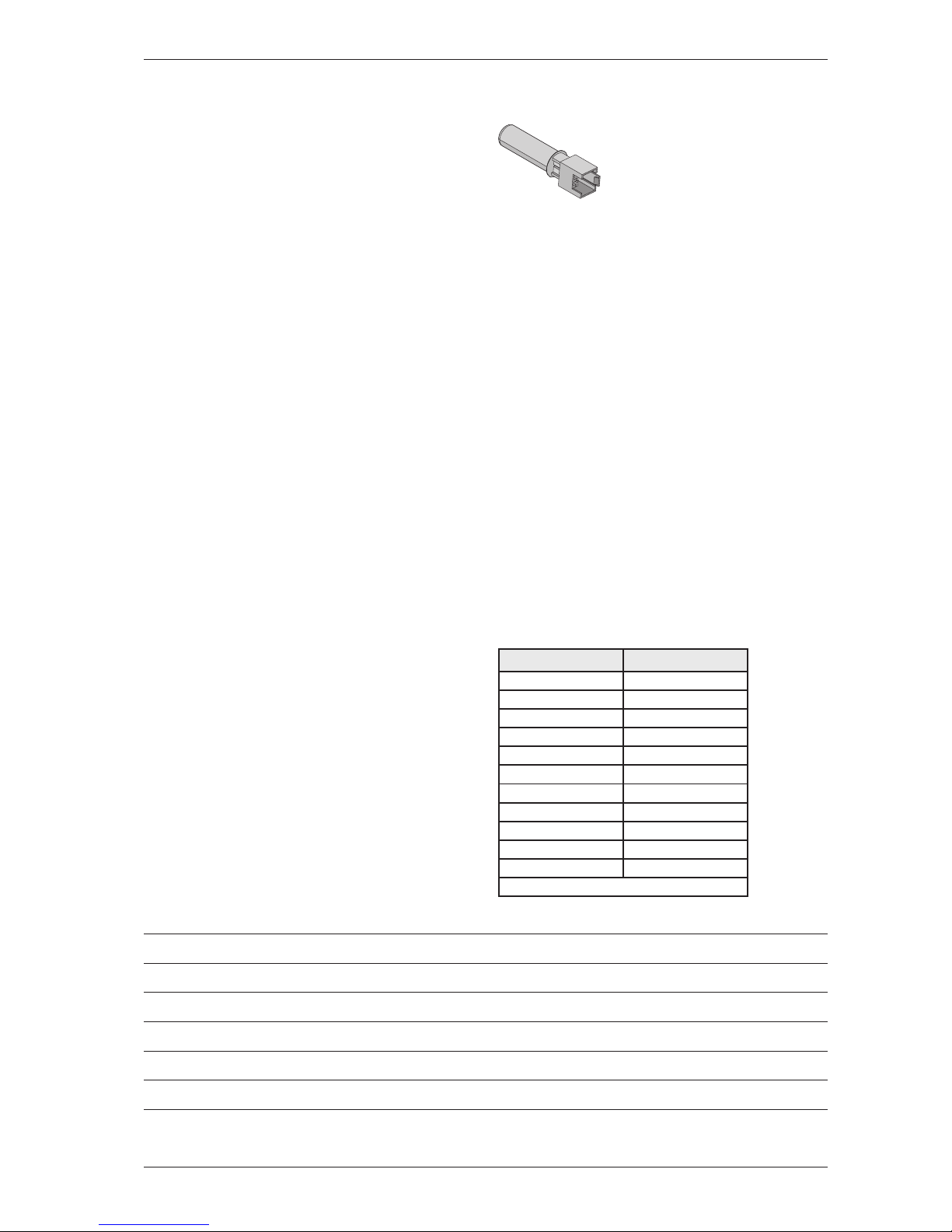
80 833 44 Thermistor 4.8 kΩ(at 25°C) The thermistor controls temperature regulation. If
the thermistor is short-circuited or detaches from
the control unit, the programme is stopped.
80 773 85 Thermostat 150 150°C automatic The thermostat/overheating cut-out stops the
programme if the temperature becomes too high.
80 792 00 Thermostat 135 135°C automatic
80 902 24 Thermostat 110 110°C automatic
80 761 04 Door switch The front door triggers a door switch which stops
the programme when the door is open. If the door
has been opened and closed during the programme
the machine must be restarted using the Start/Stop
button.
80 761 03 Microswitch float
Overflow guard
If both containers in the tumble dryer are full the
programme is stopped by a float switch installed
in the lower container. “Over flow” is indicated
on the display.
Electrical connection Condenser 1950W/10A-2500W/16A
Vented 1950W/10A-3000W/16A
Heat pump 1300W/10A
Heating Water Circuit 1950W/10A
The machine is delivered as single phase and can
be switched between 10 A and 16 A. The control
buttons are used to make the switch via the software.
Does not apply to Heat Pump or Heating Water
Circuit.
80 824 92 Heating element 1950 W Heater 1: 1950 W, 24.5 Ω
80 915 90 Heating element 2500 W Heater 1: 1950 W, 24.5 Ω
Heater 2: 550 W, 91.4 Ω
80 824 91 Heating element 3000 W Heater 1: 1950 W, 24.5 Ω
Heater 2: 1050 W, 45.5 Ω
80 824 60 Heating element 3000 W Heater 1: 1950 W, 90.2 Ω
Heater 2: 1050 W, 167.6 Ω
Marine 440 V
80 824 61 Heating element 3000 W Heater 1: 1950 W, 24,5 Ω
Heater 2: 1050 W, 45,5 Ω
3-Phase
80 916 18 Heating element 2500 W Heater 1: 1950 W, 24,5 Ω
Heater 2: 550 W, 91,4 Ω
3-Phase
80 821 30 Cooling fan compressor heat
pump
637 Ω
80 821 22 Base heat pump complete 50 Hz
80 821 23 Base heat pump complete 60 Hz
80 88 415 Reversing valve 1.9 kΩ
80 841 00 Steam generator 68 Ω
Thermistor 61.4 kΩ
Steam pump 2.15 MΩ
Supplied with steam pump
80 902 22 Reed switch steam tank
80 889 37 Control unit compl. TD70.C The control unit contains microprocessors for
controlling programmes, the motor, the heating
elements etc.
80 846 49 LED-light compl. LED-technology for the machine’s internal light.
Service Manual TD70.C
9