Aspect BIS VISTA Operating and installation instructions

BIS VISTAMonitoring
System
SERVICE INFORMATION MANUAL
Aspect Medical Systems, Inc.
Bispectral Index(BIS) Monitoring System
Rx only
EC REP
Aspect Medical Systems, Inc. Aspect Medical Systems International B.V.
One Upland Road 3454 PV De Meern
Norwood, MA 02062 USA Rijnzathe 7d2 0123
(Tel) 617-559-7000 The Netherlands
(Tel) 888-BIS INDE(X) (U.S. only) Tel: +31.30.662.9140
(Fax) 617-559-7400 Fax: +31.30.662.9150
www.aspectmedical.com
075-0015 1.00


BIS VISTAMonitoring
System
SERVICE INFORMATION MANUAL
Aspect Medical Systems, Inc.
Bispectral Index(BIS) Monitoring System
Copyright, 2006, Aspect Medical Systems. All rights reserved. Copying or other
reproduction of this document is prohibited without prior written consent of Aspect
Medical Systems.
BIS VISTA, BISx and the BISx logo are trademarks of Aspect Medical Systems, Inc.
Aspect, Bispectral Index, BIS, the BIS logo, and Zipprep are trademarks of Aspect Medical
Systems, Inc. and are registered in the USA., EU and other countries.


v
TABLE OF CONTENTS
ABOUT THIS MANUAL............................................................................................................. VIII
1SAFETY PRECAUTIONS.................................................................................................... 1-1
1.1 WARNINGS ................................................................................................................................................. 1-1
1.2 CAUTIONS................................................................................................................................................... 1-4
1.3 KEY TO SYMBOLS........................................................................................................................................ 1-6
2BIS VISTA MONITORING SYSTEM OVERVIEW ........................................................... 2-1
2.1 INTRODUCING THE BIS VISTA MONITORING SYSTEM .......................................................................... 2-1
2.2 PRINCIPAL COMPONENTS.......................................................................................................................... 2-2
2.2.1 The BIS VISTA Monitor........................................................................................................................................ 2-2
2.2.2 The BISx and Patient Interface Cable (PIC) ................................................................................................... 2-4
2.3 INSTRUMENT IDENTIFICATION .................................................................................................................. 2-4
2.4 PROPRIETARY INFORMATION AND DEVICES ............................................................................................ 2-5
3PRINCIPLES OF OPERATION .......................................................................................... 3-1
3.1 HOW THE BIS VISTA MONITORING SYSTEM WORKS ........................................................................... 3-1
3.2 SYSTEM ARCHITECTURE ............................................................................................................................. 3-1
3.2.1 The BISx................................................................................................................................................................... 3-3
3.2.2 The BIS VISTA Monitor........................................................................................................................................ 3-5
3.3 SYSTEM FEATURES ....................................................................................................................................... 3-6
3.3.1 System Self Checks ............................................................................................................................................... 3-6
3.3.2 Diagnostic Codes ................................................................................................................................................... 3-7
3.3.3 Monitor Data Memory......................................................................................................................................... 3-7
3.3.4 BISx Data Memory ............................................................................................................................................... 3-8
3.3.5 Saved Settings......................................................................................................................................................... 3-8
3.3.6 Battery Operation.................................................................................................................................................. 3-8
3.3.7 Data Transfer and Software Updates ............................................................................................................. 3-9
4PREPARATION FOR USE AND INSTALLATION ......................................................... 4-1
4.1 ENVIRONMENT............................................................................................................................................ 4-1
4.1.1 Shipping and Storage Environment .................................................................................................................. 4-1
4.1.2 Operating Environment........................................................................................................................................ 4-1
4.1.3 Power Requirements and System Grounding................................................................................................. 4-2
4.1.4 Site Preparation: Mounting the Monitor ......................................................................................................... 4-2
4.2 INSTRUMENT CONNECTIONS.................................................................................................................... 4-4
4.2.1 Connecting the BISx.............................................................................................................................................. 4-4
4.2.2 Power Cord Connections...................................................................................................................................... 4-4
4.3 INSTALLATION AND VERIFICATION PROCEDURE .................................................................................... 4-4
5CARE AND CLEANING...................................................................................................... 5-1
5.1 CARE AND CLEANING................................................................................................................................5-1
5.1.1 Cleaning the Monitor and BISx.......................................................................................................................... 5-1
5.1.2 Disinfecting the Monitor and BISx.................................................................................................................... 5-1
5.1.3 Cleaning the Monitor Display............................................................................................................................. 5-2
6PREVENTIVE MAINTENANCE ......................................................................................... 6-1
6.1 PHYSICAL INTEGRITY INSPECTION ............................................................................................................ 6-1
6.2 SYSTEM CHECKOUT ................................................................................................................................... 6-1
6.2.1 Monitor Checkout Procedure.............................................................................................................................. 6-2

vi
6.2.2 BISx Checkout Procedure .................................................................................................................................... 6-3
6.2.3 Patient Interface Cable (PIC) Checkout Procedure....................................................................................... 6-4
6.3 CHECKING THE BATTERY .......................................................................................................................... 6-5
6.4 CHECKING LEAKAGE CURRENT ................................................................................................................ 6-6
7DIAGNOSTICS AND TROUBLESHOOTING ................................................................. 7-1
7.1 GENERAL TROUBLESHOOTING ................................................................................................................. 7-1
7.2 BIS VISTA MONITORING SYSTEM TROUBLESHOOTING PROCEDURE................................................... 7-2
7.3 BIS VISTA SYSTEM MESSAGES AND CORRECTIVE ACTIONS .................................................................. 7-4
8SERVICING THE BIS VISTA SYSTEM.............................................................................. 8-1
8.1 REPLACING THE PIC................................................................................................................................... 8-1
8.2 REPLACING THE BISX................................................................................................................................. 8-1
8.3 REPLACING THE MONITOR........................................................................................................................ 8-2
8.4 REPLACING THE BATTERY.......................................................................................................................... 8-3
8.5 REPLACING THE POWER SUPPLY ............................................................................................................... 8-4
8.6 REPLACING THE CLAMP SHOE................................................................................................................... 8-5
8.7 REPLACING THE MONITOR INTERFACE CABLE ........................................................................................ 8-6
8.7.1 Parts and Tools Required .................................................................................................................................... 8-6
8.7.2 Procedure:................................................................................................................................................................ 8-6
8.8 REPLACING THE BISX BULKHEAD CONNECTOR..................................................................................... 8-9
8.8.1 Parts and Tools Required .................................................................................................................................... 8-9
8.8.2 Procedure:..............................................................................................................................................................8-10
8.9 CALIBRATING THE TOUCH SCREEN........................................................................................................ 8-13
8.10 USING THE RESET BUTTON ..................................................................................................................... 8-13
8.11 BISX CHECKOUT AND SAFETY TESTS..................................................................................................... 8-13
8.12 WHAT TO DO WITH A COMPONENT THAT REQUIRES SERVICE .......................................................... 8-14
8.13 REPACKAGING FOR SHIPPING AND STORAGE........................................................................................ 8-14
9SPECIFICATIONS AND WARRANTY............................................................................. 9-1
9.1 GENERAL SPECIFICATIONS ......................................................................................................................... 9-1
9.2 ELECTROMAGNETIC COMPATIBILITY SPECIFICATIONS ............................................................................ 9-5
9.2.1 Accessories............................................................................................................................................................... 9-5
9.2.2 IEC 60601-1-2:2001 Electromagnetic Compatibility Guidance............................................................... 9-6
9.3 WARRANTY .............................................................................................................................................. 9-11
10 APPENDIX I........................................................................................................................ 10-1
10.1 ACCESSORIES AND SPARE PARTS LIST..................................................................................................... 10-1
10.2 SENSOR SIMULATOR: P/N: 186-0137 ........................................................................................... 10-2
10.3 TEST SENSOR............................................................................................................................................. 10-3
10.4 SAFETY TESTER CONNECTION WITH PIC.............................................................................................. 10-5
11 APPENDIX II ...................................................................................................................... 11-7
11.1 DATA FLOW DIAGRAM............................................................................................................................ 11-7
11.2 BLOCK DIAGRAM ..................................................................................................................................... 11-8

vii
TABLE OF FIGURES
Figure 1 - Symbol Key (page 1 of 3)................................................................................ 1-6
Figure 2- The BIS VISTA Monitoring System.................................................................. 2-2
Figure 3 - Rear Panel ...................................................................................................... 2-3
Figure 4 - The BISx and PIC ........................................................................................... 2-4
Figure 5 - The BIS VISTA System Block Diagram .......................................................... 3-2
Figure 6 - The BIS VISTA Data Flow Diagram .............................................................. 3-3
Figure 7 - Pole Clamp ..................................................................................................... 4-3
Figure 8 - Schematic of Sensor Simulator Circuit........................................................ 10-2
Figure 9 - Sensor Simulator.......................................................................................... 10-3
Figure 10 - BIS Sensor................................................................................................... 10-3
Figure 11 - Connecting electrodes #2 and #4. .............................................................. 10-4
Figure 12 - Connecting electrode #3 with #4, and #1 with #2. .................................... 10-4
Figure 13 - Safety Tester Contact Points....................................................................... 10-5

ABOUT THIS MANUAL
_______________________________________________________________________
viii
ABOUT THIS MANUAL
This manual contains information necessary for the customer to install, maintain, service,
identify and prepare for use Aspect Medical Systems’ BIS VISTAMonitoring System. Also
included are directions to diagnose, troubleshoot, and repair the system. A spare parts and
accessories list and system specifications are included.
This manual is intended to be used in combination with the BIS VISTA Monitoring System
Operating Manual.
The BIS VISTA Monitoring System is designed and manufactured using state-of-the-art
components and manufacturing processes. Field repair or customer repairs are therefore
limited by design to replacement of major component assemblies such as the Patient
Interface Cable (PIC), BISx™, or the power supply and battery of the BIS VISTA monitor.
This manual, in conjunction with the BIS VISTA Monitoring System Operating Manual,
contains the maintenance and diagnostic troubleshooting information necessary for
customer qualified technical personnel to test and replace those parts of the equipment that
are replaceable by the customer. Aspect does not authorize nor provide information to
service or repair the internal components of the BIS VISTA monitor, with the exception of
the power supply and battery.
Before attempting to set up or service the BIS VISTA Monitoring System, please familiarize
yourself with the safety information provided in Section 1 of this manual.

SECTION 1 SAFETY PRECAUTIONS
________________________________________________________________________
1-1
SECTION 1
1SAFETY PRECAUTIONS
INTRODUCTION:
Caution:
Carefully read the BIS VISTA Monitoring System Operating Manual
entirely before using the monitor in a clinical setting.
WARNINGS, CAUTIONS, AND NOTES
The terms warning, caution, and note have specific meanings in this manual.
•A WARNING advises against certain actions or situations that could result in
personal injury or death.
•A CAUTION advises against actions or situations that could damage equipment,
produce inaccurate data, or invalidate a procedure, although personal injury is
unlikely.
•A NOTE provides useful information regarding a function or procedure.
KEY TO SYMBOLS
A key to the symbols used on the BIS VISTA Monitoring System appears at the end of this
section.
1.1 Warnings
THE USE OF ACCESSORY EQUIPMENT NOT COMPLYING WITH THE
EQUIVALENT SAFETY REQUIREMENTS OF THIS EQUIPMENT MAY
LEAD TO A REDUCED LEVEL OF SAFETY OF THE RESULTING SYSTEM.
CONSIDERATION RELATING TO THE CHOICE SHALL INCLUDE:
•USE OF THE ACCESSORY IN THE PATIENT VICINITY
•EVIDENCE THAT THE SAFETY CERTIFICATION OF THE
ACCESSORY HAS BEEN PERFORMED IN ACCORDANCE TO THE
APPROPRIATE IEC 60601-1 AND/OR IEC 60601-2-26 HARMONIZED
NATIONAL STANDARD.
WHEN CONNECTING EXTERNAL EQUIPMENT (e.g., DATA CAPTURE
COMPUTER), THE SYSTEM LEAKAGE CURRENT MUST BE CHECKED
AND MUST BE LESS THAN THE IEC 60601-1 LIMIT.
EXPLOSION HAZARD: DO NOT USE THE BIS VISTA SYSTEM IN A
FLAMMABLE ATMOSPHERE OR WHERE CONCENTRATIONS OF
FLAMMABLE ANESTHETICS MAY OCCUR.
MONITOR IS NOT DESIGNED FOR USE IN MRI ENVIRONMENT.

SECTION 1 SAFETY PRECAUTIONS
________________________________________________________________________
1-2
FOR PROPER GROUNDING, THE POWER RECEPTACLE MUST BE A
THREE-WIRE GROUNDED OUTLET. A HOSPITAL GRADE OUTLET IS
REQUIRED. NEVER ADAPT THE THREE-PRONG PLUG FROM THE
MONITOR TO FIT A TWO-SLOT OUTLET. IF THE OUTLET HAS ONLY
TWO SLOTS, MAKE SURE THAT IT IS REPLACED WITH A THREE-SLOT
GROUNDED OUTLET BEFORE ATTEMPTING TO OPERATE THE
MONITOR.
IF THE INTEGRITY OF THE EXTERNAL PROTECTIVE EARTH GROUND
IS IN DOUBT, THE BIS VISTA SYSTEM SHALL BE OPERATED FROM ITS
INTERNAL BATTERY POWER SOURCE ONLY.
FOR BIS VISTA SYSTEMS USED OUTSIDE OF NORTH AMERICA: A
HARMONIZED LINE CORD WITH CONDUCTORS HAVING A CROSS
SECTIONAL AREA GREATER THAN 0.75 mm2MUST BE USED.
BE SURE THE MONITOR IS MOUNTED SECURELY IN PLACE TO AVOID
PERSONAL OR PATIENT INJURY.
UNIVERSAL PRECAUTIONS SHALL BE OBSERVED TO PREVENT
CONTACT WITH BLOOD OR OTHER POTENTIALLY INFECTIOUS
MATERIALS. PLACE CONTAMINATED MATERIALS IN REGULATED
WASTE CONTAINER.
WHENEVER AN EVENT SUCH AS SPILLAGE OF BLOOD OR SOLUTIONS
OCCURS, RE-TEST BEFORE FURTHER USE.
DO NOT MIX DISINFECTING SOLUTIONS (e.g., BLEACH AND AMMONIA),
AS HAZARDOUS GASES MAY RESULT.
ELECTRICAL SHOCK HAZARD: THE MANUFACTURER'S INSPECTION OF
THIS APPARATUS VERIFIED THAT THE GROUND LEAKAGE CURRENT
AND THE PATIENT SAFETY CURRENT WERE LESS THAN THE
SPECIFIED LIMITS ESTABLISHED BY THE APPLICABLE SAFETY
STANDARDS. AS A MATTER OF SAFE PRACTICE, THE INSTITUTION
SHOULD CONDUCT PERIODIC TESTS TO VERIFY THESE CURRENTS.
ELECTRICAL SHOCK HAZARD: DO NOT REMOVE MONITOR COVERS
DURING OPERATION OR WHILE POWER IS CONNECTED TO MONITOR.
GROUND WIRE LEAKAGE CURRENT MUST BE CHECKED WHENEVER
INSTRUMENT CASE IS OPENED BY A QUALIFIED BIOMEDICAL
ENGINEERING TECHNICIAN.
POWER SUPPLY IS INTERNALLY FUSED. REPLACE POWER SUPPLY ONLY
WITH ASPECT MEDICAL SYSTEMS BIS VISTA POWER SUPPLY.

SECTION 1 SAFETY PRECAUTIONS
________________________________________________________________________
1-3
ENSURE THAT THE BISx DOES NOT COME INTO PROLONGED
CONTACT WITH PATIENT’S SKIN, AS IT MAY GENERATE HEAT AND
CAUSE DISCOMFORT.
THE CONDUCTIVE PARTS OF ELECTRODES OR SENSOR AND
CONNECTORS, INCLUDING THE NEUTRAL ELECTRODE, SHOULD NOT
CONTACT OTHER CONDUCTIVE PARTS, INCLUDING EARTH.
TO REDUCE THE HAZARD OF BURNS IN THE HIGH-FREQUENCY
SURGICAL NEUTRAL ELECTRODE CONNECTION, THE SENSOR OR
ELECTRODES SHOULD NOT BE LOCATED BETWEEN THE SURGICAL
SITE AND THE ELECTRO-SURGICAL UNIT RETURN ELECTRODE.
THE SENSOR MUST NOT BE LOCATED BETWEEN DEFIBRILLATOR
PADS WHEN A DEFIBRILLATOR IS USED ON A PATIENT CONNECTED
TO THE BIS VISTA SYSTEM.
TO MINIMIZE THE RISK OF PATIENT STRANGULATION, THE PATIENT
INTERFACE CABLE (PIC) MUST BE CAREFULLY PLACED AND SECURED.
SHOCK HAZARD: DO NOT ATTEMPT TO DISCONNECT THE POWER
CORD WITH WET HANDS. MAKE CERTAIN THAT YOUR HANDS ARE
CLEAN AND DRY BEFORE TOUCHING THE POWER CORD.
CONSIDERATIONS WHEN USING ELECTRO CONVULSIVE THERAPY
(ECT) EQUIPMENT DURING BISMONITORING:
SEPARATE ECT ELECTRODES FROM THE BIS SENSOR AS MUCH AS
POSSIBLE TO MINIMIZE THE EFFECT OF INTERFERENCE.
CERTAIN ECT EQUIPMENT MAY INTERFERE WITH THE PROPER
FUNCTION OF THE BIS MONITORING SYSTEM. CHECK FOR
COMPATIBILITY OF EQUIPMENT DURING PATIENT SETUP.

SECTION 1 SAFETY PRECAUTIONS
________________________________________________________________________
1-4
1.2 Cautions
Read this entire manual carefully before using the monitor in a clinical setting.
To turn off all A/C power, disconnect power cord from A/C outlet. Battery can be
removed to shut down unit completely.
Continuous impedance checking may need to be disabled if the 1 nanoampere 128
Hz impedance check signal interferes with other equipment (e.g., evoked potential
monitors).
Do not autoclave the BISx or Monitor. Autoclaving will seriously damage both
components.
Avoid liquid ingress to the Patient Interface Cable. Contact of fluids with the PIC
sensor connector can interfere with PIC performance.
Check the battery periodically by operating a BIS VISTA monitor that has been
disconnected from the wall socket and that has been charged to full capacity (at least
6 hours of charge time). After long periods of storage (e.g., more than 1 month) it
may be necessary to cycle (charge, then discharge) the battery a few times to get full
charge capacity. If the BIS VISTA monitor fails to operate reliably from the battery
for approximately 45 minutes, battery replacement is required.
The BIS VISTA monitor contains an internal lithium ion battery. The battery must
be removed by a qualified service technician and disposed of or recycled in
accordance with the national laws of the country. Contact Aspect Medical Systems,
Inc. or the local distributor for a replacement battery: Aspect part number 186-0208.
All repairs to the BIS VISTA Monitoring System should be made only by a qualified
Biomedical Engineering Technician or other authorized personnel.
Use only the parts and tools specified. Use of any others may damage the
instrument.
Using accessories other than those specified may result in increased electromagnetic
emissions or decreased electromagnetic immunity of the BIS VISTA Monitoring
System.
The BIS VISTA Monitor should not be used adjacent to or stacked with other
equipment. If adjacent or stacked use is necessary, the BIS VISTA monitor should
be observed to verify normal operation in the configuration in which it will be used.
Do not block ventilation inlet holes on the underside of monitor.

SECTION 1 SAFETY PRECAUTIONS
________________________________________________________________________
1-5
Do not open the BISx for any reason. The seal to prevent liquids from entering the
BISx may be damaged if opened. Service or repairs must be performed only by
qualified biomedical technicians.
The BIS VISTA system has been designed to operate with a BIS Sensor. The sensor
is a silver/silver chloride electrode array that utilizes Aspect's patented Zipprep
technology and uses a proprietary connector. Use of other electrodes is not
recommended.
Do not disconnect the BISx during the software upgrade.
The BIS VISTA system complies with the electromagnetic compatibility
requirements of EN60601-1-2. Operation of this device may affect or be affected by
other equipment in the vicinity due to electromagnetic interference (EMI). If this
occurs:
•Increase separation between devices
•Re-orient device cabling
•Plug devices into separate outlet circuit branches
Refer to Section 9.2 “Electromagnetic Compatibility Specifications.”
When connecting or disconnecting BISx, take care not to touch the exposed contacts
of either connector. Damage due to electrostatic discharge may result.
All work involving opening the instrument case must be performed in a static-safe
environment to prevent damage to electronic components and assemblies. This
environment includes the operator, work area and tools, and any other test or storage
items that might touch the monitor or BISx assemblies.
Important:
The BIS VISTA systems comply with the European Medical Device Directive
(MDD) and applicable regulatory requirements of the country distributed to and
carry the CEXXXX Marking. Declarations of Conformity provided upon request
where appropriate.
SECTION 1 SAFETY PRECAUTIONS
________________________________________________________________________
1-6
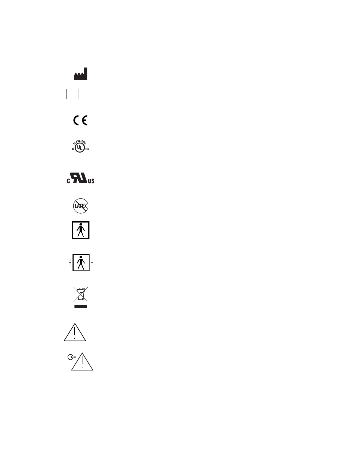
1.3 Key to Symbols
Manufacturer
EC REP
Authorized Representative in the European Community
Conformité Européenne (CE) Marking of Conformity to European
Medical Device Directive. CEXXXX represents the Notified Body
number
Classified by Underwriters Laboratories Inc.with respect to electric
shock, fire and mechanical hazards only, in accordance with
UL 60601-1 and IEC60601-2-26
Recognized under the Component Recognition Program of
Underwriters Laboratories Inc.
Latex-free product
Type BF Equipment
Type BF Equipment Defibrillator-proof
Crossed out wheelie bin indicates separate treatment from general
waste at end of life
Attention, Consult Accompanying Documents
Attention, Data I/O, RS-232 Serial Port, Consult Accompanying
Documents
Figure 1 - Symbol Key (page 1 of 3)
SECTION 1 SAFETY PRECAUTIONS
________________________________________________________________________
1-7
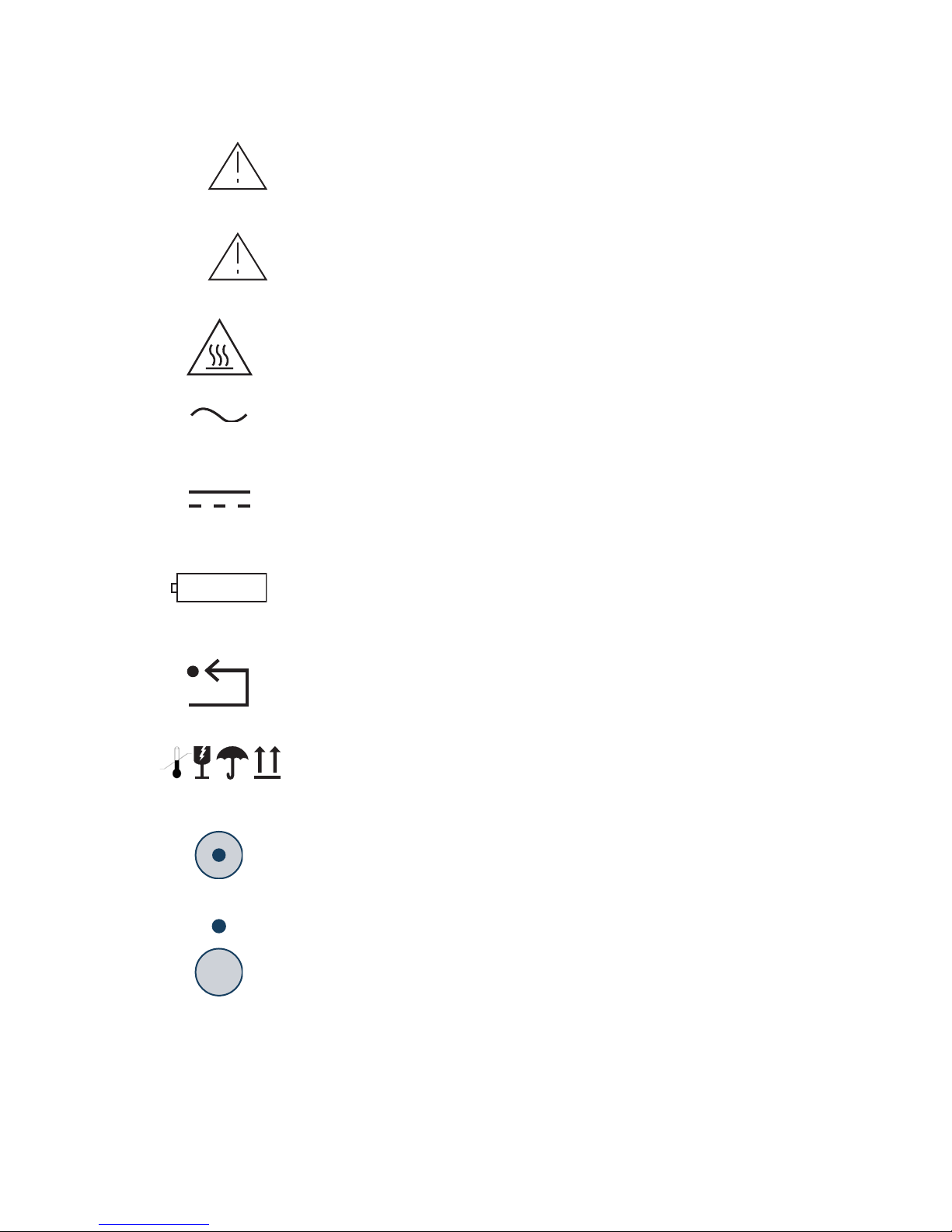
USB-A
Attention, USB-A, Host. Consult Accompanying Documents
USB-B
Attention, USB-B function. Consult Accompanying Documents
Caution: Hot Surface
Alternating Current
D/C Current
Battery Location
Reset Button
Packaging Labelling:
Storage Temperature Limits, Fragile, Do Not Get Wet, and This
Side Up
Monitor Power ON
Monitor Power OFF or Standby Mode
Figure 1 - Symbol Key (page 2 of 3)

SECTION 1 SAFETY PRECAUTIONS
________________________________________________________________________
1-8
Operating on Battery
No Battery is Installed in Monitor
Ringing Bell Icon - Alarm Sounding
Green Bell Icon - Alarms Active
Yellow Bell with Dotted Line ‘X’ - Alarms Paused
Red Bell with ‘X’ - Alarms Silenced
A green box denotes ON or active condition.
A red box with an ‘X’ denotes OFF or cancel.
Figure 1 - Symbol Key (page 3 of 3)

SECTION 2 BIS VISTA MONITORING SYSTEM OVERVIEW
_______________________________________________________________________
2-1
SECTION 2
2BIS VISTA MONITORING SYSTEM
OVERVIEW
2.1 Introducing the BIS VISTA Monitoring
System
The BIS VISTA Monitoring System is intended for use under the direct supervision of a
licensed healthcare practitioner or by personnel trained in its proper use. The BIS VISTA
Monitor is intended for use on adult and pediatric patients within a hospital or medical
facility providing patient care to monitor the state of the brain by data acquisition of EEG
signals.
The BIS may be used as an aid in monitoring the effects of certain anesthetic agents. Use of
BIS monitoring to help guide anesthetic administration may be associated with the reduction
of the incidence of awareness with recall in adults during general anesthesia and sedation.
The BIS VISTA Monitoring System processes raw EEG signals to produce a single number,
called the Bispectral Index, or BIS, which correlates to the patient’s level of hypnosis. It
operates from an AC power source of 100V to 240V, 50/60Hz, and provides approximately
45 minutes of automatic back-up battery power.
The monitor is menu-driven with on-screen touch keys. A detailed description of how the
BIS VISTA Monitoring System works is included in the BIS VISTA Operating Manual.
Please refer to the BIS VISTA Operating Manual for additional information.
SECTION 2 BIS VISTA MONITORING SYSTEM OVERVIEW
_______________________________________________________________________
2-2
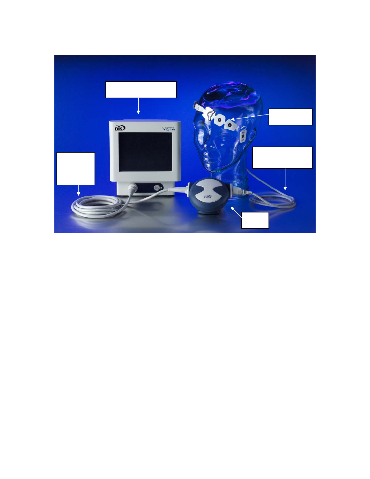
Figure 2- The BIS VISTA Monitoring System
2.2 Principal Components
The system is composed of a monitor, a BISx, a Patient Interface Cable (PIC), and BIS
sensor.
2.2.1 The BIS VISTA Monitor
The front panel of the BIS VISTA monitor contains the Touch Screen, BISx port and the
ON/Standby button. See Figure 2.
Touch Screen
The BIS VISTA monitor is designed so that all controls (with the exception of the
ON/Standby button) are accessible by touching a designated area on the monitor screen.
This area is called a touch key. The touch keys are designed to function even when the user
is wearing examination gloves.
Monitor
Interface
Cable
BIS VISTA monitor
BISx
Patient Interface
Cable (PIC)
BIS sensor
SECTION 2 BIS VISTA MONITORING SYSTEM OVERVIEW
_______________________________________________________________________
2-3
ON/Standby button
The ON/Standby button is located in the lower right corner of the monitor and is used to
put the monitor in ON or in Standby mode. When the small LED light to the right of the
ON/Standby button is green, the unit is running and providing power to the BISx. When it
is yellow, the battery is charging and the system is in Standby mode. When it is not lit, no
A/C power is available to the unit; pressing the ON/Standby button will start up the
monitor using the battery.
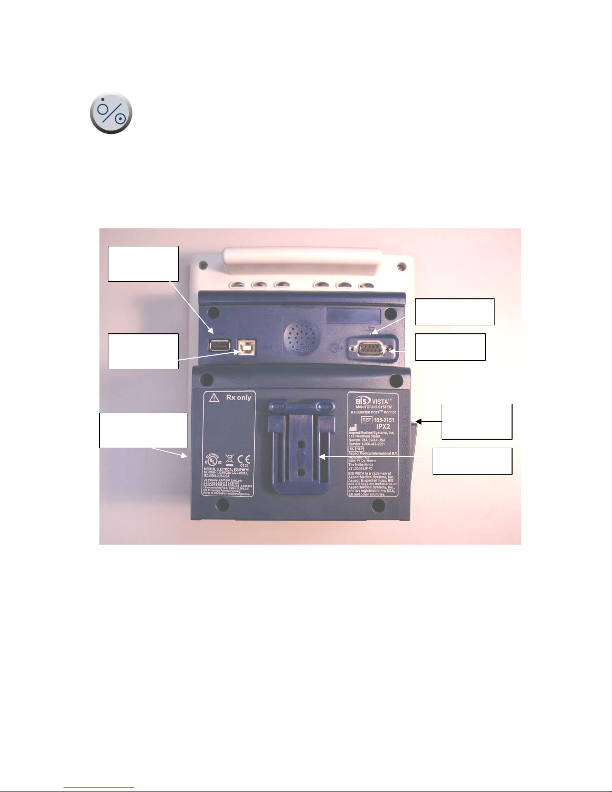
Clamp Shoe
Serial Port
USB Port
(Type A)
USB Port
(Type B)
Reset Button
Battery/Power
Supply Cover
Power Cord
Receptacle
Figure 3 - Rear Panel
Rear Panel
The rear panel components are pictured in Figure 3. They include: two USB ports (Type A
and B), the clamp shoe, an RS-232 port, the Reset button, the Battery/Power Supply cover,
and the power cord receptacle.
The clamp shoe allows the monitor to slide into the pole clamp so that it can be attached to
a ½" – 1 ½" diameter vertical pole.
SECTION 2 BIS VISTA MONITORING SYSTEM OVERVIEW
_______________________________________________________________________
2-4
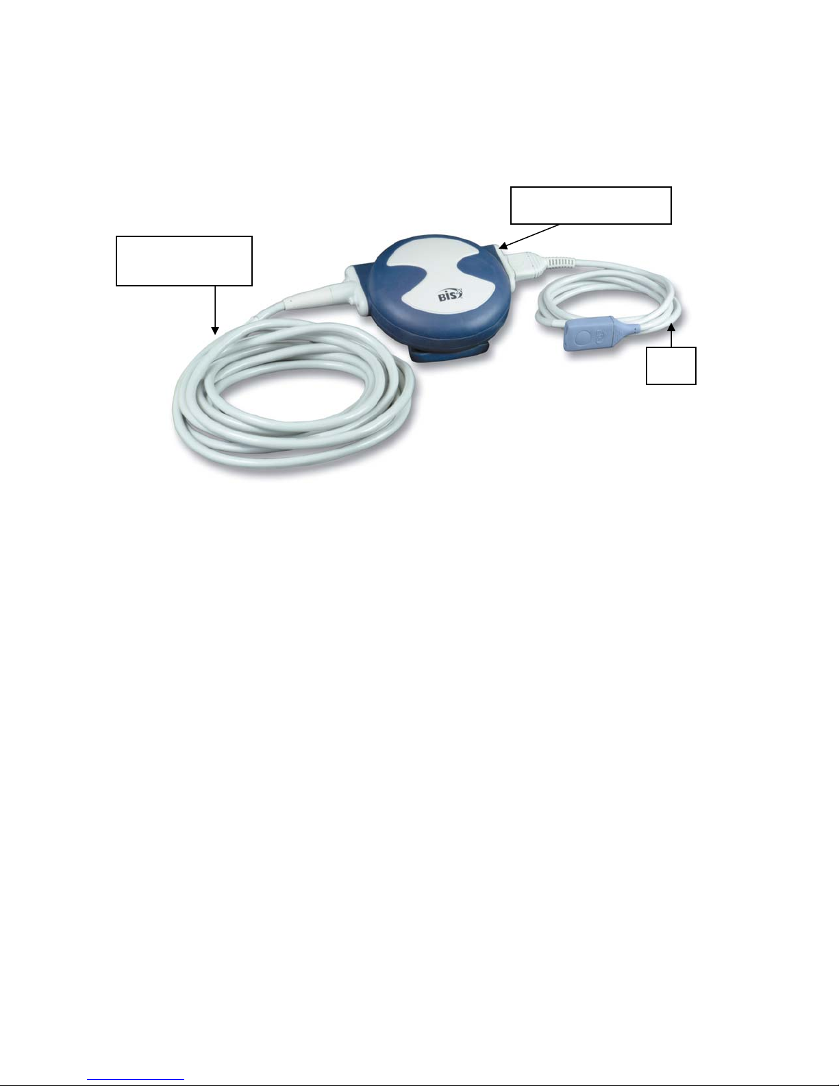
2.2.2 The BISx and Patient Interface Cable (PIC)
The BISx receives, filters, and processes patient EEG signals. It is located close to the
patient's head where the EEG signal is less subject to interference from other medical
equipment.
Figure 4 - The BISx and PIC
The BISx is shown in Figure 4. Its long flexible Monitor Interface Cable connects to the
front of the monitor. The Patient Interface Cable (PIC) connects the BIS sensor to the
BISx.
The attachment clip on the BISx is used to secure it in a convenient location near the
patient's head.
2.3 Instrument Identification
BIS VISTA Monitor
Monitor identification information is permanently marked on the rear panel. This
information includes instrument model and serial numbers, power ratings, cautions, and the
Aspect Medical Systems shipping address.
BISx
The BISx identification information is permanently marked on its rear panel. This
information includes instrument model and serial numbers and cautions.
The PIC
The Patient Interface Cable lot number is stamped on the cable itself.
Software Revision Numbers
Software revision numbers may be displayed by pressing the “Configuration Information”
touch key in the menu system.
Bulkhead Connector
Monitor Interface
Cable
PIC
Table of contents


