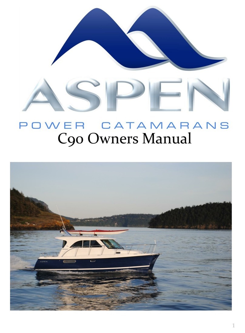
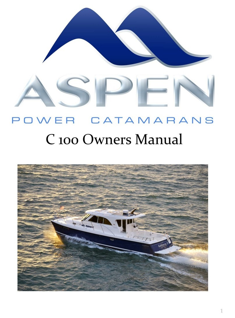
Aspen C108 User manual

C108 OWNERS MANUAL

2
SECTION TOPIC PAGE
SECTION 1 Specifications 4 –6
Service Points 7
SECTION 2 Aspen Warranty 8
Boat US Membership 9
SECTION 3 Getting Started 10 -12
Batteries & Chargers 13 –16
AC / DC Panels 17 -19
Tank Gauges 20
Fuse Panels 21 -23
Pump Locations 24
SECTION 4 Equipment & Systems 25 -28
Air Conditioning Unit 29
Anchor Operation 30 -31
Tilt Helm & Curtains 32 -33
Fuel System 34
Raw Water Ball Valves 35
Motor Pod Drain Valves 36
Fresh Water System 37 -38
LPG System 39 -41
Teak Care 42
Zinc Replacement Thruster 43
Trailering 44 -45
Lifting Strap 46 -47
Dinghy Launch 48
Outfitting Your Boat 50 -58
Open Hull Photos 59 -61
SECTION 5 Troubleshooting 62 -66
Thruster Maintenance 67 -74
Winterizing 75
SECTION 6 Larry’s Notes: Thruster Logic & Strategy 76
Larry’s Notes: Toilet Logic, Details, Magic 77 -81
Anchoring Woes 82 -86
Service Schedules 87 -89

VESSEL SPECIFICATIONS
VESSEL NAME:
HULL IDENTIFICATION NUMBER:
MANUFACTURER:
Aspen
MODEL:
C108
LENGTH OVERALL:
37’-8”
LENGTH AT WATER LINE:
35’
BEAM:
10’8”
DRAFT:
31” | 22” Trimmed
DISPLACEMENT:
9,700lbs
HULL MATERIAL:
Fiberglass
BOTTOM PAINT:
SeaHawk Biocop
3
ENGINE
Yamaha F200XB
–Yamaha F115
DINGHY
ELECTRONICS
GARMIN AIS800
GARMIN Reactor 40 CCU
GARMIN GMR18XHD RADAR
GARMIN GHC20
GARMIN GPS MAP 8610
GARMIN 8612xsv

CAPACITY SPECIFICATIONS
4
Unit Capacity Material
Holding Tank
30 Gallons Polypropylene
Starboard Water Tank
24 Gallons Polypropylene
Port Water Tank
26 Gallons Polypropylene
Port Fuel Tank #1
43 Gallons Aluminum
Port Fuel Tank #2
44 Gallons Aluminum
STBD Fuel Tank #3
97 Gallons Aluminum
Engine Oil
–200hp 4.76 Quarts Yamaha Lube
4M FC W
Engine Oil
–115hp 3.9 Quarts Yamaha Lube
4M FC-W
Hot Water Tank
6 Gallons
Batteries House Bank
Amp Hours

ENGINE SPECIFICATIONS
(Reference only –check your engine owners manual)
ENGINE MANUFACTURER: YAMAHA 200 & 115
MODEL NUMBER:
F200
MODEL NUMBER:
F115
SERIAL NUMBER:
SERIAL NUMBER:
FUEL TYPE:
Gas
FUEL TYPE
: Gas
ALTERNATOR AMPERAGE:
50
ALTERNATOR AMPERAGE:
35
PROPELLER DIAMETER: 14.5”
PROPELLER DIAMETER:
13.125”
PROPELLER PITCH: 13” SS
PROPELLER PITCH: 16” SS
NUMBER OF BLADES: 3
PROPELLER MATERIAL: Stainless Steel
PRIMARY FUEL FILTER:
6P3-WS24A-
01
-00
PRIMARY FUEL FILTER
: 6D8-WS24A-00
-
00
INLINE FUEL FILTER:
69J-24501-10
INLINE FUEL FILTER
: 68V-24502-30-00
ENGINE OIL TYPE: YAMAHA LUBE
OIL FILTER:
69J-13440-03-00
OIL FILTER
: 5GH-13440-70-00
ENGINE OIL QUANTITY: 4.76 qt
ENGINE OIL QUANTITY: 3.9 qt
SPARK PLUGS:
LFR5A-11
SPARK PLUGS
: LFR6A-11
5

SERVICE POINTS & PARTS
(Reference only –check your engine owners manual)
1
OIL CHANGE
Yamaha Lube (115hp)
4M FC-W 3.9 qts
Yamaha Lube (200hp)
4M FC-W 4.76 qts
Oil Filter (115hp)
5GH-13440-70-00 1
Oil Filter (200hp)
69J-13440-03-00 1
2
GEAR OIL CHANGE
115hp
Yamaha Marine Gearcase Lube
SAE 90 API GL-4 .70 qt
200hp
Yamaha Marine Gearcase Lube
SAE 90 API GL-4 1.036 qt
3
ZINCS
Trim Tab Zinc (115hp)
6EF-45371-01-00 1
Engine Zinc (115hp)
67F-11325-01-00 1
Trim Tab Zinc (200hp)
61A-45371-00-00 1
Engine Zinc (200hp)
6G5-45251-02-00 1
6

7

8

GETTING STARTED
ANCHORING
The anchor is on the bow roller. Note: if the winch runs but the line/chain is not coming in,
the clutch is most likely not snugged up. Using the wrench (Lewmar) from the blue owner’s
info bag, insert it in the top of the winch and tighten clockwise. Test again, be careful not to
tighten too far as the bow roller can be bent with the motor’s force.
BATTERIES
One house and the start battery are located in the starboard aft cockpit lazarette
compartment. The main house battery is located starboard mid ship under the ¼ berth.
BILGE PUMPS
There are 3 bilge pumps per hull –each in watertight compartments. All bilge pumps are on
automatic float switches and powered by full time power, even if the switches at the dash
are off. (Power comes from hot float breaker)
DINGHY
Always wear your life jacket when using the dinghy. The dinghy typically has a 450lb capacity
and allows 3- 4 people on board safely.
FUEL TANKS (Standard)
2 tanks holding 30 gallons each (port side), and a 3rd tank holding 70 gallons (starboard
side). Expedition tanks hold 180 gallons, 103 starboard, and (2) 38-gallon tanks to port.
HOLDING TANK
The holding tank holds 30 gallons. To empty, be 3 miles offshore (if legal in your state) and
hold macerator switch on to dump. It’s best to do when the engine is off so you can hear the
change in motor speed when the tank is dry. There is also a pump outfitting on the step
through at the transom gate.
HEATER
Wallace 30D runs off auxiliary (3 gallon/kerosene) fuel tank located in port hull (Forward
lazarette locker). Or optional Propex propane heater behind the refrigerator running off the
propane tank in the port aft cockpit storage locker.
HOT WATER
There is a 6-gallon hot water tank –110V located in the starboard lazarette.
SAFETY EQUIPMENT (Option)
Aspen boats are typically equipped with 8 life jackets: two under the helm seat (suspender
inflating type), 4 in the starboard aft cockpit storage compartment, and two under the
master bed. The flare kit and first aid kit are also stored under the helm seat. Fire
extinguishers are located to port side of helm and on the aft wall of the ¼ berth.
9

SHORE POWER
Boat comes equipped with a 30-amp service cord. Note: It’s best not to exceed a 25-amp draw or
plug damage may occur. Be sure to twist lock to cord in place for complete connection at the
pedestal.
STOVE:
The stove is propane and has a 15lb propane tank. Remember to turn the tank on at the bottle,
and then push the toggle switch next to the sniffer control to feed it power. Then turn on the
sniffer control unit to the right of the stove. Turn switch at stove off after use and close bottle if
leaving the boat for an extended period. Note: When starting the burner, you must hold the
control knob in for 10 seconds after it’s lit to heat the blowout safety sensor while pushing the
ignition button.
WATER
The boat has 2 water tanks, one in each hull. To activate the port tank, switch the water pump
switch at the dash to port side. To activate the starboard tank, move switch to starboard. If switch
is centered, both pumps are off. Capacity is 50 gallons. Remember to not run water continuously
to conserve your water supply.
QUICK START
The main battery switches are typically left on, the AC and DC breakers at the helm are switched
on or off as needed.
A. ENGINE CHECKS: engine oil level should be checked monthly or at the start of
each major trip. Before starting, prime both engines’ fuel systems by gently squeezing
the fuel primer bulb located port and starboard lazarette aft. Squeeze bulb until fuel priming
bulb becomes firm. This greatly reduces cranking time after the engine has set unused for
more than 2 days.
B. COVERS & CUSHIONS: aft deck cooler should be pulled out of the ¼ berth and
placed on the non-skid mat.
C. READY INSTRUMENTS: no action needed.
D. POWER PANELS: DC switches are normally off when leaving the boat for an
extended period of time. This kills power to 95% of the DC equipment. Note: if you
want the refrigerator left on, the lower sub-panel switch must be on. AC panel
breakers are also typically all on except the hot water 110V heater breaker –use
this only when needed as, with other loads, you can exceed 30 amps.
E. START ENGINE: assure throttles are in neutral position. Slip the safety lanyards
in. Turn the key until engine starts.
F. CASTING OFF: remove lines in appropriate manner and stow safely. Then remove
fenders/lines and stow safely. Never leave lines on cleats while underway.
G. UNDERWAY: attentive helmsman at all times.
H. ARRIVING AT MARINA: place fenders on proper side. Remember that neutral is
your friend. Use thrusters once, near dock. 5 second bursts–not more than 30 total.
I. ANCHORING: remove snubber line (safety line/bungee on anchor). Check to
see line in locker is clear and not bound by stored gear. Either at the helm or on the
deck, lower the anchor using switch pad. While retrieving, be sure to clean anchor
(bounce while in water) to clear mud and debris before it gets on the deck and in
the anchor locker.
General Note: If you activate the depth sounder/chartplotters while on land you must deactivate
the depth sounder module, or the transducer will overload and be damaged.
GETTING STARTED
CONTINUED
10

BOTTOM PAINT
We use SeaHawk Biocop paint (PN 1205-1), typically black. This paint is good for boats stored in
and out of the water. We also protect the transducer and metal parts optionally with non copper
biocide antifouling Pettit paint (PN: MDR-720).
PAINTING PROCEDURE
The typical yard will make a major mess of bottom painting an Aspen, as they do not care about
how smooth the final finish is. Their goal is gobs of paint fast, no finesse, paint spurs are OK.
Our goal is a smooth finish that keeps the boat speed at 100% of new. We mix the paint
extremely well, then strain it so it flows well when you apply it with a marine FOAM roller (you’ll
need 9” roller on large surfaces and 4” to move fast in detail areas). We quickly roll the paint in
an area about 3 feet long by 3 feet high, and then put the roller down and go over this area with
a quality 4” finish paint brush lightly TIPPING the surface. When you do it right, the paint lays
down very flat –no lines are present, and no paint spurs are sticking up –smooth as Formica.
The key to this is tipping while the paint is still wet, roll the next section forward 3 feet and tip it
while the first is still WET so you don’t get scuff lines in the paint at the transition points. Try to
end your painted sections on a chine or other hull feature for a smooth finish everywhere. You
might be asking, why do it this way? Aspens are a displacement hull, so when it’s running all –
100% of the hull stays in the water. If you turn this surface into 36 grit sandpaper, it drastically
slows down the boat. We had one owner whose yard did a very lumpy paint job and he lost
5mph off his cruise and top speed. The whole paint job had to be sanded off.
We do two coats on all surfaces, a third on the sides and sun exposed areas, and a fourth on the
bow. On re-coat jobs, it typically takes a day to prep the surface and a day to do the coating.
Note: The paint is ablative which means the glue that holds it together slowly dissolves over time.
Due to this every 4-5 years, you will need to strip all the paint off and start at fresh fiberglass.
You’ll know its time when it starts to flake off after a season of use. Note 2: Bottom paint is a
wear item like car tires, it typically lasts 12-18 months before recoating is needed. Note 3:
When/If you decide to have a diver clean the bottom it’s best to scrub with a piece of Berber
carpet or equivalent, never use a coarse Scotch-Brite or pad unless you plan to repair soon.
PRODUCTS NEVER TO USE ON YOUR BOAT
Swimming pool cleaner (Muriatic Acid)
Soft Scrub with bleach
Comet
Scotch Bright Sponges
Toluene
Acetone
Anything really strong will take the expensive UV stabilizers out of the gel coat surface. And with
no UV protection, the boat will chalk and age.
GETTING STARTED
CONTINUED
11

12
BATTERY SWITCHES
The C108 has five main battery switches:
1
EMERGENCY PARALLEL
Starboard cockpit
2
ENGINE ON/OFF
Starboard cockpit
3
HOUSE ON/OFF
Starboard ¼ berth
4
BOW THRUSTER
Starboard ¼ berth
5
STERN THRUSTER
Starboard ¼ berth
6
INVERTER (under bed)
Starboard ¼ berth
Normal operation position is to leave both
House, Electronics, and Engine switches in
the ON position. Emergency Parallel should
be in the OFF position and is rarely used and
then only for 3 to 5 minutes max.
Thruster battery switches are located as noted
above and are normally ON. These must be
switched OFF when swimmers are in the
water, or for service. The thrusters are very
powerful and will suck objects in the water
toward them. Do not operate the thruster for
more than 30 seconds in one docking or the
motor’s thermal breaker may shut the motor
off until it cools down.
The batteries have three charging sources:
1. 1 MasterVolt charger (25-amp output for
the Start Battery & 25A for the House
Battery). Works when shore power is
connected and AC breakers at dash are
switched on.
2. 2 130 watt solar chargers (12A) while
anchored –automatic.
3. 1 50-amp & 25-amp engine-driven
alternators.
The boat has a Blue Sea Voltage Sensitive Relay
(black box located near the switches) that
disconnects the House Batteries from the Start
Battery when the voltage on the Start Battery drops
below 12.3 volts. Once the charging system has
brought the Start Battery back to 12.3 volts, it
reconnects to the House Battery Bank for charging
while underway.

BATTERY LOCATIONS
13
ENGINE START BATTERY
LEAD ACID G27
Note: on Generator boats we double up the start batteries and locate in
aft starboard hull for weight and balance issues.
HOUSE BATTERIES (Standard)
Golf Cart 6Volt Deep cycle, AGM lead acid, in
series for 12V house supply.
(under bed cushion)
Start
G27
Aft house
G27

14
The first cushion in the starboard stateroom is removable. Under is a removable
access plate. This space has 2 golf cart house battery's (AGM) style, the optional
2000-watt charger (100 amp-12v/2000-watt 110V) inverter as well as a Master
Volt duel out put 20-amp charger for the house and start battery bank. It also
includes a raw water pump to supply the heads flush water.
HOUSE BATTERY
Inverter Room
Battery /Inverter room
ventilation. Outlet. Inlet
behind head bowel.

INVERTERS & CHARGERS
(Magnum & MasterVolt)
The 25 Amp 3 channel House MasterVolt automatic charger is wired to come on when the
boat’s shore power is connected and the A/C breakers at the dash are in the ON position.
The chargers are four-stage, smart units that charge aggressively when the battery is low
and then ramp down as it charges. They stop completely when the battery is fully charged
and do a small topping charge weekly. The design greatly extends battery life and prevents
overcharging and subsequent battery damage. Note 1: You must use AGM batteries as they
do not out gas Note 2: chargers will only charge if they see voltage. If batteries are dead, you
will need to use the Emergency Parallel Switch and charge for a maximum of 4-6 minutes.
15
The Full-Time Power Breaker is
always on. This 12V hot float breaker
is just inside the battery switch
compartment. It is important to
leave this on as it supplies power to
the boats six automatic bilge pumps
and other devices that need power
to save memory settings. It is not
affected by the battery switch
position.
NOTE: If the breaker has popped or
fuse is burned out, there is no bilge
pump protection from leaks.
Under
Starboard
¼ Berth

16
AC / DC PANELS
The AC and DC panels are both Blue Sea Systems premium panels.
DC Panel: The DC panel is fed from the House
batteries. It includes both voltage (pressure)
and amp (volume) gauges to manage your
power during the day. Reducing amps used is
important to extend battery life. While
boating, turn all of the breakers ON. The small
black buttons switch will allow you to toggle to
show the Engine battery voltage and House
battery voltage. These DC breakers then feed
the dash DC switch panels (see next page) and
the fuse blocks for electronics and pumps. A
DC shunt is standard for the amp meter.
NOTE: On DC panel with bilge pump switches,
the top three switches correspond with pumps
on the starboard hull and the bottom three
switches correspond to the pumps on the port
hull. First pump is forward, second is mid-ship,
and third is aft in the port lazarette. On
starboard side, the shower pump is mid-ship.
AC Panel: This panel is fed from the 30-
amp shore power connection. Typically,
all breakers, except for the hot water
heater, are left ON to energize the boats
outlets.
If the red reverse polarity light is lit
(second bulb down), see your dock
master before continuing. It is possible
some boat systems could be damaged.
NOTE: Turn on hot water only when
needed.
NOTE: This panel is fed through the whole
boat GFI, mounted just behind the deck
side shore panel connection. The whole
boat GFI does have a reset button on it.
BOAT GFI: Located on far port side behind the
dash above the Master Stateroom bed.

DC PANEL LAYOUT
PUMPS PANEL: The pump panel controls the bilge pumps and
shower sump pump. Most of these are automatic, but these
switches allow you to manually turn on each of the six pumps
SHIP SYSTEMS PANEL: This panel includes
controls for navigation lights, blower, and
many other ship systems. Like the Pumps
Panel, it is fed from the main DC sub panel
breaker.
These switch units have separate automotive
blade fuses under the plastic snap cover
ranging from 5- to -20 amps. If a fuse has
blown, determine and fix the cause and
replace the fuse. (Possible causes could be
debris in pump, shorted wire.)
To access fuses, carefully pop the grey cover
off with a flat-blade screwdriver or tape-
wrapped dinner knife. Pull rubber gasket
over fuses and replace fuse.
17
FUEL SWITCHES: It allows you to draw engine
fuel from any each of the 3 tanks. Aux is the
port aft tank and either engine can draw from
the port aft tank. Port main is the primary
fuel supply for the 115 HP. The starboard
main is the primary fuel for the 200 HP. The
reason we don’t recommend running both
engines on aux is that the fuel demand could
exceed the flow capacity of the system
causing lean combustion and piston
overheating.
for each water-tight compartment. Except for
the freshwater switch, these switches are
normally in the off position. These panels are
fed from the sub panel breakers on the main
DC panel. The automatic portion of the bilge
pumps is not affected by this panel.
Pumps Systems

18
SHORE POWER DISCONNECT
1) SWITCH OFF BREAKER
2) UNPLUG CORD
* NOTE: NEVER LEAVE A HOT OR
LOOSE CORD ON DOCK, IT COULD
SHOCK SWIMMERS IF IT FALLS IN THE
WATER. IF A CORD DOES FALL IN THE
SALT WATER, REPLACE THE ENTIRE
CORD; A FIRE COULD OCCUR AS IT
CORRODES INSIDE.
*
NOTE: When reattaching the
cord, you MUST twist to lock and
get a complete connection
.

TO READ TANK LEVEL:
Left Gauge = Left Water Tank
Center Gauge = Waste Tank
Right Gauge = Right Water Tank
TANK GAUGES &
SOLAR PANEL CONTROLS
The Solar Boost 3000 is a premium
charge controller that helps capture all
the sun’s peak mid-day energy. The unit is
automatic and requires no operator input.
As the batteries become fully charged,
the system automatically ramps down its
charge, so batteries are not overcharged.
It also automatically shuts down if it
senses another charge source (engine or
battery chargers). The slide switch is
useful to see the current voltage and
input of the battery bank. If the batteries
are low and the sun is bright, the unit will
put out up to 11-amps.
19
SOLAR PANEL CHARGE CONTROLLER
NOTE: If it seems not to be charging, the batteries may be full, or the
Kayaks could be blocking the sun. 1 sq ft. of shade on the solar panel will
disable 2 sq ft. of panel.

400-watt 12V to 120V inverter for
laptops and for charging phones.
FUSE PANELS BEHIND DASH
20
Note 1: Inverter will beep during thrusting if
left on (low voltage alarm)
Note 2: There is a Carbon Monoxide
detector under the edge of the bed.
Note 3: Carbon Monoxide detectors age out
and must be replaced every 4-5 years
FUSE HOLERS (BLUE SEAS): GM AUTO BLADE FUSE-TYPE (FULL SIZE)
There are 4 fuse blocks behind the dash (Blue Seas USA). The center fuse block is (Hot
Float) This block always has power to run automatic bilge pumps and supply power to
devices like the Carbon Monoxide sensor and computer memories. The other fuse
blocks are grouped as to task IE Bilge Pumps, Electronics, and ships systems. Each cover
has a label showing what each fuse does and its rating. Be sure to put the same size
back in if one blows and determine what caused it to fail. Bilge fuses often blow due to
debris in the pump for instance.
Table of contents
Other Aspen Boat manuals