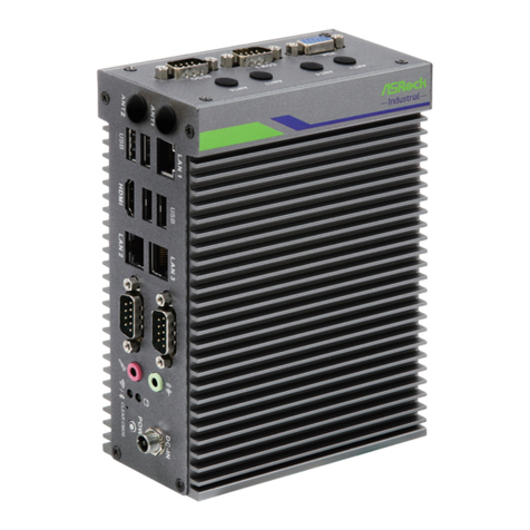
ASROCK iEP-7020E Series User manual

iEP-5000G Series
User Manual
Version 1.0
Published April 2022
iEP-7020E Series
iEP-7021E Series
iEP-7022E Series
iEP-7023E Series
User Manual

Version 1.0
Published July 2023
Copyright©2023 ASRock Industrial. All rights reserved.
Copyright Notice:
No part of this documentation may be reproduced, transcribed, transmitted, or translated
in any language, in any form or by any means, except duplication of documentation by the
purchaser for backup purpose, without written consent of ASRock Industrial Inc.
Products and corporate names appearing in this documentation may or may not be
registered trademarks or copyrights of their respective companies, and are used only for
identication or explanation and to the owners’ benet, without intent to infringe.
Disclaimer:
Specifications and information contained in this documentation are furnished for
informational use only and subject to change without notice, and should not be
constructed as a commitment by ASRock Industrial. ASRock Industrial assumes no
responsibility for any errors or omissions that may appear in this documentation.
With respect to the contents of this documentation, ASRock Industrial does not provide
warranty of any kind, either expressed or implied, including but not limited to the implied
warranties or conditions of merchantability or tness for a particular purpose.
In no event shall ASRock Industrial, its directors, ocers, employees, or agents be liable for
any indirect, special, incidental, or consequential damages (including damages for loss of
prots, loss of business, loss of data, interruption of business and the like), even if ASRock
Industrial has been advised of the possibility of such damages arising from any defect or
error in the documentation or product.
is device complies with Part 15 of the FCC Rules. Operation is subject to the following
two conditions:
(1) this device may not cause harmful interference, and
(2) this device must accept any interference received, including interference that may
cause undesired operation.
CALIFORNIA, USA ONLY
e Lithium battery adopted on this motherboard contains Perchlorate, a toxic substance
controlled in Perchlorate Best Management Practices (BMP) regulations passed by the
California Legislature. When you discard the Lithium battery in California, USA, please
follow the related regulations in advance.
“Perchlorate Material-special handling may apply, see www.dtsc.ca.gov/hazardouswaste/
perchlorate”
ASRock Industrial’s Website: www.asrockind.com

Important Safety Instructions
For user safety, please read and follow all instructions, Warnings, Cautions, and Notes
marked in this manual and on the associated device before handling/operating the device,
to avoid injury or damage.
1. Read these safety instructions carefully.
2. Retain this user manual for future reference.
3. Read the Specifications section of this manual for detailed information on the
recommended operating environment.
4. Disconnect the equipment from all AC outlets before cleaning. Use only a damp cloth
for cleaning. Do not use liquid or sprayed detergent.
5. Place the equipment on a reliable surface during installation. Dropping or letting the
equipment fall may cause damage.
6. Do not leave the equipment in an environment with a storage temperature of below
-40 °C (-40 °F) or above 85 °C (185 °F) as this may cause damage. The equipment
should be stored in a controlled environment.
7. Ensure that the voltage of the power source is correct before connecting the
equipment to a power outlet.
8. Position the power cord away from high-trac areas. Do not place anything over the
power cord.
9. If the equipment is not used for a long time, disconnect the equipment from the
power source to avoid damage from transient over-voltage.
10. All cautions and warnings on the equipment should be noted.
11. To avoid electrical shock and/or damage to device:
• Keep device away from water or liquid sources.
• Keep device away from high heat or humidity.
• Keep device properly ventilated (do not block or cover ventilation openings).
• Always use recommended voltage and power source settings.
• Always install and operate device near an easily accessible electrical outlet.
• Secure the power cord (do not place any object on/over the power cord).
• Only install/attach and operate device on stable surfaces and/or recommended
mountings.
• e power cord must be connected to a socket or outlet with a ground connection.
12. If one of the following occurs, have the equipment checked by service personnel:
• e power cord or plug is damaged.
• Liquid has penetrated into the equipment.
• e equipment has been exposed to moisture.
• The equipment is malfunctioning or does not operate according to the user
manual.
• e equipment has been dropped and damaged.

• e equipment shows obvious signs of breakage.
13. Never attempt to repair the device, which should only be serviced by qualified
technical personnel using suitable tools.
14. Any unverified component may cause unexpected damage. To ensure correct
installation, always use the components (e.g., screws) provided in the accessory box.
15. This equipment is not suitable for use in locations where children are likely to be
present.
16. e equipment should only be installed in a restricted access area.
17. Restricted Access Location : It is recommended that the device be installed only in a
server room or computer room where access is:
• Restricted to qualified service personnel or users familiar with restrictions
applied to the location, reasons therefor, and any precautions required.
• Only aorded by the use of a tool or lock and key, or other means of security, and
controlled by the authority responsible for the location.
• Be sure to turn off the power and then disconnect the power cords from your
system before performing any installation or servicing. A sudden surge of power
could damage sensitive electronic components.
• All interior servicing is to be performed by qualied skilled personnel only, which
requires the use of a tool for open the metal enclosure.
DIN Rail/Wall Mount: M3x5mm Screws (for securing the mounting bracket(s) to the chassis)
VESA Mount: M4x6mm Screws (for securing the VESA bracket to the monitor)
18. is model is intended to be supplied by an UL-certied power supply (Adapter: (1)
FSP/FSP120-ABAN3, (2) FSP/FSP330-AAAN3) suitable for use at TMA 40 °C (104
°F) min., and the output is rated 19 Vdc 3.42A min., ES1. (For FSP120-ABAN3) / 24
Vdc 13.75A min., ES1 (For FSP330-AAAN). If you need further assistance, contact
ASRock Industrial for additional information.
19. e terminal block is suitable for V+& V- for 14~28AWG. e torque value is 0.19Nm.
Use copper conductors only. Kindly note that this must be installed by a skilled
person.

Replaceable batteries
CAUTION : RISK OF EXPLOSION IF BATTERY IS REPLACED BY AN INCORRECT
TYPE. DISPOSE OF USED BATTERIES ACCORDING TO THE INSTRUCTIONS
BURN HAZARD
Hot surface! Do not touch! Touching this surface could result in bodily injury. To reduce
risk, allow the surface to cool before touching.
CAUTION
e equipment is equipped with a battery-powered real-time clock circuit. ere is a risk
of explosion if a battery is incorrectly replaced. Replace only with same or equivalent
type as recommended by the manufacturer. Discard all used batteries according to the
manufacturer’s instructions.
WARNING
All interconnection to the EUT is for indoor location and therefore PoE network
interconnected to the EUT is considered as ES1/SELV for connected only to PoE network
without routing to the outside plant.
WARNING
Input voltage rated 9-36V, 13.33-3.33A (For Basic SKU)
Input voltage rated 19-36V, 7.89-4.17A (For PoE SKU)
Input voltage rated 9-36V, 11.61-2.90A (For 5LAN SKU)
Input voltage rated 9-36V, 13.33-3.33A (For 5G SKU)
Packing: e unit should be carried with both hands and handled with care.
Maintenance: Use only approved products or a dry applicator to clean and maintain the
surfaces.

P/N: 15G062470000AK V1.0
*15G062470000AK*
Button Battery Safety Notice
- Remove and immediately recycle or dispose of used batteries according to local
regulations and keep away from children. Do NOT dispose of batteries in household
trash or incinerate.
- Even used batteries may cause severe injury or death.
- Call a local poison control center for treatment information.
- Battery type: CR2032
- Battery voltage: 3.3V
- Non-rechargeable batteries are not to be recharged.
- Do not force discharge, recharge, disassemble, heat above (manufacturer's specied
temperature rating) or incinerate. Doing so may result in injury due to venting,
leakage or explosion resulting in chemical burns.
- is product contains an irreplaceable battery.
- is icon indicates that a swallowed button battery can cause serious injury or death.
Please keep batteries out of sight or reach of children.
WARNING
•INGESTION HAZARD: This product contains a button cell or
coin battery.
•DEATHor serious injury can occur if ingested.
•A swallowed button cell or coin battery can cause Internal
Chemical Burns in as little as 2 hours.
•KEEP new and used batteries OUT OF REACH of CHILDREN
•Seek immediate medical attention if a battery is suspected to
be swallowed or inserted inside any part of the body.
Button Battery Safety Notice
Contact Information
If you need to contact ASRock Industrial or want to know more about ASRock Industrial,
you’re welcome to visit ASRock Industrial’s website at www.asrockind.com; or you may
contact your dealer for further information.
ASRock Industrial Incorporation
email: Info_ip[email protected]m
e terms HDMI®and HDMI High-Denition Multimedia Interface, and the HDMI logo are
trademarks or registered trademarks of HDMI Licensing LLC in the United States and other
countries.

Contents
Chapter 1 Introduction 1
1.1 Package Contents 1
1.2 Order Information 4
1.3 Optional Items 5
1.4 Product Specications 6
1.4.1 System : iEP-7020E-010 6
1.4.2 System : iEP-7021E-010 7
1.4.3 System : iEP-7022E-010 8
1.4.4 System : iEP-7023E-010 9
1.4.5 System : iEP-7020E-011 10
1.4.6 System : iEP-7021E-011 11
1.4.7 System : iEP-7022E-011 12
1.4.8 System : iEP-7023E-011 13
1.4.9 System : iEP-7020E-012 14
1.4.10 System : iEP-7021E-012 15
1.4.11 System : iEP-7022E-012 16
1.4.12 System : iEP-7023E-012 17
1.4.13 System : iEP-7020E-013 18
1.4.14 System : iEP-7021E-013 19
1.4.15 System : iEP-7022E-013 20
1.4.16 System : iEP-7023E-013 21
1.4.17 System : iEP-7020E-014 22
1.4.18 System : iEP-7021E-014 23

1.4.19 System : iEP-7022E-014 24
1.4.20 System : iEP-7023E-014 25
1.5 Block Diagram 26
Chapter 2 Product Overview 27
2.1 System Front Panel 27
2.1.1 System : iEP-7020E-010, iEP-7021E-010, iEP-7022E-010,
iEP-7022E-010 27
2.1.2 System : iEP-7020E-011/012/013/014,
iEP-7021E-011/012/013/014, iEP-7022E-011/012/013/014,
iEP-7023E-011/012/013/014 29
2.2 System Top Panel 32
2.2.1 System : iEP-7020E-010, iEP-7021E-010, iEP-7022E-010,
iEP-7023E-010 32
2.2.2 System : iEP-7020E-011/012/013, iEP-7021E-011/012/013,
iEP-7022E-011/012/013, iEP-7023E-011/012/013 34
2.2.3 System : iEP-7020E-014, iEP-7021E-014, iEP-7022E-014,
iEP-7023E-014 36
2.3 Inside View 38
2.4 Rear View 39
2.5 Right View (System : iEP-7020E-010, iEP-7021E-010,
iEP-7022E-010, iEP-7023E-010) 40
2.6 Position 41
Chapter 3 Hardware Installation 42
3.1 How to Install the Wi-Fi Module (2230) to
the M.2 Key E Slot (Optional) 42
3.2 How to Install the 4G LTE/5G Module (3042/3052/2280)
to the M.2 Key B Slot (Optional) 44
3.3 How to Install the M.2 SSD (2280) with the Heasink to

the M.2 Key M Socket 46
3.4 How to Install the Memory Modules and the Heatsinks 48
3.5 How to Install the 2.5-inch Storage Device
(For Basic SKU only) 50
3.6 How to Install the 5G Module/M2 PoE/M2 LAN Heatsink
(Optional) 52
3.7 How to Install a Nano SIM Dard and Micro SD Card 53
3.8 How to Install the Wall Mounting Bracket (Optional) 55
3.9 How to Install VESA Bracket (Optional)
(for iEP-7020E-010 Series) 57
3.10 How to Install the Din Rail Mounting Bracket (Optional) 58
3.11 How to Install Phoenix Connector and the Adapter
(Optional) 59
Chapter 4 Motherboard 60
4.1 Motherboard Layout 60
4.2 Jumpers Setup 63
4.3 Onboard Headers and Connectors 65
4.4 Expansion Slots (M.2 Sockets) 67
Chapter 5 UEFI Setup Utility 68
5.1 Introduction 68
5.1.1 Entering BIOS Setup 68
5.1.2 UEFI Menu Bar 69
5.1.3 Navigation Keys 70
5.2 Main Screen 71
5.3 Advanced Screen 72
5.3.1 CPU Conguration 73

5.3.2 Chipset Conguration 76
5.3.3 Intel(R) Time Coordinated Computing 78
5.3.4 Storage Conguration 80
5.3.5 Super IO Conguration 82
5.3.6 AMT Conguration 85
5.3.7 ACPI Conguration 87
5.3.8 USB Conguration 88
5.3.9 Trusted Computing 89
5.4 Hardware Health Event Monitoring Screen 91
5.5 Security Screen 92
5.6 Boot Screen 93
5.7 Exit Screen 94


iEP-7020E Series
PB 1
English
Chapter 1 Introduction
1.1 Package Contents
iEP-702XE-010 Series
• Intel® 13th Gen Core™ Industrial i7/i5 Processors (TDP 15W)
• Scalable power and performance in BGA for edge controller
• High performance Intel® Iris Xe Graphics architecture
• Fan-less and Rugged Design, Wide Temperature Operation (-40 °C to 70 °C)
• 9 to 36 VDC Wide Range Power Inputs
• Most Flexible IOs and Expansion for Industrial Applications
• 3 x Intel® I226-IT (2.5GbE)
• 3 x USB3 and 1 x USB2
• 4 x Serial Port (RS-232/422/485)
• Support Intel® IN-Band ECC
• Intel® TCC and TSN Support for Real-Time Computing
• Support Wi-Fi
iEP-702XE-011 Series
• Intel® 13th Gen Core™ Industrial i7/i5 Processors (TDP 15W)
• Scalable power and performance in BGA for edge controller
• High performance Intel® Iris Xe Graphics architecture
• Fan-less and Rugged Design, Wide Temperature Operation (-40 °C to 50 °C)
• 19 to 36 VDC Wide Range Power Inputs
• Most Flexible IOs and Expansion for Industrial Applications
• 3 x Intel® I226-IT (2.5GbE), 2 x Intel I210-AT (1GbE)
• Intel® I210-AT supports IEEE 802.3AF PoE
• 3 x USB3 and 1 x USB2
• 4 x Serial Port (RS-232/422/485)
• Support Intel® IN-Band ECC
• Intel® TCC and TSN Support for Real-Time Computing
• Support Wi-Fi
Because the hardware specications might be updated, the content of this documentation
will be subject to change without notice.

2 3
English
iEP-702XE-012 Series
• Intel® 13th Gen Core™ Industrial i7/i5 Processors (TDP 15W)
• Scalable power and performance in BGA for edge controller
• High performance Intel® Iris Xe Graphics architecture
• Fan-less and Rugged Design, Wide Temperature Operation (-40 °C to 70 °C)
• 9 to 36 VDC Wide Range Power Inputs
• Most Flexible IOs and Expansion for Industrial Applications
• 3 x Intel® I226-IT (2.5GbE), 2 x Intel I210-AT (1GbE)
• 3 x USB3 and 1 x USB2
• 4 x Serial Port (RS-232/422/485)
• Support Intel® IN-Band ECC
• Intel® TCC and TSN Support for Real-Time Computing
• Support Wi-Fi
iEP-702XE-013 Series
• Intel® 13th Gen Core™ Industrial i7/i5 Processors (TDP 15W)
• Scalable power and performance in BGA for edge controller
• High performance Intel® Iris Xe Graphics architecture
• Fan-less and Rugged Design, Wide Temperature Operation (-40 °C to 70 °C)
• 9 to 36 VDC Wide Range Power Inputs
• Most Flexible IOs and Expansion for Industrial Applications
• 3 x Intel® I226-IT (2.5GbE), 2 x Intel I210-AT (1GbE)
• 3 x USB3 and 1 x USB2
• 4 x Serial Port (RS-232/422/485)
• Support Intel® IN-Band ECC
• Intel® TCC and TSN Support for Real-Time Computing
• Support 4G LTE/5G
iEP-702XE-014 Series
• Intel® 13th Gen Core™ Industrial i7/i5 Processors (TDP 15W)
• Scalable power and performance in BGA for edge controller
• High performance Intel® Iris Xe Graphics architecture
• Fan-less and Rugged Design, Wide Temperature Operation (-40 °C to 70 °C)
• 9 to 36 VDC Wide Range Power Inputs
• Most Flexible IOs and Expansion for Industrial Applications
• 3 x Intel® I226-IT (2.5GbE)
• 3 x USB3 and 1 x USB2
• 4 x Serial Port (RS-232/422/485)
• Support Intel® IN-Band ECC

iEP-7020E Series
2 3
English
If any items are missing or appear damaged, contact your authorized dealer.
• Intel® TCC and TSN Support for Real-Time Computing
• Support Wi-Fi
• Support 4G LTE/5G

4 5
English
Model Name PN SKU CPU Description
iEP-7020E-010 90PXG9E0-00000000 Basic SKU i7-1365URE
(15W)
W/O RAM, SSD,
ADAPTOR
IEP-7020E-011 90PXG9E0-10000000 PoE SKU i7-1365URE
(15W)
W/O RAM, SSD,
ADAPTOR
IEP-7020E-012 90PXG9E0-20000000 5LAN-WIFI
SKU
i7-1365URE
(15W)
W/O RAM, SSD,
ADAPTOR
IEP-7020E-013 90PXG9E0-30000000 5LAN-5G
SKU
i7-1365URE
(15W)
W/O RAM, SSD,
ADAPTOR
IEP-7020E-014 90PXG9E0-40000000 5G-WIFI
SKU
i7-1365URE
(15W)
W/O RAM, SSD,
ADAPTOR
iEP-7021E-010 90PXGBX0-01000000 Basic SKU i5-1345URE
(15W)
W/O RAM, SSD,
ADAPTOR
IEP-7021E-011 90PXGBX0-11000000 PoE SKU i5-1345URE
(15W)
W/O RAM, SSD,
ADAPTOR
IEP-7021E-012 90PXGBX0-21000000 5LAN-WIFI
SKU
i5-1345URE
(15W)
W/O RAM, SSD,
ADAPTOR
IEP-7021E-013 90PXGBX0-31000000 5LAN-5G
SKU
i5-1345URE
(15W)
W/O RAM, SSD,
ADAPTOR
IEP-7021E-014 90PXGBX0-41000000 5G-WIFI
SKU
i5-1345URE
(15W)
W/O RAM, SSD,
ADAPTOR
iEP-7022E-010 90PXGBV0-02000000 Basic SKU i7-1370PRE
(28W)
W/O RAM, SSD,
ADAPTOR
IEP-7022E-011 90PXGBV0-12000000 PoE SKU i7-1370PRE
(28W)
W/O RAM, SSD,
ADAPTOR
IEP-7022E-012 90PXGBV0-22000000 5LAN-WIFI
SKU
i7-1370PRE
(28W)
W/O RAM, SSD,
ADAPTOR
IEP-7022E-013 90PXGBV0-32000000 5LAN-5G
SKU
i7-1370PRE
(28W)
W/O RAM, SSD,
ADAPTOR
IEP-7022E-014 90PXGBV0-42000000 5G-WIFI
SKU
i7-1370PRE
(28W)
W/O RAM, SSD,
ADAPTOR
iEP-7023E-010 90PXGBW0-03000000 Basic SKU i5-1350PRE
(28W)
W/O RAM, SSD,
ADAPTOR
IEP-7023E-011 90PXGBW0-13000000 PoE SKU i5-1350PRE
(28W)
W/O RAM, SSD,
ADAPTOR
IEP-7023E-012 90PXGBW0-23000000 5LAN-WIFI
SKU
i5-1350PRE
(28W)
W/O RAM, SSD,
ADAPTOR
IEP-7023E-013 90PXGBW0-33000000 5LAN-5G
SKU
i5-1350PRE
(28W)
W/O RAM, SSD,
ADAPTOR
IEP-7023E-014 90PXGBW0-43000000 5G-WIFI
SKU
i5-1350PRE
(28W)
W/O RAM, SSD,
ADAPTOR
1.2 Order Information

iEP-7020E Series
4 5
English
1.3 Optional Items
Model Name PN Description
Wall Mount
Kits
13G020760000AI Attach the wall mounting brackets to the iEP-
7020E Series.
Din Rail Kits 13G020761000AI Attach the din-rail brackets to the iEP-7020E
Series and can place to the din rail.
Wall Mount Kit 13G0207860A0AI Attach the wall mounting brackets to the iEP-
7020E-000 system.
VESA Mount
Kit
13G020554010AI Attach the VESA mount brackets to the iEP-
7020E-000 system.
4G/5G Module
Sink Kits
13G020786060AI e design of heatsink to reduce 4G or 5G module
temperatures for optimal performance.
4G Module Kits 14G15A004000AI Antenna x2
14G000035300AI SMA CABLE MHF-4 不帶針 , L=180mm x1
14G000035310AI SMA CABLE MHF-4 不帶針 , L=300mm x1
5G Module Kits 14G15A004000AI Antenna x4
14G000035300AI SMA CABLE MHF-4 不帶針 , L=180mm x2
14G000035310AI SMA CABLE MHF-4 不帶針 , L=300mm x2
Wi-Fi Module
Kits
14G15A005000AI Antenna x2
14G000032200AI WIFI SMA CABLE 帶針 , L=185mm x2
Adapter 04G266001001AI ADAPTER 120W 19V W/O CONN (For
Basic/5LAN/5G SKU)
04G266001200AI ADAPTER 330W 19V W/O CONN (For PoE
SKU)

6 7
English
1.4 Product Specications
1.4.1 System : iEP-7020E-010
Processor
CPU Intel® Core™ i7-1365URE
Frequency 1.70 GHz
TDP 15W
BIOS AMI EFI 256 Mbit
Memory
Technolog y DDR4 3200 MHz (Support In-Band ECC)
Max Capacity 64GB
Socket Dual 260-pin SO-DIMM
Graphics Chipset Intel® Iris Xe Graphics
Interface 2 x DP++ 1.4a
Expansion
Slots
RF&Antenna 7 x Antenna Hole
M.2
1 x M.2 3042/3052/2280 Key B (PCIe Gen3x1/USB3.2
mode)
- Support SATA3 SSD Storage
1 x M.2 2230 Key E (CNVi/PCIe Gen3x1/USB2.0 mode)
- Support Wi/BT Module
SIM Slot 1 x Nano SIM Card
SD Slot 1 x Micro SD Card (SD specication v3.0 UHS-I: SDR25/
SDR50)
Audio Interface Realtek ALC897, High Denition Audio, Mic-In, Line-Out
Ethernet
LAN1 Intel I226-IT, 2.5 GbE
LAN2 Intel I226-IT, 2.5 GbE
LAN3 Intel I226-IT, 2.5 GbE
Storage M.2 1 x M.2 2280 Key M (PCIe Gen4x4)
2.5"SSD 1 x 2.5" 9.5mm SATA3 SSD
I/O Interface
Serial Port 4 x RS-232/422/485 (9-pin D-sub connector)
GPIO 8-bit Programmable DIO
USB 3 x USB3.2 Gen2, 1 x USB2
Function
1 x Reset button
1 x Power on button with LED
2 x Diagnostic LED
Security Watch Dog 255-level timer interval, set up through soware
TPM TPM 2.0
Power
Requirement DC Input 1 x 3-pin phoenix type DC-IN in 9-36V DC
Environment
Operating
Temp. -40°C ~ 70°C (-40°F~158°F), w/airow 0.5~0.8m/s
Storage Temp. -40°C ~ 85°C (-40°F~185°F)
Humidity ~95% @ 40°C (non-condensing)
Shock Operating with SSD: 100 G, half sine 11 ms duration
Vibration Operating with SSD: 5 Grms, 5-500 Hz, 3 axes
ESD Contact +/-8 KV, Air +/-15 KV
EMC CE and FCC Class A (EN61000-6-4/-2)
Safety LVD
Mechanical
Mounting Din-Rail, Wall Mount, VESA Mount (Optional)
Dimensions 58mm (W) x 134mm (D) x 170mm (H)
Net Weight 1.57 kg
OS Windows 10, Ubuntu22.04 LTS
Real-Time
Enablement TSN, TCC support under Linux

iEP-7020E Series
6 7
English
1.4.2 System : iEP-7021E-010
Processor
CPU Intel® Core™ i5-1345URE
Frequency 1.40 GHz
TDP 15W
BIOS AMI EFI 256 Mbit
Memory
Technolog y DDR4 3200 MHz (Support In-Band ECC)
Max Capacity 64GB
Socket Dual 260-pin SO-DIMM
Graphics Chipset Intel® Iris Xe Graphics
Interface 2 x DP++ 1.4a
Expansion
Slots
RF&Antenna 7 x Antenna Hole
M.2
1 x M.2 3042/3052/2280 Key B (PCIe Gen3x1/USB3.2
mode)
- Support SATA3 SSD Storage
1 x M.2 2230 Key E (CNVi/PCIe Gen3x1/USB2.0 mode)
- Support Wi/BT Module
SIM Slot 1 x Nano SIM Card
SD Slot 1 x Micro SD Card (SD specication v3.0 UHS-I: SDR25/
SDR50)
Audio Interface Realtek ALC897, High Denition Audio, Mic-In, Line-Out
Ethernet
LAN1 Intel I226-IT, 2.5 GbE
LAN2 Intel I226-IT, 2.5 GbE
LAN3 Intel I226-IT, 2.5 GbE
Storage M.2 1 x M.2 2280 Key M (PCIe Gen4x4)
2.5"SSD 1 x 2.5" 9.5mm SATA3 SSD
I/O Interface
Serial Port 4 x RS-232/422/485 (9-pin D-sub connector)
GPIO 8-bit Programmable DIO
USB 3 x USB3.2 Gen2, 1 x USB2
Function
1 x Reset button
1 x Power on button with LED
2 x Diagnostic LED
Security Watch Dog 255-level timer interval, set up through soware
TPM TPM 2.0
Power
Requirement DC Input 1 x 3-pin phoenix type DC-IN in 9-36V DC
Environment
Operating
Temp. -40°C ~ 70°C (-40°F~158°F), w/airow 0.5~0.8m/s
Storage Temp. -40°C ~ 85°C (-40°F~185°F)
Humidity ~95% @ 40°C (non-condensing)
Shock Operating with SSD: 100 G, half sine 11 ms duration
Vibration Operating with SSD: 5 Grms, 5-500 Hz, 3 axes
ESD Contact +/-8 KV, Air +/-15 KV
EMC CE and FCC Class A (EN61000-6-4/-2)
Safety LVD
Mechanical
Mounting Din-Rail, Wall Mount, VESA Mount (Optional)
Dimensions 55mm (W) x 134mm (D) x 170mm (H)
Net Weight 1.57 kg
OS Windows 10, Ubuntu22.04 LTS
Real-Time
Enablement TSN, TCC support under Linux

8 9
English
1.4.3 System : iEP-7022E-010
Processor
CPU Intel® Core™ i7-1370PRE
Frequency 1.9 GHz
TDP 28W
BIOS AMI EFI 256 Mbit
Memory
Technolog y DDR4 3200 MHz (Support In-Band ECC)
Max Capacity 64GB
Socket Dual 260-pin SO-DIMM
Graphics Chipset Intel® Iris Xe Graphics
Interface 2 x DP++ 1.4a
Expansion
Slots
RF&Antenna 7 x Antenna Hole
M.2
1 x M.2 3042/3052/2280 Key B (PCIe Gen3.1/USB3.2
mode)
- Support SATA3 SSD Storage
1 x M.2 2230 Key E (CNVi/PCIe Gen3.1/USB2.0 mode)
- Support Wi/BT Module
SIM Slot 1 x Nano SIM Card
SD Slot 1 x Micro SD Card (SD specication v3.0 UHS-I: SDR25/
SDR50)
Audio Interface Realtek ALC897, High Denition Audio, Mic-In, Line-Out
Ethernet
LAN1 Intel I226-IT, 2.5 GbE
LAN2 Intel I226-IT, 2.5 GbE
LAN3 Intel I226-IT, 2.5 GbE
Storage M.2 1 x M.2 2280 Key M (PCIe Gen4x4)
2.5"SSD 1 x 2.5" 9.5mm SATA3 SSD
I/O Interface
Serial Port 4 x RS-232/422/485 (9-pin D-sub connector)
GPIO 8-bit Programmable DIO
USB 3 x USB3.2 Gen2, 1 x USB2
Function
1 x Reset button
1 x Power on button with LED
2 x Diagnostic LED
Security Watch Dog 255-level timer interval, set up through soware
TPM TPM 2.0
Power
Requirement DC Input 1 x 3-pin phoenix type DC-IN in 9-36V DC
Environment
Operating
Temp. -40°C ~ 70°C (-40°F~158°F), w/airow 0.5~0.8m/s
Storage Temp. -40°C ~ 85°C (-40°F~185°F)
Humidity ~95% @ 40°C (non-condensing)
Shock Operating with SSD: 100 G, half sine 11 ms duration
Vibration Operating with SSD: 5 Grms, 5-500 Hz, 3 axes
ESD Contact +/-8 KV, Air +/-15 KV
EMC CE and FCC Class A (EN61000-6-4/-2)
Safety LVD
Mechanical
Mounting Din-Rail, Wall Mount, VESA Mount (Optional)
Dimensions 55mm (W) x 134mm (D) x 170mm (H)
Net Weight 1.57 kg
OS Windows 10, Ubuntu22.04 LTS
Real-Time
Enablement TCC support under Linux

iEP-7020E Series
8 9
English
1.4.4 System : iEP-7023E-010
Processor
CPU Intel® Core™ i5-1350PRE
Frequency 1.8 GHz
TDP 28W
BIOS AMI EFI 256 Mbit
Memory
Technolog y DDR4 3200 MHz (Support In-Band ECC)
Max Capacity 64GB
Socket Dual 260-pin SO-DIMM
Graphics Chipset Intel® Iris Xe Graphics
Interface 2 x DP++ 1.4a
Expansion
Slots
RF&Antenna 7 x Antenna Hole
M.2
1 x M.2 3042/3052/2280 Key B (PCIe Gen3.1/USB3.2
mode)
- Support SATA3 SSD Storage
1 x M.2 2230 Key E (CNVi/PCIe Gen3.1/USB2.0 mode)
- Support Wi/BT Module
SIM Slot 1 x Nano SIM Card
SD Slot 1 x Micro SD Card (SD specication v3.0 UHS-I: SDR25/
SDR50)
Audio Interface Realtek ALC897, High Denition Audio, Mic-In, Line-Out
Ethernet
LAN1 Intel I226-IT, 2.5 GbE
LAN2 Intel I226-IT, 2.5 GbE
LAN3 Intel I226-IT, 2.5 GbE
Storage M.2 1 x M.2 2280 Key M (PCIe Gen4x4)
2.5"SSD 1 x 2.5" 9.5mm SATA3 SSD
I/O Interface
Serial Port 4 x RS-232/422/485 (9-pin D-sub connector)
GPIO 8-bit Programmable DIO
USB 3 x USB3.2 Gen2, 1 x USB2
Function
1 x Reset button
1 x Power on button with LED
2 x Diagnostic LED
Security Watch Dog 255-level timer interval, set up through soware
TPM TPM 2.0
Power
Requirement DC Input 1 x 3-pin phoenix type DC-IN in 9-36V DC
Environment
Operating
Temp. -40°C ~ 70°C (-40°F~158°F), w/airow 0.5~0.8m/s
Storage Temp. -40°C ~ 85°C (-40°F~185°F)
Humidity ~95% @ 40°C (non-condensing)
Shock Operating with SSD: 100 G, half sine 11 ms duration
Vibration Operating with SSD: 5 Grms, 5-500 Hz, 3 axes
ESD Contact +/-8 KV, Air +/-15 KV
EMC CE and FCC Class A (EN61000-6-4/-2)
Safety LVD
Mechanical
Mounting Din-Rail, Wall Mount, VESA Mount (Optional)
Dimensions 55mm (W) x 134mm (D) x 170mm (H)
Net Weight 1.57 kg
OS Windows 10, Ubuntu22.04 LTS
Real-Time
Enablement TCC support under Linux
This manual suits for next models
43
Table of contents
Other ASROCK Controllers manuals