Securitron®AQL4
Intelligent Power System
Quick Start Guide
Overview
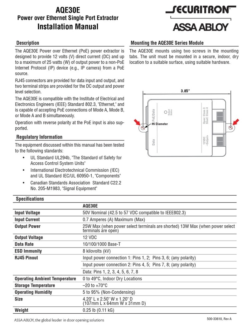
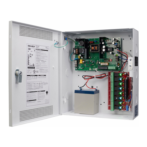
1 AC Voltage Select Jumper – Leave INTACT
for 120 V input. CUT for 230 V input.
Failure to cut this jumper when using the Securitron AQL
with a 230 VAC input will result in damage to the system.
2 AC Input primary AC connection.
3 AC On LED (GREEN) – Indicates a valid
AC input voltage is present. Missing AC is
indicated by this LED extinguishing.
WARNING: Always confirm the absence of AC power
with a meter before servicing to prevent electric shock.
4 Voltage Selection Jumper – Selects the
output voltage between 12 V and 24 VDC.
WARNING: Remove AC input power before changing
the voltage select switch to avoid damaging
the power supply or connected equipment.
5 FAI LED (RED) – Indicates activation
of the Fire Alarm Input.
6 FlexIO Connector – Supplies FAI status
to any accessory boards. Receives fault
signal from accessory boards.
7 FAI & Charge Current Configuration Switches
SWITCH 1
FAI Selection
SWITCH 2
Charge Current
OFF = Constant Output OFF = High Charge Current
ON = Output switches on FAI ON = Low Charge Current
8 System Fault Contact – Contact labeling
is adjacent to the terminals and shown in
the unpowered (FAULT) condition.
9 AC Fault Contact – Contact labeling is
adjacent to the terminals and shown in the
unpowered (FAULT) condition. AC fault is
indicated on a missing AC Input voltage.
10 Auxiliary Voltage – A fixed Class 2 DC output.
11 FAI Input – The input from the FACP. Can be wired to
accept a NO, NC, Open Collector, or Voltage input.
12 Battery Terminal Connection – For the
optional battery backup. Battery set voltage
must match the DC output voltage setting.
13 Main DC Output – Of the power supply. The
output can either be constant or switched based
on the configuration setting of Switch 1.
NOTE: The DC ON LED will be green with voltage
present, if set to 12 VDC or blue if set to 24 VDC.
14 DataLink Connection – This connector allows
optional programming and monitoring of the
Securitron AQL power supply via an optional
NetLink network module. See the instructions
for the Netlink module for more information.
1
2
3
6
45
7
11
8
9
10
12
13
14
Observe battery
polarity or damage
may result
For UL compliance, the AC fault contact must
be monitored by a listed control panel
Specifications and more details
found in the full manual here.
(Downloadable pdf)
