Assun AM-PI2858AN Series User manual

Assun Motor
Product Manual
For DC Servo Motor
of
AM-PI2858AN Series
1st edition. October, 2019.
All Rights Reserved
Assun Motor Inc.
Assun Motor Pte Ltd
Shenzhen Zhengyuan Motor Co., Ltd

2/ 13
Contents
Assun Motor...........................................................................................................................................................1
Product Manual......................................................................................................................................................1
1. About the Manual...........................................................................................................................................3
1.1 Validity of This Document .........................................................................................................3
1.2 Using This Document..................................................................................................................3
1.3 Definition of Terms ......................................................................................................................4
1.4 Definition of Symbols..................................................................................................................4
2. Product Safety..................................................................................................................................................5
2.1 Intended Product Usage...................................................................................................................5
2.2 Product Usage Safety ........................................................................................................................5
2.3 Product Disposal/Recycling .............................................................................................................7
3. Product Series Information..........................................................................................................................8
3.1 Product Series Structure Introduction..........................................................................................8
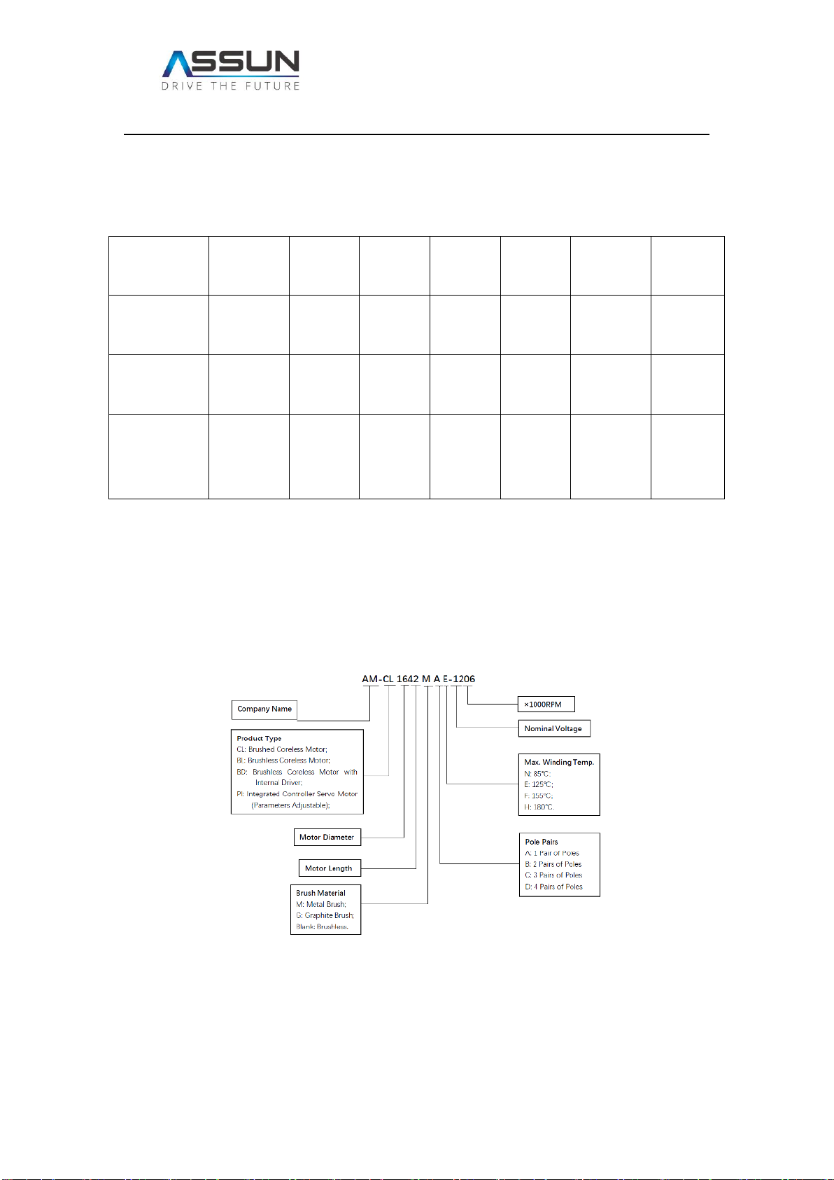
3.2 Product Model Information.............................................................................................................9
4. Product Function and Usage ................................................................................................................... 10
4.1 Motor Installation and Power Connection............................................................................... 10
4.2 Pulse input.......................................................................................................................................... 11
4.3 CW/CCW Control............................................................................................................................. 11
4.4 Feedback Pulse ................................................................................................................................. 11
5. Maintenance.................................................................................................................................................. 12
Appendix ............................................................................................................................................................. 12
Appendix 1. Series Product Parameters .......................................................................................... 12
Appendix 2. Specified Product Drawing and Parameters ......................................................... 12
Contact................................................................................................................................................................. 12

3/ 13
1. About the Manual
1.1 Validity of This Document
The product manual document here is used for AM-PI2858AN Series product by Assun Motor
which is DC brushless motor with integrated position servo controller. The manual has made
detailed description to the safety and functional usage of this motor product series. It helps
the professional user to install and connect the motor, and also guide the user in relevant
control function usage.
All data in this manual are based on the actual manufacturing and standard testing condition
of AM-PI2858AN Series product. Standard testing condition is when the motor installed
horizontally and environment temperature is 25℃.
For relevant parameter summaries of the product series, please refer to Appendix 1 “Product
Series Parameters”; For specified standard model or customized model, please refer to
Appendix 2 “Detailed Product Drawing and Parameter”.
1.2 Using This Document
Please read this document carefully before install and set-up the product. Please pay extra
attention to the second chapter “Product Safety”, and strictly follow the warnings and
instructions.
Please retain this document throughout the entire working life of the product, and keep the
document accessible to the operating and, if necessary, maintenance personnel at all times.
Pass a copy of this document on to any subsequent owner or user of the product.

4/ 13
1.3 Definition of Terms
Term
Meaning
PWM
Pulse Width Modulation
CW/CCW
Clockwise/Counter Clockwise
Feedback Pulse
Pulses give out per revolution
VIL/VIH
Voltage Input Low / Voltage Input High
Pin
Control Function Connect Pin
Cable
Power Connection Cable
GND
Ground / Negative Pole
Vcc
Direct Current Voltage
RPM
Revolution per Minute
1.4 Definition of Symbols
Caution! Hazard to persons. Disregard may lead to injury.
Warning! Improper operation will cause product damage.
Caution! Hazardous due to hot surface. Disregard may lead to burns.

5/ 13
2. Product Safety
2.1 Intended Product Usage
The Assun Motor AM-PI2858AN Series integrated DC servo motor product, which we are
describing here in this manual, are used for rotating power output under rated DC supply and
suitable pulse control. Position control function is integrated so it could be used in multiple
servo drive systems such as industrial automation and actuators. Direction, speed and position
control functions could be achieved with upper PLC system.
The product must be properly installed when in use, and shall be operated in an environment
with good heat dissipation conditions. In normal installation condition, when the operational
parameters have not exceeded the maximum continuous values, winding temperature must
be maintained below 85℃. The product can be used alone or coupled to a gearbox to achieve
ideal output torque and RPM.
The product is not suitable for operation in environments with high humid or excessive dust.
During the operation, please follow the parameter limits in the appendices to adjust the power
supply and running state, so as to achieve the optimum operational output and longest
product lifetime.
For usage of product in special environment, please contact our local sales or service staff for
consultancy and get the relevant advice or customized service.
This product is NOT SUITABLE for applications where the failure of the product could result
in the death of an individual or group of individuals.
2.2 Product Usage Safety
The product is a high-speed rotating device. Please make sure the product is properly
mounted before commencement of operation to prevent potential hazards to people or
equipment. Please refer to Chapter 4.1 of this manual for further installation guidance.

6/ 13
Motor surface temperature could be high after long term operation. Please exercise caution
when touching or handling the product.
Power supply must be filtered DC. The input voltage shall be within the rated value for normal
operation. Voltage cannot be lower than 10V for lower voltage operation. Voltage cannot
exceed the rated value for long term operation and shall be always under 28V.
Power supply connection must be strictly according to the designated positive and
negative polarity. If the power supply is reversed, it will seriously damage the internal
driver and lead to malfunction of the motor. Red cable from motor shall connect to the
positive of power supply, blue cable from motor shall connect to the negative of power
supply. For detailed power connection guidance, refer to Chapter 4.1.
Please install the motor in an environment with good heat sinking and/or ventilation.
Inadequate heat dissipation will lead to the motor winding temperature exceeding the limit
of 85℃ and will cause thermal damage to the internal electronic parts and winding, resulting
in motor malfunction and/or failure.

7/ 13
Please use the motor according to the parameter limits in the appendix, otherwise it may
cause the motor to be exceed current limits or overheat, which could lead to irreversible
damage to the motor.
The motor is not suitable for operating in high humid and dusty environments. High humidity
or excessive dust concentration could lower the motor performance and shorten the motor
lifetime.
The product is a precision Brushless DC motor with sensitive internal electronic components.
Please do not personally disassemble the product.
2.3 Product Disposal/Recycling
This series of motor products is manufactured with multiple types of metals, alloy materials,
chemical adhesives and lubricants. Please dispose it properly as recyclable material. For a
detailed product material listing please refer to Chapter 3.1.

8/ 13
3. Product Series Information
3.1 Product Series Structure Introduction
AM-PI2858AN Series products is a series of precision DC servo motors with integrated
electronics and inner rotating rotor. Case diameter is φ28mm, case length is 58mm, rated
power around 30W, with a net weight of approximately 155g. For detailed series information
and parameters please refer to Appendix 1.
The series product is inner rotor brushless dc motor, relying on the internal driver electronics
to energize the stator winding in sequence to make the magnetic poles rotate and thus attract
the permanent magnetic rotors to rotate in synchronization. The product's basic structure is
depicted in illustration 1.
Illustration 1. Exploded Product View

9/ 13
This series of product are manufactured using materials using multi-types of metal, alloy
material and chemical products. Specific material usage as shown in Table 1.
Table 1. Product Material Matrix
Components
End Cover
Winding
Bearing
Rotor
Magnet
Rotor
Shaft
Housing
Cable
Core
Material
Stainless
Steel
Copper
Stainless
Steel
Sintered
NdFeB
Stainless
Steel
Aluminum
Alloy
Copper
Components
Cable
Insulation
PCB
Board
PCB
Circuit
Glue
Grease
Cushion
Other
Materials
Material
Plastic
(Teflon)
Glass
Fiber &
Copper
Copper
Epoxy
Resin
Fluorine
Grease
Stainless
Steel
Precious
Metals;
Silicon.
3.2 Product Model Information
To make it convenient for the customer to choose a specific part number or model and
understand the part number methodology, please refer below in Illustration 2 the explanation
for model number composition principle.
Illustration 2. Part Number Nomenclature
Customers can choose suitable products based on their types and characteristics shown in
the part number methodology. If products with special characteristics are required, please
contact our regional sales person for customized service.

10 / 13
4. Product Function and Usage
The Product Series has five control cables and two power supply cables.
Two power cables are red cable (connect to power supply positive) and blue cable (connect
to power supply negative).
Five control cables include ground cable (black), rotating direction control (white), feedback
pulse (green), pulse input cable (white) and enable input (yellow). These cables are enclosed
in a black shielding cable for better stability. Analogue voltage input is defined as low voltage
input to be 0-1.2V and high voltage input to be 22-24V.
The enable input must be supplied with low voltage or connected to GDN for the motor to
operate. Motor rotating speed controlled by pulse input. Commonly the control wiring
diagram are proposed as following:
4.1 Motor Installation and Power Connection
Motor must be properly and securely mounted., typically utilizing the treaded holes in the
front cover to fix the motor. It will be proposed to install the motor to metal parts, or installed
in well ventilated environments for better heat dissipation.
There are two AWG22# power cables, one is red cable that should be connected to the
positive of power supply, the other is blue cable which should be connected to the negative
of power supply. The power connection must obey the indication above. If the power supply
is inadvertently reversed, it will seriously damage the internal driver causing malfunction of
the motor.

11 / 13
4.2 Pulse input
The red cable is for pulse input from PLC system, and Max frequency at 60KHz. The motor
will rotate one revolution for every 256 input pulses. For one pulse given, motor will rotate
1/256 revolution, which is 1.4°, tolerance at ±0.3°.
Under rated or lower torque, the motor will keep a steady speed of rated speed. When load
torque over rated value, there will be some variance of speed but basically motor keep the
speed steady. Over load torque shall not be higher than 50 mN·m or last longer than 3
seconds, otherwise the motor may overheat and cause malfunctions.
4.3 CW/CCW Control
Yellow pin is for rotating direction control. Clockwise and counter clockwise rotation of the
motor shaft is defined when looking from the front shaft side, looking down on the mounting
surface.
In high voltage level, then the motor rotates clockwise. If the voltage level is low, then motor
rotates counter-clockwise.
When the cable is not connected, it is same as high voltage level and motor rotates clockwise;
when the cable is connected to ground cable, it is same as low voltage level and motor rotates
counter-clockwise.
CAUTION do not reverse the motor direction while the motor is rotating! It is highly
recommended to stop the motor before reversing motor rotational direction.
4.4 Feedback Pulse
For the red cable, it will give 32 pulses per revolution as feedbacks to the PLC system, and
could be used for monitoring motor operation condition.

12 / 13
5. Maintenance
The product series is maintenance free, please do not disassemble in person. There are no
repairable components inside the motor. Regarding any quality issue or maintenance needs,
please contact our regional service person for relevant technical support.
Ignoring this warning will void the warranty.
Appendix
Appendix 1. Series Product Parameters
Appendix 2. Specified Product Drawing and Parameters
Contact
Singapore
Tel: +65 6532-5243
Email: info@assunmotor.com
Add: #06-05, 1092 Lower Delta Road. Singapore 169203.
China

13 / 13
Tel: +86 755-8368-8818
Email: info@assunmotor.com
Add: 7th Floor, Blk 6, Yongping Industrial Area, 9 Tongfu Road. Shenzhen, P.R.China.
USA
Tel: +1 760-451-2723
Email: beauche@roadrunner.com
Add: Suit F208, 6370 Lusk Boulevard San Diego, CA 92121-2760 USA
Table of contents
Popular Industrial Equipment manuals by other brands

Di-soric
Di-soric OGWTI-100G3-T4 manual

Adaptive Micro Systems
Adaptive Micro Systems Alpha 4000 RGB MNS B Series installation manual

YASKAWA
YASKAWA DeviceNet SI-N3 installation manual

Curtis Dyna-Fog
Curtis Dyna-Fog MAXI-PRO 4 manual

IST
IST ISTpure SR30-30V installation guide

HOLZMANN MASCHINEN
HOLZMANN MASCHINEN ZX7045 operating manual