Page 4
UNSWITCHED
ORG (277V)
BLK (120V)
WHT/BLK
5
COMMON
WHITE
VIOLET
VIOLET
SWITCHED OR
UNSWITCHED LINE
LAMP
*LAMP
BLACK
WHITE BLUE
BLUE
RED
RED
YELLOW
YELLOW
BLUE
BLUE/WHT
RED/WHT
RED
YELLOW
UNIT
CONNECTOR
TBTS / CHARGE
INDICATOR
COMMON
A.C.
Ballast
EMERGENCY
BALLAST
2LRSB_E
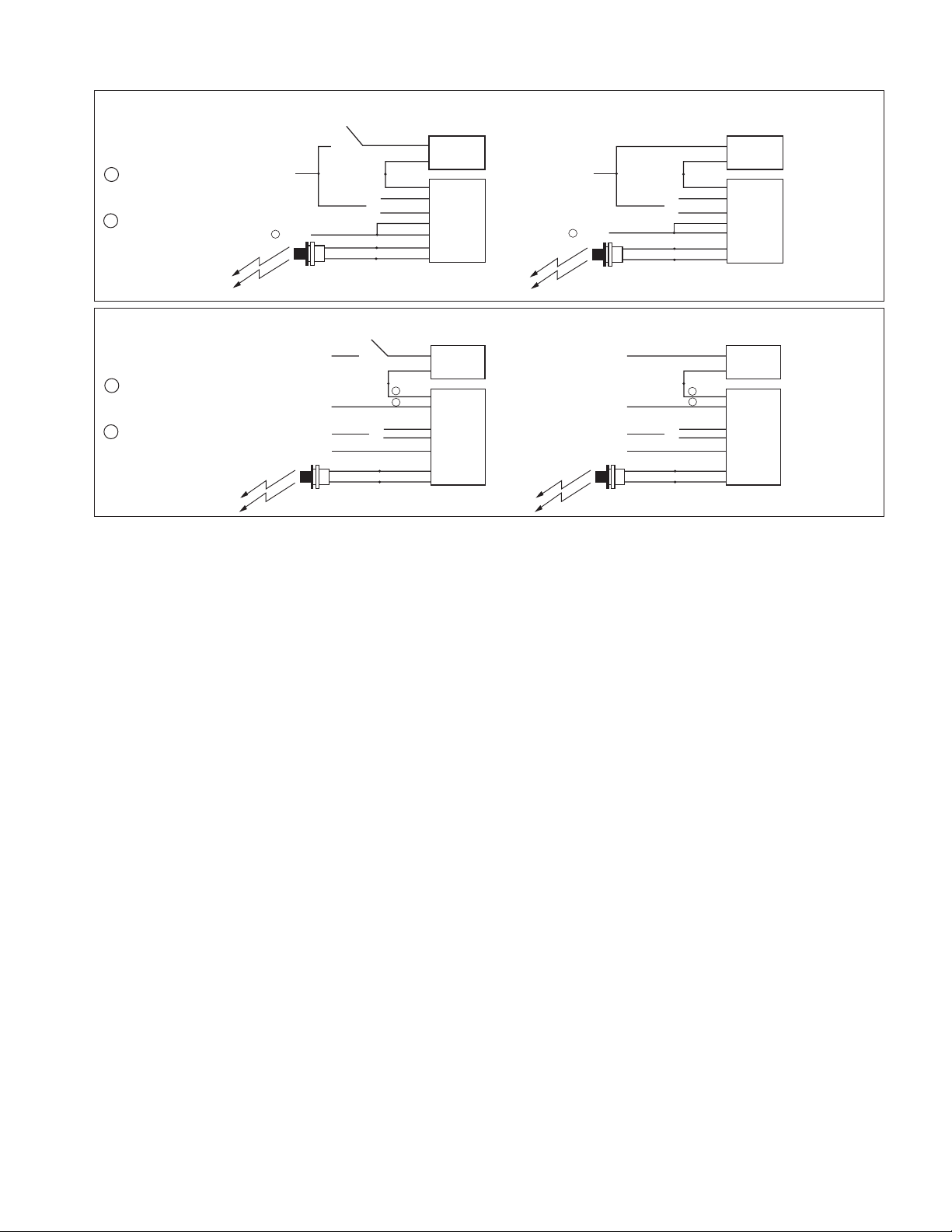
TWO LAMP RAPID START BALLAST
WHT/BLK
WHT/RED
RED OR
RED/BLK (+)
SELECT PROPER VOLTAGE
LEAD. CAP UNUSED LEAD. REFER TO
AC INPUT WIRING ON ILLUSTRATION 3
OF INSTALLATION MANUAL FOR PROPER
INPUT CIRCUIT WIRING.
DO NOT MATE CONNECTOR UNTIL
INSTALLATION IS COMPLETE AND
AC POWER IS SUPPLIED.
LAMP SELECTOR LEADS—REFER
TO INSTALLATION INSTRUCTIONS,
LAMPS OPERATION SECTION FOR
VARIOUS OPTIONS
TEST ACCESSORY LEADS-
REFER TO INSTALLATION
INSTRUCTIONS FOR PROPER
POLARITY WIRING.
5USE EITHER WHT/BLK LEAD
FOR WIRING THE COMMON.
REFER TO AC INPUT WIRING
ON ILLUSTRATION 3 OF
INSTALLATION MANUAL.
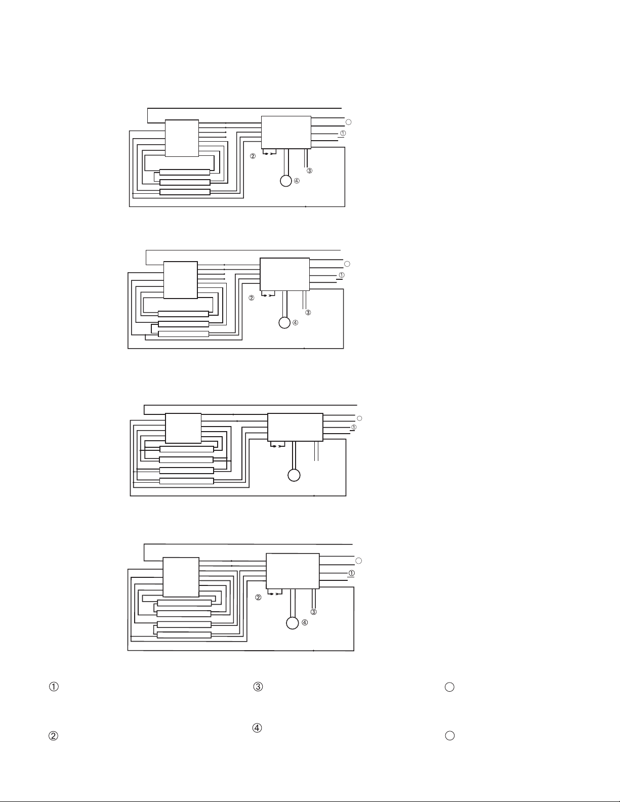
TYPICAL WIRING DIAGRAMS
For wiring diagrams of ballasts not shown, consult our Customer Service.
Rev. 1506
68322-551
1. ONE LAMP RAPID START BALLAST
2. TWO LAMP RAPID START BALLAST
3. TWO LAMP RAPID START BALLAST
4. THREE LAMP RAPID START BALLAST
5. ONE LAMP INSTANT START BALLAST
6. TWO LAMP INSTANT START BALLAST
7. THREE LAMP INSTANT START BALLAST
8. FOUR LAMP INSTANT START BALLAST
UNSWITCHED
ORG (277V)
BLK (120V)
WHT/BLK
5
COMMON
WHITE
VIOLET
VIOLET
SWITCHED OR
UNSWITCHED LINE
*LAMP
*AC / EMERGENCY
BLACK
WHITE BLUE
BLUE
RED
RED
BLUE
BLUE/WHT
RED/WHT
RED
YELLOW
UNIT
CONNECTOR
TBTS / CHARGE
INDICATOR
COMMON
A.C.
Ballast
EMERGENCY
BALLAST
1LRSB_E
ONE LAMP RAPID START BALLAST
WHT/BLK
WHT/RED
RED OR
RED/BLK (+)
SELECT PROPER VOLTAGE
LEAD. CAP UNUSED LEAD. REFER TO
AC INPUT WIRING ON ILLUSTRATION 3
OF INSTALLATION MANUAL FOR PROPER
INPUT CIRCUIT WIRING.
DO NOT MATE CONNECTOR UNTIL
INSTALLATION IS COMPLETE AND
AC POWER IS SUPPLIED.
LAMP SELECTOR LEADS—REFER
TO INSTALLATION INSTRUCTIONS,
LAMPS OPERATION SECTION FOR
VARIOUS OPTIONS
TEST ACCESSORY LEADS-
REFER TO INSTALLATION
INSTRUCTIONS FOR PROPER
POLARITY WIRING.
5USE EITHER WHT/BLK LEAD
FOR WIRING THE COMMON.
REFER TO AC INPUT WIRING
ON ILLUSTRATION 3 OF
INSTALLATION MANUAL.
UNSWITCHED
ORG (277V)
BLK (120V)
WHT/BLK
5
COMMON
WHITE
VIOLET
VIOLET
TBTS / CHARGE
INDICATOR
SWITCHED OR
UNSWITCHED LINE
LAMP
LAMP
*LAMP
*AC / EMERGENCY
BLACK
WHITE BLUE/WHT
BLUE/WHT
RED
RED
YELLOW
YELLOW
BLUE
BLUE/WHT
RED/WHT
RED
YELLOW
UNIT
CONNECTOR
COMMON
A.C.
Ballast
BLUE
BLUE EMERGENCY
BALLAST
3LRSB_E
THREE LAMP RAPID START BALLAST
WHT/BLK
WHT/RED
RED OR
RED/BLK (+)
SELECT PROPER VOLTAGE
LEAD. CAP UNUSED LEAD. REFER TO
AC INPUT WIRING ON ILLUSTRATION 3
OF INSTALLATION MANUAL FOR PROPER
INPUT CIRCUIT WIRING.
DO NOT MATE CONNECTOR UNTIL
INSTALLATION IS COMPLETE AND
AC POWER IS SUPPLIED.
LAMP SELECTOR LEADS—REFER
TO INSTALLATION INSTRUCTIONS,
LAMPS OPERATION SECTION FOR
VARIOUS OPTIONS
TEST ACCESSORY LEADS-
REFER TO INSTALLATION
INSTRUCTIONS FOR PROPER
POLARITY WIRING.
5USE EITHER WHT/BLK LEAD
FOR WIRING THE COMMON.
REFER TO AC INPUT WIRING
ON ILLUSTRATION 3 OF
INSTALLATION MANUAL.
UNSWITCHED
ORG (277V)
BLK (120V)
WHT/BLK
5
COMMON
WHITE
VIOLET
VIOLET
UNSWITCHED LINE
*LAMP
*AC / EMERGENCY
BLACK
WHITE
BLUE BLUE
BLUE/WHT
RED/WHT
RED
YELLOW
UNIT
CONNECTOR
TBTS / CHARGE
INDICATOR
COMMON
A.C.
Ballast
RED
ONE LAMP INSTANT START BALLAST
1LISB_E
EMERGENCY
BALLAST
WHT/BLK
WHT/RED
RED OR
RED/BLK (+)
6
SELECT PROPER VOLTAGE
LEAD. CAP UNUSED LEAD. REFER TO
AC INPUT WIRING ON ILLUSTRATION 3
OF INSTALLATION MANUAL FOR PROPER
INPUT CIRCUIT WIRING.
DO NOT MATE CONNECTOR UNTIL
INSTALLATION IS COMPLETE AND
AC POWER IS SUPPLIED.
LAMP SELECTOR LEADS—REFER
TO INSTALLATION INSTRUCTIONS,
LAMPS OPERATION SECTION FOR
VARIOUS OPTIONS
TEST ACCESSORY LEADS-
REFER TO INSTALLATION
INSTRUCTIONS FOR PROPER
POLARITY WIRING.
5USE EITHER WHT/BLK LEAD
FOR WIRING THE COMMON.
REFER TO AC INPUT WIRING
ON ILLUSTRATION 3 OF
INSTALLATION MANUAL.
CONNECT BLU/WHT AND
RED/WHT WIRES TOGETHER
6
UNSWITCHED
ORG (277V)
BLK (120V)
WHT/BLK
5
COMMON
WHITE
RED OR
RED/BLK (+)
UNSWITCHED LINE
LAMP
*LAMP
*AC / EMERGENCY
BLACK
WHITE
BLUE
BLUE
RED
BLUE
BLUE/WHT
RED/WHT
RED
YELLOW
UNIT
CONNECTOR
TBTS / CHARGE
INDICATOR
COMMON
A.C.
Ballast
EMERGENCY
BALLAST
2LISB_2_E
TWO LAMP INSTANT START BALLAST
WHT/BLK
WHT/RED
VIOLET
VIOLET
6
SELECT PROPER VOLTAGE
LEAD. CAP UNUSED LEAD. REFER TO
AC INPUT WIRING ON ILLUSTRATION 3
OF INSTALLATION MANUAL FOR PROPER
INPUT CIRCUIT WIRING.
DO NOT MATE CONNECTOR UNTIL
INSTALLATION IS COMPLETE AND
AC POWER IS SUPPLIED.
LAMP SELECTOR LEADS—REFER
TO INSTALLATION INSTRUCTIONS,
LAMPS OPERATION SECTION FOR
VARIOUS OPTIONS
TEST ACCESSORY LEADS-
REFER TO INSTALLATION
INSTRUCTIONS FOR PROPER
POLARITY WIRING.
5USE EITHER WHT/BLK LEAD
FOR WIRING THE COMMON.
REFER TO AC INPUT WIRING
ON ILLUSTRATION 3 OF
INSTALLATION MANUAL.
CONNECT BLU/WHT AND
RED/WHT WIRES TOGETHER
6
UNSWITCHED
ORG (277V)
BLK (120V)
WHT/BLK
COMMON
WHITE
VIOLET
VIOLET
SWITCHED OR
UNSWITCHED LINE
LAMP
LAMP
*LAMP
*AC / EMERGENCY
BLACK
WHITE
BLUE
BLUE
BLUE
RED
BLUE
BLUE/WHT
RED/WHT
RED
YELLOW
UNIT
CONNECTOR
TBTS / CHARGE
INDICATOR
COMMON
A.C.
Ballast
EMERGENCY
BALLAST
3LISB_E
THREE LAMP INSTANT START BALLAST
WHT/BLK
WHT/RED
RED OR
RED/BLK (+)
SELECT PROPER VOLTAGE
LEAD. CAP UNUSED LEAD. REFER TO
AC INPUT WIRING ON ILLUSTRATION 3
OF INSTALLATION MANUAL FOR PROPER
INPUT CIRCUIT WIRING.
DO NOT MATE CONNECTOR UNTIL
INSTALLATION IS COMPLETE AND
AC POWER IS SUPPLIED.
LAMP SELECTOR LEADS—REFER
TO INSTALLATION INSTRUCTIONS,
LAMPS OPERATION SECTION FOR
VARIOUS OPTIONS
TEST ACCESSORY LEADS-
REFER TO INSTALLATION
INSTRUCTIONS FOR PROPER
POLARITY WIRING.
5USE EITHER WHT/BLK LEAD
FOR WIRING THE COMMON.
REFER TO AC INPUT WIRING
ON ILLUSTRATION 3 OF
INSTALLATION MANUAL.
CONNECT BLU/WHT AND
RED/WHT WIRES TOGETHER
6
6
WHT/BLK
UNSWITCHED
ORG (277V)
BLK (120V)
WHT/BLK
5
COMMON
WHITE
VIOLET
VIOLET
SWITCHED OR
UNSWITCHED LINE
LAMP
LAMP
LAMP
*LAMP
*AC / EMERGENCY
BLACK
WHITE
RED
RED
BLUE
BLUE
YELLOW
YELLOW
BLUE
BLUE/WHT
RED/WHT
RED
YELLOW
UNIT
CONNECTOR
TBTS / CHARGE
INDICATOR
COMMON
A.C.
Ballast
EMERGENCY
BALLAST
4LISB_E
FOUR LAMP INSTANT START BALLAST
WHT/RED
RED OR
RED/BLK (+)
6
SELECT PROPER VOLTAGE
LEAD. CAP UNUSED LEAD. REFER TO
AC INPUT WIRING ON ILLUSTRATION 3
OF INSTALLATION MANUAL FOR PROPER
INPUT CIRCUIT WIRING.
DO NOT MATE CONNECTOR UNTIL
INSTALLATION IS COMPLETE AND
AC POWER IS SUPPLIED.
LAMP SELECTOR LEADS—REFER
TO INSTALLATION INSTRUCTIONS,
LAMPS OPERATION SECTION FOR
VARIOUS OPTIONS
TEST ACCESSORY LEADS-
REFER TO INSTALLATION
INSTRUCTIONS FOR PROPER
POLARITY WIRING.
5USE EITHER WHT/BLK LEAD
FOR WIRING THE COMMON.
REFER TO AC INPUT WIRING
ON ILLUSTRATION 3 OF
INSTALLATION MANUAL.
CONNECT BLU/WHT AND
RED/WHT WIRES TOGETHER
6
UNSWITCHED
ORG (277V)
BLK (120V)
WHT/BLK
5
COMMON
WHITE
SWITCHED OR
UNSWITCHED LINE
LAMP
*LAMP
*AC / EMERGENCY
BLACK
WHITE
RED
RED
BLUE
BLUE
YELLOW
BLUE
BLUE/WHT
RED/WHT
RED
YELLOW
UNIT
CONNECTOR
TBTS / CHARGE
INDICATOR
COMMON
A.C.
Ballast
VIOLET
VIOLET
EMERGENCY
BALLAST
2LRSB_E_4
TWO LAMP RAPID START BALLAST
WHT/BLK
RED OR
RED/BLK (+)
WHT/RED
YELLOW
SELECT PROPER VOLTAGE
LEAD. CAP UNUSED LEAD. REFER TO
AC INPUT WIRING ON ILLUSTRATION 3
OF INSTALLATION MANUAL FOR PROPER
INPUT CIRCUIT WIRING.
DO NOT MATE CONNECTOR UNTIL
INSTALLATION IS COMPLETE AND
AC POWER IS SUPPLIED.
LAMP SELECTOR LEADS—REFER
TO INSTALLATION INSTRUCTIONS,
LAMPS OPERATION SECTION FOR
VARIOUS OPTIONS
TEST ACCESSORY LEADS-
REFER TO INSTALLATION
INSTRUCTIONS FOR PROPER
POLARITY WIRING.
5USE EITHER WHT/BLK LEAD
FOR WIRING THE COMMON.
REFER TO AC INPUT WIRING
ON ILLUSTRATION 3 OF
INSTALLATION MANUAL.
TBTS
TBTS
TBTS
TBTS TBTS
TBTS
TBTS
TBTS
LEAD. CAP UNUSED LEAD. REFER TO
AC INPUT WIRING ON ILLUSTRATION 3
OF INSTALLATION MANUAL FOR PROPER
INPUT CIRCUIT WIRING.
DO NOT MATE CONNECTOR UNTIL
INSTALLATION IS COMPLETE AND
LAMP SELECTOR LEADS—REFER
TO INSTALLATION INSTRUCTIONS,
LAMPS OPERATION SECTION FOR
VARIOUS OPTIONS
TEST ACCESSORY LEADS-
REFER TO INSTALLATION
INSTRUCTIONS FOR PROPER
POLARITY WIRING.
5USE EITHER WHT/BLK LEAD
FOR WIRING THE COMMON.
REFER TO AC INPUT WIRING
ON ILLUSTRATION 3 OF
INSTALLATION MANUAL.
CONNECT BLU/WHT AND
RED/WHT WIRES TOGETHER
6
Wiring and Troubleshooting Tips are available on-line at http://www.iotaengineering.com/wiringtips.pdf
RHB1201 RHB1201
RHB1201
RHB1201
RHB1201 RHB1201
RHB1201 RHB1201