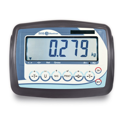
Baxtran BR15 User manual

1
enUSER’S MANUAL BR15
V.1.2
en
InDICATOR
BR 15
marca propiedad de | est une marque de | trade mark propiety of:
Pol. Empordà Internacional Calle F. Parcela 15-16
17469 VILAMALLA - (Girona) SPAIN T.
(34) 972 527 212 - F. (34) 972 527 211
El fabricante se reserva el derecho de modificar sin previo aviso las características de sus productos para introducir mejoras técnicas o cumplir con nuevas regulaciones oficiales./Le
constructeur se réserve le droit de modifier les caractéristiques de ses produits en vue d’y apporter des améliorations techniques ou de respecter de nouvelles réglamentations./The
manufacturer reserves the right to modify the specifications of its products in order to make technical improvements or comply with new regulations.
16/12/2014


BR15
3
en
1. eXCITATIOn 4
2. BeFORe ITS USe 4
3. COnSUMPTIOn 4
4. LOAD CeLL COnneCTIOn TO THe InDICATOR 4
5. KeYBOARD DeSCRIPTIOn 5
6. BR15 APPLICATIOnS 6
6.1 NORMAL WEIGHING MODE 6
6.1.1 EQUIPMENT CONFIGURATION 6
6.1.2 FIRST CALIBRATION 6
6.1.3 USE 6
6.2 MODE COMPTEUSE 6
6.2.1 EQUIPMENT CONFIGURATION 6
6.2.2 FIRST CALIBRATION 6
6.2.3 USE 6
6.3 LIMITS AND ALARM 6
6.4 UNIT RANGE/ MULTI RANGE/ MULTI INTERVAL 7
7. PARAMeTeRS 7
8. PARAMeTeRS COnFIGURATIOn 7
8.1 INTERNAL COUNTING (A/D) 7
8.2 CONFIGURATION OF THE WEIGHT LIMITS (SUPERIOR AND INFERIOR) 8
8.3 AUTO SWITCH OFF 8
8.4 CONFIGURATION OF THE ILLUMINATION OF THE DISPLAY 8
8.5 HOLD FUNCTION 9
8.6 RS-232 DATA EXIT 9
8.7 CONFIGURATION OF THE SPEED OF THE AD CONVERTER 12
8.8 BLIND 12
8.9 CONFIGURATION OF THE GRAVITY 12
8.10 SPEED OF THE FILTER 12
8.11 SPEED OF STABILITY 12
9. COnFIGURATIOn OF THe ReADJUSTMenTS In CALIBRATIOn 13
10. TeCHnICAL PARAMeTeRS 13
11. GUARAnTee 18
DECLARATION OF CONFORMITY 19
InDeX

enUSER’S MANUAL BR15
4
1. eXCITATIOn
BR15
Input 230~240V
Output 10V 600mA
Rechargeable Battery 6V/4Ah
2. BeFORe ITS USe
1. Use an independent electric source to prevent electronic disturbances.
2. Don’t place any object on the platform when switching on the indicator.
3. Please, warm-up the scale during 2-3 minutes before using it.
4. Avoid sudden changes in temperature and draughts.
5. Don’t overload the scale; do not exceed its maximum capacity.
3. COnSUMPTIOn
BR15
Battery life: without back illumination, approx, 160 hours.
With back illumination, approx, 120 hours.
4. LOAD CeLL COnneCTIOn TO THe InDICATOR
The connector of the load cell has 5 pins
Do not disconnect the connector of the load cell when the indicator is working, because you could damage the equipment.•
BROCHE 1 EXC +
BROCHE 2 EXC -
BROCHE 3 SIG +
BROCHE 4 SIG -
BROCHE 5 GND
MALE
LOAD CELL
CABLE
LOAD CELL
EXC +
EXC -
SIG -SIG +

5
enUSER’S MANUAL BR15
5. KeYBOARD DeSCRIPTIOn
First function;Press this key to switch on the scale.
Second function;to place the reading of the display at “0”, the value of the display must be lower to + 2% of
the maximum capacity.
Third function;to move to the right in the programming mode.
First function; : press and hold the key during 3 seconds to switch of the indicator.
First function;to choose the unit of weight.
Second function;to exit from the programming mode.
First fonction;: to remove (tare) the weight of a container.
Second fonction;to move to the left.
First fonction;to view the number of accumulations and the accumulated weight.(TOTALIZING)
Second fonction;To remove the memory of the accumulations.
Third fonction;To increase the values inside the programming.
First fonction;To accumulate in memory the value of the weight that appears in the screen.
Second fonction;manual transmission of data through RS-232 port to a PC or printer.
Third fonction;confirmation key in the programming mode.

enUSER’S MANUAL BR15
6
6. BR15 APPLICATIOnS
6.1 NORMAL WEIGHING MODE
6.1.1 EQUIPMENT CONFIGURATION
6.1.2 FIRST CALIBRATION
6.1.3 USE
6.2 MODE COMPTEUSE
6.2.1 EQUIPMENT CONFIGURATION
6.2.2 FIRST CALIBRATION
6.2.3 USE
6.3 LIMITS AND ALARM
6.4 UNIT RANGE/ MULTI RANGE/ MULTI INTERVAL
6.1 NORMAL WEIGHING MODE
6.1.1 CONFIGURATION OF THE EQUIPMENT
See section LF2 of the technical parameters
6.1.2 FIRST CALIBRATION
See section LF1 of the technical parameters
6.1.3 USE
Switch on the equipment when all the parameters have been correctly configured and the equipment has been calibrated
Make sure than the value of the indicator, without load on the platform, is 0. If this is not the case, press•
Place the weight on the platform and the platform will show the weight.•
The accumulation and sending of data will depend on the mode chosen in the section• UF-6
You can display the accumulated values at any time by pressing• (TOTALIZING)
6.2 PIECE COUNTING MODE
6.2.1 CONFIGURATION OF THE EQUIPMENT
See section LF2 of the technical parameters
6.2.2 FIRST CALIBRATION
See section LF1 of the technical parameters
6.2.3 USE
Switch on the equipment when all the parameters have been correctly configured. Make sure that the value on the visor, with no load on the
platform, is 0. If this is not the case press the key .
STEPS TO FOLLOW;
Press the key1. until the symbol PCS appears on the screen
Press the key2. successively to choose the quantity of pieces of the sample. On the screen will appear, successively, C10/C20/C50/
C100/C200.
Place the sample on the platform, and wait until the sign of stability and press the key3. .
Place the product on the platform and the screen will show the number of pieces4. .
The accumulation and the sending of data will depend on the mode chosen in the section UF-6.
To turn to the normal weighing mode, press the key•
If the user wants to go back to the piece counting mode, using the same sample of reference, press the key• again.
If the user want to change the sample of reference, the user must repeat the steps described above.•
6.3 LIMITS AND ALARM
The user can configure the superior and inferior limits of the sample placed on the platform.
The display will show if the sample is lower to the inferior limit Lo, above the superior limit Hi or in the zone between the two limits OK
The user can configure when he wants to make the alarm ring and the stability needed to make it happen.
All the procedure is described in the section UF-2.
If the user wants to define the limits in the normal weighing mode and wants to use the limits in piece counting mode, he must define the new
limits for this mode, when it changes to weight mode again, the user will recover the limits he already has. The same happens otherwise.

7
enUSER’S MANUAL BR15
6.4 UNIT RANGE / MULTI-RANGE / MULTI-INTERVAL
The indicator can be configured with an only range, a maximum weight and a value of step. It can also be configured as multi range or multi interval,
in such cases there is a maximum weight.
From 0 to the medium weight of these maximum weight it is used the value of the chosen step ( step 1) and from the half to the maximum weight
it is used the next value in the step ( step 2).
The screen indicators R1 and R2 point out the range which the user is using at every moment.
In the multi interval mode the weight increases, in the range use it used step 1, when the user goes to range 2 the step 2 is used.
When the weight decreases and the user go back to range 1, the step 1 is used again. On the contrary, in mode multi range, when the weight
decreases and the device go back to range 1, the device continues using step 2 until it reaches 0.
In the section LF2 of the technical parameters the user can choose the range mode.
7. PARAMeTeRS
PARAMETER DESCRIPTION
UF-1 Internal calculation (A/D)
UF-2 Limit Configuration of weight ( superior and inferior)
UF-3 auto auto off
UF-4 Back illumination of display
UF-5 Four modes of hold
UF-6 RS-232 Output ( PC/PRINT)
UF-7 Configuration of the speed of the converter (A/D)
UF-8 blind
UF-9 Configuration of gravity
UF-10 Speed of filter
UF-11 Stabilizing stability
8. PARAMETERS COnFIGURATIOn
8.1 INTERNAL COUNTING (A/D)
8.2 CONFIGURATION OF THE WEIGHT LIMITS (SUPERIOR AND INFERIOR)
8.3 AUTO SWITCH OFF
8.4 CONFIGURATION OF THE ILLUMINATION OF THE DISPLAY
8.5 HOLD FUNCTION
8.6 RS-232 DATA EXIT
8.7 CONFIGURATION OF THE SPEED OF THE AD CONVERTER
8.8 BLIND
8.9 CONFIGURATION OF THE GRAVITY
8.10 SPEED OF THE FILTER
8.11 SPEED OF STABILITY
To access the configuration of parameters when the screen is in zero, the user must press at the same time the keys and .
Press the key or to choose the desired character (UF-1 ~ UF-11).
To go back to the previous mode press the key .
8.1 INTERNAL COUNTING (A/D) | UF-1
1. Press the key to view the internal sums of the scale.
2. To go to the next parameter, press the key the screen will show the value of the voltage of the battery.
3. To exit this mode and go back to the normal weighing, the user must press the key or

enUSER’S MANUAL BR15
8
8.2 CONFIGURATION OF THE LIMITS OF WEIGHT ( SUPERIOR AND INGERIOR) | UF-2
1. Press the key to access the parameter.
2. The display will show the message “ 000.00L” ( inferior limit)
3. Use the keys and to move the cursor and the key to choose the desired number..
4. Press the key to confirm.
5. The display will show the message “000.00h” (Superior limit=Hi)
6. Use the keys and to move the cursor and the key to choose the desired number.
Note: If you need to change or modify the last digit you can place the cursor on it to do it.
7. Press the key to confirm.
8. The display will show the value.
A B C
0 0 0
(configuration of the alarm)
DISPLAY VALUE ESTABILITY
A 0 There is no need to stabilize the alarm to make it ring
1 The alarm must be stabilized to ring
B 0 Always 0
C 0 Alarm switched off
1 The alarm ring if it is place on the band OK
( between the limits Lo and Hi)LO OK HI
2 The alarm rings if it is situated below the
inferior limit Lo or above the superior limit
Hi
LO OK HI
9. Press the keys and to move the cursor and the key to choose the desired number..
10. Press the key to confirm.
8.3 AUTO SWITCH OFF| UF-3
MODES:
AoFF 00• – Auto switch off deactivated
AoFF 01• – Auto switch off activated in a minute. The scale is going to switch off automatically after 1 minute of not being used.
You can configure the value wished from 1 to 99 minutes.•
1. Press the key to have an access to the parameter.
2. Press the keys and to move the cursor and the key to choose the desired number.
3. Press the key to confirm.
8.4 DISPLAY BACKLIGHTING | UF-4
MODES:
A:• Automatic.
ON• : Illumination Activated.
OFF• : Illumination Deactivated.
1. Press the key to have an access to the parameter.
2. Press the key to select the desired mode.
3. Press the key to confirm.

9
enUSER’S MANUAL BR15
8.5 HOLD FUNCTION | UF-5
(Once the object is retired from the plate, the display maintains the weight fixed during some seconds. This function is very useful for the weighing of
animals)
1. Press the key to access to the parameter.
2. Press the key to choose the desired mode.
3. Press the key to confirm.
MODES:
HOLD 0• : Deactivated.
HOLD 1• : Animal in movement
HOLD 2• : Value of peak
HOLD 3• : Hold steady
HOLD 4• : Hold steady with self cancelling at zero.
HOLD 1.
When the user can access this parameter, the screen shows the message
• PCt,
Use the keys
• and to move the cursor and the key to choose the desired value of the range of HOLD, you can choose a
number from 001 to 100.
Press the key
• to confirm.
It will appear on the screen the message
• time 8, use the keys and to move the cursor and the key To choose the
number of times you want to repeat during the range of hold.
Press the key
• to confirm. Example: PCt small and big time means more accuracy and longer stabilization.
8.6 RS-232 DATA EXIT|UF-6
232 0 EXIT RS-232 DEACTIVATED
FORMAT OF THE DATA
Format 1 PC
VARIOUS FORMATS AVAILABLE
CONNECTION SENDING 232 1
232 2
232 3
Connection sending, without accumulation, when it achieves an estability with format 1
Continuous connection sending with format 1
Connection sending, without accumulation, manual by pressing the key with format 1
Formato 2 PC
VARIOUS FORMATS AVAILABLE
CONNECTION SENDING 232 4
232 5
232 6
Connection sending, without accumulation, when it achieves the stability with formato 2
Continuous connection sending with formato 2
Connection sending, without accumulation, manual by pressing the key with format 2

enUSER’S MANUAL BR15
10
Format 3 printer
DIFFERENT POSSIBLE FORMATS
232 7 232 8
Connection sending and manual accumulation, passing by zero and
pressing the key with format 3.
Connection sending and automatic accumulation to stability, passing
0 with format 3.
If the user presses the key twice one after the other when the
screen is in 0, the total line is printed.
If the user presses the key twice one after the other when the
screen is in 0, the total line is printed
And the memory of the weights is removed And the memory of the weights is removed
Format 4 printer
DIFFERENT POSSIBLE FORMATS
232 9 232 10
Connection sending and manual
accumulation, passing 0 and
pressing the key with
format 4.
Connection sending and automatic
accumulation to stability, passing
0 and pressing the key
with format 4.
If the user presses the key
twice one after the other when the
screen is in 0, the summarizing of
the tickets is printed
If the user presses the key
twice one after the other when the
screen is in 0, the summarizing
of the tickets is printed. And the
memory of weights is removed
And the memory of weights is removed And the memory of weights is removed

11
enUSER’S MANUAL BR15
8.6.1 SPEED OF TRANSMISSION
1. Press the key to access the parameter
2. Press the key to choose the data exit mode wanted.
3. Press the key to confirm.
SPEED OF TRANSMISSIOIN
b1200 1200 baud
b2400 2400 baud
b4800 4800 baud
b9600 9600 baud
b19200 19200 baud
b38400 38400 baud
4. Press the key to choose the speed of transmission needed.
5. Press the key to confirm.
8.6.2 PROTOCOL OF COMMUNICATION
UART SIGNAL OF EIA-RS232 C
Exit serie 1200 / 2400 / 4800 / 9600 / 19200 / 34800 bps
Bits of data 8 bits
Bits of parity No
Bits of stop 1 bit
HEADBOARDS INFORMATION
Headboard 1 (2 BYTES) Headboard 2 (2 BYTES)
OL – overweight
ST – steady NT – Net weight
US – UNSTEADY GS – Gross weight
FORMAT 1 (232 1 ~ 3):
18 BYTES ASCII FOR THE UNITIES kg, g, t, lb
12, 12, 1234567812CRLF
Headboard 1 Headboard 2 data Unit
21 BYTES ASCII FOR THE UNITIES tl, T, lboz
12, 12, 1234567891234CRLF
Headboard 1 Headboard 2 data Unit
19 BYTES ASCII FOR THE UNIT pcs
12,12,12345678123CRLF
Headboard 1 Headboard 2 data Unit

enUSER’S MANUAL BR15
12
FORMAT 2 (232 4 ~ 6):
12 BYTES ASCII FOR THE UNITIES kg, g, t, lb
1234567812CRLF
data Unit
15 BYTES ASCII FOR THE UNITIES tl, T, lboz
1234567891234CRLF
data Unit
13 BYTES ASCII FOR THE UNIT pcs
12345678123CRLF
data Unit
8.7 CONFIGURATION OF THE SPEED OF THE CONVERTER |UF-7
1. Press the key to access the parameter.
2. Press the key to choose the desired mode:
Mode 1 : Normal•
Mode 2: Fast•
Mode 3: Slow•
3. Press the key to confirm.
8.8 BLIND|UF-8
It appears 0 on screen until the next division is selected. It starts to show values from that division.
Example:
Scale with e =2g
Blind in 5 divisions
It will show 0 until it reaches 25= 10 g, the first value it will show will be 12g.
1. Press the key to access the parameter.
2. Press the key to select.
3. Press the key to confirm..
8.9 CONFIGURATION OF GRAVITY|UF-9
1. Press the key to view the value of the actual gravity.
2. To change the value, press the key , next you must use the key and to move the cursor and the key to
select the desired number.
3. Press the key to confirm.
8.10 SPEED OF THE FILTER|UF-10
1. Press the key to view the value of the actual filter.
2. Press the key to choose the desired value between 1/2/3/4, the biggest is the number the most stability.
8.11 SPEED OF STABILITY|UF-11
1. Press the key to view the value of the actual filter.
2. Press the key to choose the desired value between 1/2/3/4, the biggest is the number the most stability.

13
enUSER’S MANUAL BR15
9. COnFIGURATIOn OF THe ReADJUSTMenTS In CALIBRATIOn
1. When the user is in the normal mode of weighing, he must press the keys and , the message ECF-1 is going to appear
on the display.
2. Press the keys or to select the desired function: ECF-1, ECF-2 or ECF-3
* ECF-1 CALIBRATION OF ZERO + WEIGHT
Press the key ,the display will show CALZ.
Press the key ,to put the reading of the display to zero.
Press the keys and to move the cursor.
Press the key to introduce the value of the weight of calibration.
Place the weight of calibration on the platform and press the key to do the calibration once the reading is
steady.
* ECF-2 CALIBRATION OF ZERO
Press the key , the display will show CALZ.
Press the key , to put the reading of the display to zero.
Press the key , to calibration.
* CALIBRATION OF WEIGHT (SPAN)
Press the key , the display will show the value of the weight of calibration.
Press the keys and to move the cursor.
Pulsar la tecla to modify the value of the weight of calibration.
Pulsar la tecla to confirm.
Place the weight of calibration on the platform and press the key to do the calibration once the reading is
stable.
10. TeCHnICAL PARAMeTeRS
DO NOT MODIFY THE TECHNICAL PARAMETERS IF IT IS NOT STRICTLY NEEDED. A BAD CONFIGURATION OF THIS SECTION
CAN CAUSE A WRONG FUNCTIONING OF THE SCALE.
ENTRANCE AND EXIT OF THE CALIBRATION
DISPLAY DESCRIPTION AND SEQUENCE OF USE
With the visor switched off, press and hold the key until the message P000, appears on the
screen, then you can release the key .
, and introduce the code 0020.
to start or the key to exit the menu and the indicator will begin again
automatically.
LF 1

enUSER’S MANUAL BR15
14
CALIBRATION OF THE WEIGHT LF 1
DISPLAY DESCRIPTION AND SEQUENCE OF USE
The calibration can be done with any weight, but the weight ca not be inferior to 1/100 of the maxi-
mum capacity and it must also never be exceeded.
Press the key to start the calibration of zero ( press To exit the calibration and go back to
the menu LF1)
LF 1
CAL Z
150.00 kg se , and , 0 ~ 9 and then press to introduce the weight with which the
calibration will be done. ( press the key to exit the calibration and go back to the menu LF1)
150.00 kg lace the required weight on the scale as it is indicated in the display.
150.00 kg to calibrate it ( press the key ESC to exit the calibration
and go back to the menu LF1).
THE CALIBRATION IS GOING TO FINISH AND THE SCALE WILL GO VACK TO THE WEIGHING MODE AUTOMATICALLY.
CONFIGURATION LF 2
DISPLAY DESCRIPTION AND SEQUENCE OF USE
FIRST STEP
262144
SECOND STEP
A: Metric system 0:NO 1: kg 2:T 3:g
100001
B: American system 0:NO 1: lb 2:lb oz
C: other unities 0:NO 1: TW kg 2:HK kg 3:VISS
D: PCS 0:OFF 1: ON
A B C D E F E: double range 0:OFF 1: multi interval 2:multi range
F: units of calibration 1:use metric
unities 2:use american unities
lb oz cannot be selected as unities of calibration.
The scale won’t let us continue up to the next step if there is a mistake during the programming.
THIRD STEP
Use , and , 0 ~ 9 and then press to introduce THE MAXIMUM CAPACITY.
000000kg
FOURTH STEP
Use the Keys , to change the position of the DECIMAL POINT.
dP 0.0
d 0.00 d 0.000 d 0.0000 0.00000
FIFTH STEP se to select the DIVISION:
diV 01, diV 02, diV 05, diV10, diV 20, diV 50
diV 01
After introducing the parameters LF2, the indicator will show the last configuration saved. All the
steps to follow must be completed, if they are not done the indicator will continue with the previous
configuration.
Proceed with the calibration of weight after LF2.

15
enUSER’S MANUAL BR15
LF 2 Press the key to start and display the internal value. Press to exit the menu and the scale
will automatically restart.
262144 Press the key To continue with the configuration. (press the key to exit from the configu-
ration and go back to the menu LF2).
100001 se the keys , and , 0 ~ 9 and then press the key to choose the UNITS
OF WEIGHT . (press the key to exit from the configuration and go back to the menu LF2).
000000kg se the keys , and , 0 ~ 9 and then press the key to choose the MAXI-
MUM WEIGHT. press the key to exit from the configuration and go back to the menu LF2).
d 0.0kg se the keys , and Then To move the decimal point ( press the key To exit
from the configuration and go back to the menu LF2).
div 01 Use and then to change the step. (Press the key To exit from the configuration and
go back to the menu LF2).
LF2 Use , and then To continue with the other configuration or press the key to
exit from the menu and the scale will begin again automatically).
LINEAL CALIBRATION LF 3
Up to six steps of calibration W0 ~W6
Make sure that the plate of the scale is empty before starting the calibration.
Press the key for the first point of calibration.
The previous points of calibration will be removed and the message CLEAR is going to appear on the screen.
Press the key to proceed with the next point of calibration.
Press the key to go back to the previous point of calibration.
Press the key to keep everything.
Press the key to finish the calibration and go back to the menu LF3.
DISPLAY DESCRIPTION AND SEQUENCE OF USE
LF3 Press the Key to start or the key To exit the menu and the scale will start again automa-
tically
W0 Press the Key to calibrate the zero.
( press the key to exit from the calibration and go back to the menu LF3)

enUSER’S MANUAL BR15
16
W1 lace 1/3 of the maximum weight on the plate and press to calibrate 2/3 th the capacity. (press
the key to exit from the calibration and go back to the menu LF3)
W2 lace 2/3 of the maximum weight on the plate and press to calibrate 2/3 th the capacity. (press
the key to exit from the calibration and go back to the menu LF3)
W3 lace the maximum weight on the plate and press the key to calibrate the full capacity. (press
the key to exit from the calibration and go back to the menu LF3)
W4 ress the key to complete the lineal calibration. (press the key to exit from the calibration
and go back to the menu LF3)
LF3 se the keys , and then the key to continue with other adjustments and press the
key to exit from the menu and the scale will begin again automatically.
SPEED OF THE AD CONVERTER LF 4
SPEED 1 standard speed 15Hz.
SPEED 2 high speed 30Hz.
SPEED 3 low speed 7.5Hz
*This function stays blocked when UF-5 is in mode HOLD 1.
*The value of factory is 1
DISPLAY DESCRIPTION AND SEQUENCE OF USE
LF4 ress the key to start or the key to exit from the menu and the scale is going to begin
again automatically.
SPEED 1 se the key and then the key to select the speed of the AD converter ( press the key
to exit from the configuration and go back to the menu LF4)
LF 4 se the keys , and then To continue with the other adjustment and press the key
to exit from the menu and the scale will start again automatically.

17
enUSER’S MANUAL BR15
BLINF LF 5
DISPLAY DESCRIPTION AND SEQUENCE OF USE
ZP 0 OFF
ZP 1 One division will not show being at zero
ZP 2 Two division will not show being at zero
ZP 3 Three divisions will not show being at zero
ZP 4 Four divisions will not show being at zero
ZP 5 Five divisions will not show being at zero
*This function is going to be blocked when UF-5 is in mode HOLD 1
*The value of factory is ZP 0
LF 5
DISPLAY DESCRIPTION AND SEQUENCE OF USE
to start or the key to exit from the menu and the scale will start again
automatically.
LF 5
ZP 0 se the key and the key to select how many divisions will show when in zero ( press
ESC to exit from the configuration and go back to the menu LF4)
LF 5 se the keys , and then the key to continue with other adjustment or press the key
to exit from the menu and the scale is going to start automatically.
APPROVAL CONFIRMITY LF 6
DISPLAY DESCRIPTION AND SEQUENCE OF USE
nonE Version not approved
DON’T MODIFY, IN NO WAY, THIS PARAMETER. IT MUST ALWAYS BE CONFIGURED AT
nonE.
The change of this parameter implies the blocking of some functionalities.
LF 6
!
GRAVITY LF 7
*Introduce the gravity of your zone before doing the first calibration.
*Introduce the gravity of destination after doing the calibration.
*The value of the gravity will be denied if it is bigger than 9.83217 ( gravity of the pole) or inferior to 9.78031 ( gravity of the
equator).
Value of factory: 9.8035
DISPLAY DESCRIPTION AND SEQUENCE OF USE
Press the key to continue or the key to exit from the menu and the scale will start again
automatically.
LF 7
-00- The screen is going to show the number of pre-calibration during one second.

enUSER’S MANUAL BR15
18
9.8035 Press the key to continue.
9.8035 se the keys , and , 0 ~ 9 and then the key to introduce the value of
gravity ( press ESC to exit from the configuration and go back to the menu LF7)
INITIAL ZERO LF 8
SEtZ Y resets of the point of zero every time that the scale is begun again.
SEtZ n resets of the point zero OFF
DISPLAY DESCRIPTION AND SEQUENCE OF USE
ress the key to start or the key to exit from the menu and the scale will start again
automatically.LF 8
se the key and then the key to choose the mode of zero initial ( press the key …to exit
from the configuration and go back to the menu LF8)SetZ Y
LF 8 Use the keys , and then the key to continue with other adjustments o press the key
to exit from the menu and the scale will start again automatically.
11. GUARAnTee
This scale has a warranty against all manufacture and material defects, for a period of a year starting with the delivery date.
During this period, GIROPES, will be in charge of the repairing of the scale.
This warranty does not include the damages done by overload or wrong use.
The warranty does not cover the delivery expenses necessary for the repair of the scale.
BR15
DECLARACIÓN DE CONFORMIDAD | DECLARATION OF CONFORMITY | DÉCLARATION DE CONFORMITÉ | KONFORMITÄTSERKLÄRUNG
DECLARACIÓN DE CONFORMIDAD
DECLARATION OF CONFORMITY
DÉCLARATION DE CONFORMITÉ
KONFORMITÄTSERKLÄRUNG
Nosotros:
We/ Nous/ Wir:
BAXTRAN S.L.

Pol. Empordà International
C/F. Parcela 15-16
E-17469 VILAMALLA (Girona)
- SPAIN -
Declaramos bajo nuestra responsabilidad que el producto denominado:
Declare under our responsibility that the denominated product:
Nous déclarons sous notre résponsabilité que le produit ci-dessous nommé:
Erklären unter unserer Verantwortung, dass das Produkt mit dem Namen:
Indicador BR15
Indicator BR15
Indicateur BR15
Auswertegeräte BR15
A la cual se refiere la presente declaración, es conforme a las siguientes normas o documentos:
To wich déclaration referes to, conform wich the followings standards or other normative documents:
A la quelle se refaire la présente déclaration, et conforme aux normes suivantes ou documents:
auf das sich diese Erklärung bezieht, mit den nachstehenden Normen und folgende Standards übereinstimmt:
Conformidad CE:
CE conformity / conformité CE / CE Kennzeichnung:
2004/108/CE Directiva sobre la compatibilidad electromagnética.
2004/108/CE directive on the electromagnetic compatibility.
2004/108/CE directive surla compatibilité electromagnétique.
2004/108/CE Richtlinie über Die Elektromagnetische Verträglichkeit .
2006/95/CE Directiva sobre baja tensión.
2006/95/CE low tension directive
2006/95/CE directive sur les baisses tensions.
2006/95/CE Richtlinie Spannung Sinkt.
Jordi Ribalta
Director General
General Manager

enUSER’S MANUAL BR15
20
marca propiedad de | est une marque de | trade mark propiety of:
Pol. Empordà Internacional Calle F. Parcela 15-16
17469 VILAMALLA - (Girona) SPAIN T.
(34) 972 527 212 - F. (34) 972 527 211
Table of contents
Other Baxtran Measuring Instrument manuals