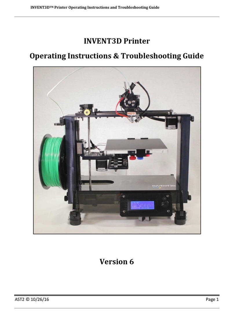
AST2 INVENT3D Installation instructions

INVENT3DPrinterKitDisassemblyInstructions
AST2©10/26/161
INVENT3DPrinterKit
DisassemblyInstructions
Version6

INVENT3DPrinterKitDisassemblyInstructions
AST2©10/26/162
I.GeneralDisassemblyInstructions
Usethecaselayerdrawingstoensurethatcomponentsarestoredintheappropriate
location
UsetheappropriatesizeAllenwrenchtoloosenthumbscrewsthataretootightto
loosenbyhand
Unless otherwise noted, printer kit components and subassemblies are not to be
disassembled;disassemblyshouldreturntheprinterkittothesameconditioninwhich
itarrived.
Screwsthatareblackanodizedshouldnotberemoved.
II.CaseLayerDrawings
ThefollowingCaseLayerDrawingsdepictthelayoutandcontentsofeachlayerofcomponents
withintheINVENT3Dprintercase.Thesedrawingsarelabeledfromthetopdownwithinthe
case,meaningLayer1isthetoplayerandLayer4isthebottomlayer.Pleasereviewthese
drawingspriortodisassemblyandreferencethesedrawingsthroughoutthedisassembly
processtoensurethatallcomponentsarestoredintheappropriatelocations.

INVENT3DPrinterKitDisassemblyInstructions
AST2©10/26/163

INVENT3DPrinterKitDisassemblyInstructions
AST2©10/26/164

INVENT3DPrinterKitDisassemblyInstructions
AST2©10/26/165
III.DetailedDisassemblyInstructions
1. Backoutfilament.Refertoprocessforloadingandunloadingfilamentdescribedinthe
INVENT3DOperatingInstructions.
2. PlacethefilamenttubeandUSBcableintolocationasshowninCaseLayerDrawing3.
3. RemovepowersupplyandstoreinappropriatelocationasshowninCaseLayerDrawing
3.Thedetachablecordcanbestoredwhenthesecondlayerisplacedontop.

INVENT3DPrinterKitDisassemblyInstructions
AST2©10/26/166
4. Removesidecoversandeightblackthumbscrewsandsetaside.Storefilamentguidein
locationasshowninCaseLayerDrawing3.
5. Removewhitethumbscrewsandspoolholderfromleftsidecover.Storespoolholderin
locationasshowninCaseLayerDrawing1.Placewhitethumbscrewsinz-axisand
framecomponentsboxasshowninCaseLayerDrawing1.
6. RemovetopcoverandstoreinlocationasshowninCaseLayerDrawing4.

INVENT3DPrinterKitDisassemblyInstructions
AST2©10/26/167
7. Removeallzipties.Useneedlenoseplierstoassistinremovingziptiesbyplacing
pressureonthelatchlightlywiththepliers.Straightenthelatchifbentafterremoving.
Storeziptiesinz-axisandframecomponentsboxasshowninCaseLayerDrawing1.
8. Removewiresleeves.PlacewiresleevesinlocationasshowninCaseLayerDrawing3.
9. Removeprintboard.StoreprintboardinlocationasshowninCaseLayerDrawing4.

INVENT3DPrinterKitDisassemblyInstructions
AST2©10/26/168
10. CarefullyremoveallwiringfromRAMBoboardexceptforfanwiring.Besuretodepress
latchesforplugsthathavelatches–theplugsshouldbeeasytoremovewithlatches
depressed.
11. Removerearcover.Detachpowerplugbreakoutboardfromrearcoverbyremovingset
screw.Reattachsetscrewtopowerplugbreakoutboardclip.Storerearcoverin
locationasshowninCaseLayerDrawing4.Storepowerplugbreakoutboardinlocation
asshowninCaseLayerDrawing3.
12. Removeblackmini-thumbscrewandHOT!sign.StoretheHOT!signinplasticboxfor
hotendcomponentsasshowninCaseLayerDrawing3.Storetheblackmini-
thumbscrewintheplasticboxforx-axiscomponentsasshowninCaseLayerDrawing1.
13. Disconnectfanwiresfromhotend.Removeallwiresfromcircularcutoutsinleftand
rightframes.RememberthatthefanwiresstayattachedtotheRAMBoboard.

INVENT3DPrinterKitDisassemblyInstructions
AST2©10/26/169
14. RemovefrontcoverwithLCDscreen.RemovetheLCDscreenfromthefrontcover.
StoretheLCDscreeninthelocationasshowninCaseLayerDrawing2.Placethefront
coverinthelocationasshowninCaseLayerDrawing4.
15. RemoveorangethumbscrewsandRAMBoboardfrombottomframeplate.Placethe
RAMBoboardinthelocationasshowninCaseLayerDrawing1withfanwiringcoiled.
Storetheorangethumbscrewsintheplasticcaseforz-axisandframecomponentsas
showninCaseLayerDrawing1.

INVENT3DPrinterKitDisassemblyInstructions
AST2©10/26/1610
16. Removesilverthumbscrewsandextrudertop.Storetheextrudertopinthelocationas
showninCaseLayerDrawing1.Placethesilverthumbscrewsintheplasticboxforx-
axiscomponentsshowninCaseLayerDrawing1.
17. Removetheextrudermotorfromitsseatingontheextruderbottom.Removethe
filamentdrivefromtheextrudermotorandreplacethefilamentdrivemounting
hardwareintheextrudermotor.Coiltheextrudermotorwirearoundthebaseofthe
motorandstoreinthelocationasshowninCaseLayerDrawing3.Storefilamentdrive
inlocationasshowninCaseLayerDrawing1.

INVENT3DPrinterKitDisassemblyInstructions
AST2©10/26/1611
18. Carefullyslidehotendalongitsslotontheextruderbottomtoremove.Onlyapply
pressuretotheupperportionofthehotend.Coilwiresanduseadetachableziptie
toholdinplace.Storethehotendinplasticboxforhotendcomponentsasshownin
CaseLayerDrawing3.StorehotendcomponentboxinlocationshowninCaseLayer
Drawing1.

INVENT3DPrinterKitDisassemblyInstructions
AST2©10/26/1612
19. Removetheextruderbottom.Re-insertextruderbottommountinghardwareintothe
samelocationstheywereremovedonthex-axisrailcarriageandx-axisbeltclamp;
longerscrewsshouldbeinsertedintothebeltclamp.Removex-axislimitswitchfrom
extruderbottomandre-insertthescrewsintothelimitswitchwithnutsonends.Coil
limitswitchwireandplaceinplasticboxforx-axiscomponentsasshowninCaseLayer
Drawing1.StoreextruderbottominlocationasshowninCaseLayerDrawing1;the
extruderbottomshouldbeplacedbelowtheextrudertopandfilamentdrive.

INVENT3DPrinterKitDisassemblyInstructions
AST2©10/26/1613
20. Removeidlerboltfromtopframeplateandre-attachnuttoend.Removex-axisbelt.
Removez-axislimitswitchendstopwithspring.Removeyellowthumbscrewfromz-
axislock.Placetheidlerbolt,x-axisbelt,z-axislimitswitchendstopwithspring,and
yellowthumbscrewintotheplasticcaseforx-axiscomponentsshowninCaseLayer
Drawing1.Storex-axiscomponentboxinlocationshowninCaseLayerDrawing1.

INVENT3DPrinterKitDisassemblyInstructions
AST2©10/26/1614
21. Removex-axismotorandre-insertmountinghardwareintothetopofthemotorwith
thesmallestscrewinthefrontleftcorner.Coilwirearoundbaseofmotor.Storethex-
axismotorinthelocationasshowninCaseLayerDrawing3.
22. Removeleadscrewknobbylooseningsetscrewandsetaside.Removetopframeplate,
liftingthebearingfromtheleadscrewatthesametime.Storeflatheadscrewsand
bearinginplasticcaseforz-axisandframecomponentsasshowninCaseLayerDrawing
1.PlacetopframeplateinlocationasshowninCaseLayerDrawing2.

INVENT3DPrinterKitDisassemblyInstructions
AST2©10/26/1615
23. Removebluethumbscrewandfrontclampfromfrontofprintboardplate.Removered
thumbscrewsthatattachprintboardplatetodiamondplateandremoveprintboard
plate.Removerearclampsfromprintboardplate,andreinsertmountinghardwareinto
theprintboardplate.Removeprintboardspacerandsprings.Placespringsonred
thumbscrewsandreinsertintoprintboardplate.Placefrontandrearboardclamps,
printboardspacer,andbluethumbscrewintotheplasticcasefory-axiscomponentsas
showninCaseLayerDrawing1.PlaceprintboardplateinlocationasshowninCase
LayerDrawing3underneathothercomponentsinthislocation.

INVENT3DPrinterKitDisassemblyInstructions
AST2©10/26/1616
24. Removediamondplate.Re-insertmountinghardwareintothey-axiscarriageandy-axis
beltclampinthelocationsfromwhichtheywereremoved.Storediamondplatein
plasticboxfory-axiscomponentsasshowninCaseLayerDrawing1.
25. Removefrontidlerboltlocatedinslottedholeony-axisplateandreplacenutonend.
Removey-axisbelt.Storeidlerboldandy-axisbeltinplasticcasefory-axiscomponents
asshowninCaseLayerDrawing1.

INVENT3DPrinterKitDisassemblyInstructions
AST2©10/26/1617
26. Removey-axisplatebyremovingthreeflatheadscrews.Removeremainingidlerbolts
andreplacenutsonends.Coily-axislimitswitchwireandpassplugendthroughthe
coilsothatitdoesn’tbecomeunraveled.Storeidlerboltsandflatheadscrewsinplastic
casefory-axiscomponentsasshowninCaseLayerDrawing1.Placey-axiscomponents
plasticboxinlocationasshowninCaseLayerDrawing1.Placey-axisplateinlocationas
showninCaseLayerDrawing3.

INVENT3DPrinterKitDisassemblyInstructions
AST2©10/26/1618
27. Removey-axismotorandreinsertmountinghardwareintothetopofthemotor.Coil
wirearoundbaseofmotorandpassplugendunderthecoiltopreventfromunraveling.
Storey-axismotorinlocationasshowninCaseLayerDrawing3.
28. RemovefourflatheadscrewsthatattachL-platetothez-axiscarriage.Rotatelead
screwtoremoveL-plate.Replaceflatheadscrewsinz-axiscarriage.Coilz-axislimit
switchwireandplaceplugendthroughcoiltoholdinplace.StoreL-plateinlocationas
showninCaseLayerDrawing2.

INVENT3DPrinterKitDisassemblyInstructions
AST2©10/26/1619
29. Removegoldthumbscrewsthatconnectz-axismotortobottomframeplateand
removez-axismotormount.Removez-axismotor.Placez-axismotormounton
bottomofz-axismotorandinsertandtightengoldthumbscrews.Placeleadscrewknob
ontopofleadscrewandlightlytightensetscrew.Storethez-axismotorinlocationas
showninCaseLayerDrawing3.
30. Removegreenthumbscrewsthatattachprinterlegstoleftandrightsideframesand
removeprinterlegs.Removeprinterfeetfromprinterlegsandreplaceprinterfoot
mountinghardwarebackintotheprinterfeet.Storegreenthumbscrewsinplasticcase
forz-axisandframecomponentsasshowninCaseLayerDrawing1.Storeprinterfeet
withmountinghardwareinlocationasshowninCaseLayerDrawing4.Storeprinter
legsinlocationasshowninCaseLayerDrawing1.

INVENT3DPrinterKitDisassemblyInstructions
AST2©10/26/1620
31. Removebottomplatefromleftandrightsideframes.Storebottomframeplatein
locationasshowninCaseLayerDrawing2.Storeflatheadscrewsinplasticcaseforz-
axisandframecomponentsasshowninCaseLayerDrawing1.Storez-axisandframe
componentscaseinlocationasshowninCaseLayerDrawing1.
Other manuals for INVENT3D
1
Other AST2 3D Printer manuals