AST2 INVENT3D User manual

INVENT3DTM Printer Operating Instructions and Troubleshooting Guide
AST2 © 10/26/16 Page 1
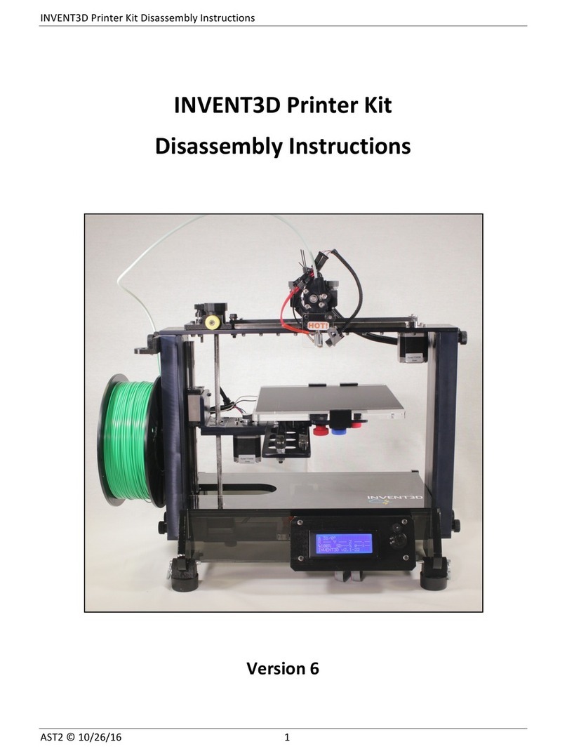
INVENT3D Printer
Operating Instructions & Troubleshooting Guide
Version 6

INVENT3DTM Printer Operating Instructions and Troubleshooting Guide
AST2 © 10/26/16 Page 2
TABLE OF CONTENTS
I. Overview of Printer Components………………………………………………………………………….. 3
II. Turning the Printer On and Off……………………………………………………………………………… 8
III. Overview of Printer Interface………………………………………………………………………………... 9
IV. Loading / Unloading of Filament…………………………………………………………………………… 12
V. Calibrating Z-axis Limit Switch End stop……………………………………………………………….. 14
VI. Leveling the Print Board………………………………………………………………………………………. 14
VII. Converting .stl File to G-code………………………………………………………………………………… 18
VIII. Printing a Part and Removing Part from Print Board……………………………………………… 21
IX. Replacing BuildTak……………………………………………………………………………………………… 23
X. Troubleshooting Guide and Operating Videos ……………………………………………………… 24
Filament
Print Quality
LCD
Power Issues
Print Board
Hot End
Limit Switch
Z-axis
OPERATING VIDEOS
Videos are available on YouTube and INVENTORcloud website (www.inventorcloud.net)
Installing Slic3r: https://youtu.be/-kWy8JPh2IQ
INVENT3D – Keys to Success: https://youtu.be/4-TP87f_Dtk
Changing Filament: https://youtu.be/GkhGFjlLo9Y
Part Removal: https://youtu.be/YJ2lwoVA1l4
Print Board Leveling: https://youtu.be/t5xmp9knYew
Routine Maintenance: https://youtu.be/GVPg4gXYw9w
Z-Axis Calibration: https://youtu.be/jwzYRii9fM0

INVENT3DTM Printer Operating Instructions and Troubleshooting Guide
AST2 © 10/26/16 Page 3
I. OVERVIEW OF PRINTER COMPONENTS
X, Y and Z Axes
The INVENT3D printer creates three dimensional objects by moving the printer hot end
assembly and print board along X, Y, and Z axes.
o X-axis: The printer hot end assembly moves along the X-axis, located on the top of
the printer. The 0 position on the X-axis is the farthest left position along the X-axis
rail, closest to the Z-axis lead screw. Movement along the X-axis is powered by the X-
axis motor, which hangs from the top of the printer on the right side.
o Y-axis: The print board itself moves along the Y-axis rail toward the front or back of
the printer. The 0 position on the Y-axis is the furthest toward the back of the printer,
toward the power plug. Movement along the Y-axis rail is powered by the Y-axis
motor, which hangs from the print board assembly.
o Z-axis: The print board assembly moves up and down along the Z-axis lead screw,
located on the left side of the printer. The 0 position on the Z-axis is the uppermost
position on the lead screw. Movement along the Z-axis is powered by the Z-axis
motor, which is attached to the bottom frame plate.
o Limit Switches: Each of the three axes utilizes a limit switch to detect the 0 point
along the axis. Each axis has a limit switch end stop that activates the limit switch.
Z
-
axis
Y
-
axis
X
-
axis
Z
-
axis
motor
Y
-
axis
motor
X
-
axis
motor

INVENT3DTM Printer Operating Instructions and Troubleshooting Guide
AST2 © 10/26/16 Page 4
The X-axis and Y-axis limit switch end stops are fixed. The Z-axis end stop is
adjustable to allow for a wider range of adjustment when leveling the print board.
Please see Section V for more information on calibrating the Z-axis end stop, and
Section VI for more information on how to level the print board.
Printer Hot End Assembly
The printer hot end assembly is the mounted on the top of the printer and moved horizontally
along the X-axis. The printer hot end assembly is comprised of two main components: the
extruder motor and the hot end. The extruder motor sits on top of the assembly, and it pushes
the filament to the hot end. The hot end sits below the extruder motor, and it heats the
filament to the specified temperature. The filament then passes through the hot end nozzle.
The hot end has a thermistor embedded which relays the temperature of the hot end to the
printer’s operating program which is referred to as firmware and is located in RAMBo board.
Y
-
axis Limit
Switch

INVENT3DTM Printer Operating Instructions and Troubleshooting Guide
AST2 © 10/26/16 Page 5
Additionally, the printer hot end assembly includes two fans. These fans turn on when the
hot end temperature rises above 50 C, and turn off when the hot end temperature is below
50 C. Both fans run at the same speed and cannot be adjusted. The upper fan cools the hot
end and extruder motor so that heat from the hot end does not rise up and cause the filament
to melt inside the extruder drive. The upper fan should never be disconnected or turned off
while the hot end is above 50 C. The lower fan cools the layers of the printed part quickly to
allow for spherical and non-supported shapes to be printed. The lower fan may be turned off
before or during print using the quick disconnect on its wiring. Some part geometries may
print better without the lower fan.
Print Board Assembly
The print board assembly is located in the center of the printer. The print board itself is held
in place by three clamps, one in the front and two in the rear. While the two clamps at the
rear are fixed in place, the front clamp can slide out by loosening the blue thumb screw that
locks it in place, which allows the print board to be removed. The print board should always
be securely locked in place while printing and the print board should always be removed
before removing a part from the print board. The print board is mounted to the print board
plate via the clamps. The print board plate is held in place by three red thumb screws that
are used to adjust the level of the print board with respect to the hot end. For more
information on board leveling please see Section VI. The print board plate and print board
move along the Y-axis rail toward the front and rear of the printer. The entire print board
assembly moves up and down along the Z-axis via the Z-axis lead screw. For the best results,
the print board assembly should be approximately 2” or more below the hot end before
starting a print.
Extruder
Motor
Print Board
Assembly
Hot End

INVENT3DTM Printer Operating Instructions and Troubleshooting Guide
AST2 © 10/26/16 Page 6
Z-axis Components
The Z-axis components consist of the Z-axis motor with lead screw, the lead screw knob, lead
screw lock, and Z-axis end stop. The Z-axis motor moves the print board assembly up and
down via the lead screw. The lead screw knob sits on top of the lead screw, and turning the
knob by hand allows the user to manually raise and lower the print board as needed. The
lead screw lock consists of a yellow thumb screw and housing and is located on the top frame.
Tightening the yellow thumb screw will lock the lead screw in place, which is useful for
leveling the print board and calibrating the Z-axis end stop. Be sure that the yellow
thumbscrew is loose before attempting to print; starting a print with the Z-axis locked
may damage the printer. The Z-axis end stop is a black thumb screw located on the top of
the printer. The screw engages the Z-axis end stop, telling the printer that the 0-position on
the Z-axis has been reached. The Z-axis end stop is calibrated manually to provide for a
greater range of adjustment when setting the gap between hot end and the print board.
Wiring
All wired components connect to the RAMBo circuit board mounted to the bottom of the
printer. Wired components include 4 motors (X-axis, Y-axis, Z-axis, extruder), three limit
switches (X-axis, Y-axis, Z-axis), two fans, hot end, thermistor, LCD screen, and power.
Lead Screw
Knob
Z
-
axis
End Stop
Lead Screw
Lock
Lead Screw

INVENT3DTM Printer Operating Instructions and Troubleshooting Guide
AST2 © 10/26/16 Page 7
For ease of differentiation, wiring for the motors and limit switches are color coded using zip
ties. The X-axis motor and X-axis limit switch have green zip ties, the Y-axis motor and Y-axis
limit switch have yellow zip ties, the Z-axis motor and Z-axis limit switch have orange zip ties,
and the extruder motor has a clear zip tie.
Filament
The INVENT3D Printer uses 1.75mm PLA (polylactic acid) filament. PLA is a bio-degradable
polymer created from various plant products including corn and potatoes. PLA is a type of
thermoplastic, becoming soft and moldable when heated and returning to solid when cooled.
PLA is available in a wide variety of colors. It may be purchased online or from
INVENTORcloud directly. The INVENT3D Printer is not compatible with ABS or any filament
which requires a heated print board.
The filament spool hangs from the filament spool holder on the left of the printer. The side
of the filament spool with the deeper cut-out should always be facing the printer. Filament
runs from the spool, through the filament guide mounted to the top of the left channel of the
printer, through the guide tube, and into the extruder drive.
Hot End
Power
Thermistor
LCD Display
Limit
Switches
Motors

INVENT3DTM Printer Operating Instructions and Troubleshooting Guide
AST2 © 10/26/16 Page 8
II. TURNING THE PRINTER ON AND OFF
To turn on the printer, plug in the power cable to the back of the printer and plug the power supply
into an outlet. To turn off the printer, disconnect the power supply. It is recommended to plug the
printer into a surge protector and use the power switch on the surge protector to turn the printer on
and off. To prevent plugging the hot end, be sure that the hot end temperature is less than 50
C before turning off the printer. The fans should turn off at 50 C.

INVENT3DTM Printer Operating Instructions and Troubleshooting Guide
AST2 © 10/26/16 Page 9
III. OVERVIEW OF PRINTER INTERFACE
The INVENT3D Printer is controlled by the user via the control knob on the front of the LCD. Rotate
the knob to the left or right to scroll through menu options. Push the knob in to select the highlighted
field. The first option in any menu is always go up a level, and it will always have an up arrow next
to it. Subsequent options are either actions or sub menus. Sub menus are indicated by an arrow
pointing to the left.
The following section outlines some firmware options. Printer settings and commands in the
firmware that should not be adjusted are highlighted in red. It is not recommended that the
user select or adjust the fields highlighted in red as doing so may prevent the printer from
functioning properly and can damage the printer.
Info Screen
When INVENT3D printer is plugged in, the LCD will light up and the Info screen will be displayed.
The Info screen is the home screen, and after a short period of inactivity, will return to the Info screen.
The Info screen displays the following information:
Temperature: Current temperature of hot end/specified temperature of hot end displayed
in Celsius. When not printing, the specified temperature should be 0 C. When printing, the
specified temperature should be 220 C. The fan turns on at 50 C when heating and turns off
at 50 C when cooling. When not operating, the left setting should show room temperature.
X: Coordinate of hot end on X-axis
Y: Coordinate of hot end on Y-axis
Z: Coordinate of hot end on Z-axis
FR %: Feed rate percentage which determines print speed. Default is 100%. Increasing from
100% will increase speed but slightly lower quality. Decreasing from 100% will decrease
speed but slightly improve quality. Rotating the control knob will change the feed rate if the
rate has been changed in the “tune” menu on the LCD.
SD%: Completion percentage of the part being printed in terms of number of layers
complete.
Info Screen

INVENT3DTM Printer Operating Instructions and Troubleshooting Guide
AST2 © 10/26/16 Page 10
Print Time (represented by image of clock): Time elapsed from start of print. The clock will
continue to run after print is completed until the printer is configured for another print or is
unplugged. The time to complete print will be displayed in the Notification field when print
is finished.
Notification (text field at bottom of screen): Changes based on status of printer. When the
printer is turned on the notification field will display the current firmware installed on the
printer. After a part is selected for print the notification field will display “Heating...” While
the part is printing the notification field will display “Heating done.” When the part is finished
the time to complete print will be displayed.
Home Screen
Clicking (pushing in) the control knob will bring up the Home screen, which allows the user to select
one of three printer sub menus as follows:
Prepare: Prepare printer to print.
Control: View and change print parameters. It is not recommended to change print
parameters from the control screen as changing them could prevent the printer from operating
properly.
Print from SD: Print G-code files saved to the SD card.
Prepare Screen
The Prepare screen allows the user to perform all functions necessary to prepare the printer to print.
The Prepare screen allows the user to select from the following options:
Disable Steppers: Cuts power to motors and allows motors to move.
Auto Home: Hot end moves to coordinate (0,0,0).
Preheat PLA: Heats hot end to 225 C to allow loading and unloading of filament.
Cooldown: Sets temperature of hot end to 0 C. Hot end will cool down to room temperature.
Switch Power Off: Turns off power to hot end.
Move Axis: Submenu that allows user to move motors in increments from .1mm to 10 mm.
Used when loading and unloading filament. This function cannot be performed when setting
is more than 1mm.
Move Axis Submenu
The Move Axis submenu allows the user to move the X, Y, Z, and extruder motors in increments of
.1mm, 1mm, and 10mm by rotating the control knob. After selecting Move Axis, the user will be able
to select the distance to move the motor. It is recommended to always select 1 mm. After selecting
the distance, the user will be able to select the motor that they wish to move. After selecting the
desired motor, a control screen will be brought up and the user can turn the knob clockwise or
counterclockwise to move the motor forward or backward. Push the control knob in to go back to
the motor select submenu.

INVENT3DTM Printer Operating Instructions and Troubleshooting Guide
AST2 © 10/26/16 Page 11
Control Screen
It is not recommended that the Control Screen and its submenus be used as changing the print
parameters may cause the printer malfunction and cause damage. Control Screen options are:
Temperature: Changes printer parameters with respect to temperature.
Motion: Changes printer parameters with respect to motion.
Store Memory: Save changes made in temperature and motion.
Load Memory: Restore saved changes previously made in temperature and motion.
Restore Failsafe: Restore to default temperature and motion settings.
If any changes are made to temperature and motion settings, they can be undone by selecting
Restore Failsafe.
Print From SD Card Screen
The Print From SD Card screen allows the user to select from G-code files that were saved to the SD
card. G-code files are created by the slic3r program based on a .stl CAD model. Upon clicking on
Print From SD Card using the control knob, the printer will display filenames of the G-code files
saved to the SD card. If the most recent file saved is not last on the list, the SD card is full. This can
impact printing. Use a new SD card or deletes files from current SD card. Rotating the control knob
allows the user to select the desired file to print. Upon selecting a file, the printer will begin heating
up and preparing to print.
Options Only Available During Print
These options, in addition to Control described above, are only displayed on Home Screen while the
printer is printing
o Tune: Allows the user to change certain print parameters specifically for the ongoing print:
Speed: Change print speed. Slower printing yields higher quality while faster
printing results in lower quality.
Nozzle: Change temperature of the hot end. 220 C is the default.
Fan Speed: Always set at 0 as the fan speed of the INVENT3D printer is not
adjustable.
Flow: Change flow rate through the hot end nozzle. Should always be set at 100.
o Pause Print: It is not recommended to pause for more than 1 minute as melted filament will
drip onto the part.
o Stop Print: Stops the print, and the print may not be resumed. The hot end will not cool
down automatically if the print is stopped. The user will need to navigate to and select the
Cooldown option described above to begin the cooling process.

INVENT3DTM Printer Operating Instructions and Troubleshooting Guide
AST2 © 10/26/16 Page 12
IV. LOADING / UNLOADING FILAMENT
It is important to remember that the INVENT3D printer is only compatible with 1.75mm PLA.
Loading Filament
1. Place the spool on the spool holder. Each filament spool has one side where the center is cut
deeper; this side should be facing the printer to ensure that the spool seats correctly on the
holder and that material does not get trapped behind the spool and impair printing.
2. Locate the end of the filament and cut away any bent or twisted filament from the end.
3. Feed filament through the filament guide (accommodates filament wound clockwise or
counter-clockwise) so that it is coming off spool on the side that the filament is feeding.
4. Run filament through guide tube.
5. Insert filament into filament drive guide hole.
6. Turn on printer, go to Info screen, select Prepare, and then select Preheat PLA.
Filament
drive guide
hole
Guide
Tube
Filament
Guide

INVENT3DTM Printer Operating Instructions and Troubleshooting Guide
AST2 © 10/26/16 Page 13
7. Wait until temperature of hot end reaches 200 C.
8. Go to Info screen, select Prepare, select Move Axis.
9. Under the Move Axis submenu, select Move 1mm, then select Extruder. Extruder motor will
not move if 10mm is selected.
10. Rotate control knob clockwise until filament comes out of the hot end.
11. If filament does not feed through hot end, the hot end is not seated flush in its mount. Push the
hot end as far as possible into its mount.
12. If filament still does not feed, remove the extruder top that holds the extruder motor into place.
Lift up the extruder motor and extrude out about 1” of filament. Insert filament into the top
hole of the hot end and set the extruder motor back on the extruder bottom. Replace the
extruder top to lock down the extruder motor. Extrude filament until it comes through the hot
end nozzle. The filament will not feed if hot end temperature is less than 200 C.
13. When using a new roll of filament, watch how the filament is leaving the spool when
beginning to print as well as when spool is placed on the printer. If the filament is wound too
tightly, it can jump off the spool and become trapped between the spool and the printer.
Unloading Filament
1. Turn on printer, go to Info screen, select Prepare, and then select Preheat PLA.
2. Wait until temperature of hot end reaches 200 C.
3. Go to Info screen, select Prepare, select Move Axis.
4. Under the Move Axis submenu, select Move 1mm, then select Extruder.
5. Rotate control knob counter-clockwise until filament backs out of the hot end.
6. Do not attempt to unload filament without first heating the hot end. The extruder motor will
not function if the hot end is not at least 200 C.
Top
Hole of
Hot End

INVENT3DTM Printer Operating Instructions and Troubleshooting Guide
AST2 © 10/26/16 Page 14
V. CALIBRATING THE Z-AXIS LIMIT SWITCH END STOP
Calibrating the Z-axis limit switch end stop is required if the user is unable to level the print board
using the three red thumb screws, which occurs when the thumb screw falls out of the hole or cannot
be tightened any further or are too loose. Additionally, the Z-axis limit switch end stop will need to
be recalibrated if it is removed from the printer or becomes loose. The Z-axis limit switch end stop
should only be calibrated when the hot end is cold. Refer to Section VI for instructions on board
leveling and setting hot end gap.
VI. LEVELING THE PRINT BOARD
It is imperative to understand each component of the schematic to successfully and easily
level the board.
The print board must be level for printer to print correctly. The print head is too close if the printed
filament is transparent or if the hot end touches the print board. The print head is too far away if the
printed filament is lifting up from the print board or accumulating around the hot end. Obtaining a
level board is integral to successful printing and production of high quality parts. Therefore, it is
imperative to check and maintain the level of the print board before printing begins.
Print board
Z
-
axis knob
Z
-
axis end stop
Z
-
axis lock
Red thumb screws
Hot end
Plastic mount
Print board
plate
Z
-
axis limit
switch
Gap
Diamond plate

INVENT3DTM Printer Operating Instructions and Troubleshooting Guide
AST2 © 10/26/16 Page 15
1) Remove the print board.
2) Visually locate the ends of the red thumbscrews in the print board plate.
3) Tighten all three red thumbscrews until they are flush with top side of the print board plate.
4) Loosen each red thumbscrew 1 ½ turns. Confirm that each screw is recessed the same amount
below the surface of the print board plate. NOTE: If you are having difficulty determining how
much to turn the red thumbscrews, re-tighten all three red thumbscrews until they are flush with
the top of the print board plate, then place a mark on the right side of each red thumbscrew.
5) Grab the print board plate and gently wiggle it up-and-down and back-and-forth to make sure
the wave springs are properly seated in the print board spacer, and to check for any loose screws
missed during assembly. Tighten any screws that feel loose.
6) Install the print board by pressing it firmly into the rear print board clamps, then press the front
board clamp firmly against the print board, and finally secure the front print board clamp by
tightening the blue thumb screw located below the print board.
7) Loosen the Z-axis end stop screw so that the end of the screw extends no more than ½” from the
bottom side of the top plate.
8) Place a business card or index card (approximately 0.2mm) on the print board.
9) Move the hot end and the print board so that the hot end is located directly over the center of the
print board. Using the Z-axis knob, lift the print board until the card is just slightly trapped by the
hot end. The card should be moveable with only slight resistance. NOTE: Try to not press down
on the print board when moving the card as this will make the gap between the hot end and the
print board appear larger than it is. (If the Z-axis end stop screw prevents you from lifting the
print board high enough, go back and redo Step 7 above.)
10) While holding the Z-axis knob, hand tighten the yellow Z-axis lock thumbscrew to lock the print
board so it can’t move up or down along the Z-axis.

INVENT3DTM Printer Operating Instructions and Troubleshooting Guide
AST2 © 10/26/16 Page 16
11) Move the hot end and print board to position the hot end at Blue Circle 1 in the picture
(approximately 1” from the right side of the print board). Using the card, measure the gap
between the hot end and the print board. Adjust only the right red thumbscrew (Red Circle 1)
until the card is moveable with only slight resistance.
12) Repeat Step K above, moving the hot end to Blue Circle 2 in the picture (approximately 1” from
the left side of the print board) and adjust only the front red thumbscrew (Red Circle 2).
13) Repeat Step K above, moving the hot end to Blue Circle 3 in the picture (approximately 1” from
the left side of the print board) and adjust only the rear red thumbscrew (Red Circle 3).
14) Repeat the last three steps with each red thumbscrew to confirm that you have a consistent gap
between the hot end and the print board in all three locations.
15) Gently press and release the Z-axis limit switch and listen for it to click. Now slowly tighten the
Z-axis end stop screw until you hear it press the Z-axis limit switch and make it click.
16) Loosen the yellow Z-axis lock thumbscrew, then use the Z-axis knob to lower the print board a
few inches.

INVENT3DTM Printer Operating Instructions and Troubleshooting Guide
AST2 © 10/26/16 Page 17
17) To check the adjustment of the Z-axis limit switch:
1. Press the LCD button; menu will display.
2. Go to “Prepare” and select; menu will display.
3. Go to “Auto Home” and select.
4. The hot end and print board assembly will move to 0,0,0 position. NOTE: If you hear any
noise, stop and troubleshoot. Causes may include: belts may not be aligned, yellow
thumbscrew not released, may need to apply grease to Z-axis lead screw, end stop switches
are not functioning properly, etc.
5. Tighten the yellow Z-axis lock thumbscrew to lock the print board so it can’t move up or down
along the Z-axis.
6. Press LCD button; menu will display.
7. Go to “Prepare” and select; menu will display.
8. Go to “Disable Steppers” and select. This will allow you to move the hot end and print board
to check the gap with the card. The card should be moveable with only slight resistance.
9. If the gap is correct, you’re done. If the gap is too tight, turn the Z-axis end stop screw ¼ turn
clockwise. If the gap is too large, turn the Z-axis end stop screw ¼ turn counter-clockwise.
10. Loosen the yellow Z-axis lock thumbscrew, then use the Z-axis knob to lower the print board
a few inches.
11. Re-check the adjustment of the Z-axis limit switch by repeating the previous 10 steps until
the gap is correct.
NOTE: This full process for print board leveling typically only needs to be done when you are
assembling the printer from the kit or if the print board get way out of level. For day-to-day use the
print board should stay level. Always remove the print board before attempting to remove a printed
part from the print board. Attempting to remove a part from the print board while it is still connected
to the printer is a quick way to get your print board way out of level, and very well may damage the
printer.

INVENT3DTM Printer Operating Instructions and Troubleshooting Guide
AST2 © 10/26/16 Page 18
VII. CONVERTING .STL FILE TO G-CODE
CAD files saved as .stl must be converted to a G-code file prior to printing on INVENT3D using a slicer
program. The G-code file tells the printer how to print a desired part, controlling print parameters
such as temperature, speed, orientation, and scale as well as part options such as fill type (rectilinear,
honeycomb, etc.) and support material usage. Default print parameters are calibrated specifically for
the INVENT3D printer and cannot be changed. The print settings defined in the slicer program will
always take precedent over the settings programmed into the INVENT3D printer firmware.
The recommended slicer program for use with the INVENT3D printer is slic3r, an open source slicing
program. Instructions for downloading slic3r are posted to the INVENTORcloud website at
www.inventorcloud.net It is absolutely essential that slic3r program be downloaded from the
INVENTORcloud website to prevent printer damage and provide quality prints. This assures that the
settings correspond to the INVENT3D Printer. Using settings designed for any other printer will
damage the INVENT3D Printer and/or result in poor quality.
IMPORTANT: Do not use a slicer program that is not calibrated specifically for INVENT3D printer as
doing so may break the printer. Do not download the program from any other generic website.
Instructions on how to convert a .stl file to a G-code file using slic3r:
1. Open slic3r from desktop button.
2. Use the Platter screen to set up the print.
2.1. Select Add, then search for the file to be printed
2.2. Select file and click Open.
2.3. Double click on drawing to view in 3D.
2.3.1. Be sure the object is facing the direction desired for printing.
2.3.2. If rotation is needed, use the Rotate buttons change model orientation. The design may
need to be rotated in the CAD program.
2.4. Scale button allows for increasing or decreasing the size of the part to be printed. This size
of the part is shown in mm. Verify that part is correct size.
2.5. To copy part, click “+“ to add a copy of the part, or use ”-“ to subtract a copy of the part.
2.6. The Add button allows adding another file to the same print.
2.7. Delete / Delete All will allows removing parts from print.

INVENT3DTM Printer Operating Instructions and Troubleshooting Guide
AST2 © 10/26/16 Page 19
2.8. Arrange moves the location of part(s) on the board. It is recommended to always use this
when printing multiple parts.
3. Use Print Settings to change parameters of part to be printed.
NOTE: Changing print settings should only be done by someone with extensive experience with
3D printing. It is recommended that pre-programmed, default settings be used for normal
printing which can be found at www.inventorcloud.net.
3.1. Layer Height alters the height for each individual layer. It can be used to change print speed.
A layer height of 0.15 is recommended.
3.2. Infill – 20 to 40% recommended, do not exceed 65% as this will plug hot end.
3.2.1. Fill Pattern –Changes the pattern of the fill of the part. Rectilinear is recommended.
3.2.2. Top/Bottom Fill – Changes the pattern of the fill of the top and bottom of the part to
be printed. Rectilinear is recommended.
3.2.3. Combine Infill Every – Should be set at 1 layer.
3.2.4. Solid Infill Every – Should be set at 0 layers.
3.2.5. Fill Angle – Should be set at 45 degrees.
3.2.6. Solid Infill Threshold Area – Should be set at 70mm.
3.2.7. Only Retract When Crossing Perimeters – Should be checked.
3.3. Skirt and Brims – It is not recommended to change defaults.
3.4. Support Material
3.4.1. Generate Support Material - Should be checked if part will not print without support.
3.4.2. Raft – Do not use. It should always be 0.
3.4.3. Pattern – Changes the pattern of the support material. Pillars is recommended.
3.4.4. Pattern Spacing – A setting of 4 mm is recommended.
3.4.5. Don’t Support Bridges – Should be checked.
3.5. Notes – Notes are not needed.
3.6. Output options – It is not recommended to change default settings.
3.7. Multiple Extruders – It is not recommended to change default settings.
3.8. Advanced – It is not recommended to change default settings.

INVENT3DTM Printer Operating Instructions and Troubleshooting Guide
AST2 © 10/26/16 Page 20
3.8.1. Filament Settings is used to change the parameters of the filament to be used for the
print. It is recommended to leave default settings as they are programmed for the
INVENT3D Printer.
4.1. Filament
4.1.1. Diameter – Should be set at 1.75mm.
4.1.2. Extrusion Multiplier – Should be set at 0.95.
4.1.3. Temperature – Should be set at 220°C / 220°C. It is recommended to change
temperature using the 3D printer itself and not in the slic3r program.
4.1.4. Board – Should be set at 0°C /0°C. The INVENT3D printer does not use a heated board.
4.2. Cooling – It is recommended not to change default settings.
5. Printer Settings – It is recommended not to change default settings as they have been
programmed for the INVENT3D printer.
6. Go back to Platter when finished with the various Settings
6.1. Select Export G-code.
6.2. Save file on SD card. Be certain that file is completely saved before moving SD card.
6.3. Insert SD into INVENT3D printer to print.
7. The CAD design must in millimeters (mm) or the slicer program will show a very small print if
the design is in inches. Conversion to mm is required.
Other manuals for INVENT3D
1
Table of contents
Other AST2 3D Printer manuals