GN10VP/GN15VP/GN20VP
Continuously-variable Pattern Condenser Mini-gooseneck Microphone with Power LED
Description
The GNVP is a series of continuously-variable pattern, quick-mount,
miniature-gooseneck condenser microphones designed primarily
for speech and vocal pickup. Special attention has been taken to
design the GNVP series with improved RF immunity to greatly
reduce susceptibility to radio interference from GSM based cell
phones, PDA/cell phones with walkie-talkie capability and other
similar devices. The integral 80Hz, 12dB/oct hi-pass filter removes
unwanted low frequency energy. The advanced, transformerless
electronics are self-contained to simplify installation. Available in
10", 15" and 20" lengths, the GNVP may be mounted on lecterns,
pulpits and conference tables with the included mounting hardware
or with other options available from Astatic.
A status indicator LED is located on the XLR housing that is visible
to the speaker indicating that the microphone is operational. The
LED on/off switch as well as polar pattern adjustment are hidden
from unqualified tampering on the PCB within the XLR housing.
The Astatic GNVP has a variable polar pattern so it can shorten
the list of products an audio system designer requires when
miniature-gooseneck condenser microphones are indicated. From
omnidirectional to cardioid, hypercardioid, figure-eight and all tight
or wide directional polar patterns in between, an installer can
precisely tailor the polar pattern for optimum performance. One
gooseneck condenser microphone can suit almost any challenge
when tasked to perform in business, government, worship, and
media production.
Features
• Continuously-variable polar pattern
• RF (radio frequency) resistant architecture
• Status LED (defeatable)
• Controls secured within the XLR housing
• Available in three lengths (10", 15" & 20")
• Quick-mount format
• Balanced transformerless output circuitry
• Integrated hi-pass filter for elimination of unwanted
low frequencies
• Silent, durable, dual-flex pipe design with strong positioning
memory
• Non-reflective matte-black finish
• Included shock mount (approx. 20dB noise isolation)
• Included XLR-F type locking flange mount
• Included windscreen
Astatic Commercial Audio Products
6573 Cochran Rd. Building ISolon, Ohio 44139 U.S.A.
Tel: (440) 349-4900 Fax: (440) 248-4902 Sales: (800) 421-3161
www.astaticinstalled.com
©2007 Astatic Commercial Audio Products
Part No. 46873-81-00 rev01 Jan2007
1. Mark the center of the mounting location.
Be sure to check the underside of the
surface for obstructions.
2. Using a 7/8" hole saw or drill bit, cut the
centered hole for the cable and bottom of
the mount to pass through the surface.
3. Fit the mount into the hole so that the
flange sits flat on the surface. Mark the
three mounting holes around the flange.
4. Remove the mount from the hole and
pre-drill the marked mounting holes for
screws appropriate for the installation.
5. Make all final audio connections to the
XLR connector.
6. Mount the FM-2A to the surface.
1. Mark the center of the mounting location.
Be sure to check the underside of the
surface for obstructions.
2. Using a hole saw cut a centered 2” hole
in the mounting surface.
3. Fit the GSM-2 into the hole so that the
flange sits flat on the surface. Mark the
three mounting holes around the flange.
4. Remove the GSM-2 from the hole and
pre-drill the marked mounting holes for
screws appropriate for the installation.
5. Attach the GSM-2 to the surface.
Two-Year Limited Warranty
Astatic Commercial Audio Products hereby warrants that this product will be free of defects in material and workmanship for a period of two years from the date of purchase. In the unlikely
event that a defect occurs Astatic will, at its option, either repair or replace with a new unit of equal or greater value. Retain proof of purchase to validate the purchase date and return it with
any warranty claim.
This warranty excludes exterior finish or appearance, damage from abuse, misuse of the product, use contrary to Astatic’s instructions or unauthorized repair. All implied warranties,
merchantability, or fitness for a particular purpose is hereby disclaimed and Astatic hereby disclaims liability for incidental, special or consequential damages resulting from the use or
unavailability of this product.
This warranty gives you specific legal rights and you may have other rights that vary from state to state. Some states do not allow the exclusion or limitation of incidental or consequential
damages or limitations on how long an implied warranty lasts, so the above exclusions and limitations may not apply to you.
Note: No other warranty, written or oral is authorized by Astatic Commercial Audio Products.
Shipping Instructions
Please call our customer service department at 440-349-4900 for a pre-approved return authorization number.
Carefully repack the unit and return the insured package to: Astatic Commercial Audio Products, 6573 Cochran Road, Building I, Solon, Ohio 44139. RETURNS WITHOUT A
PRE-APPROVED RETURN AUTHORIZATION NUMBER WILL BE REFUSED.
If outside the United States, contact your local dealer or distributor for warranty details.
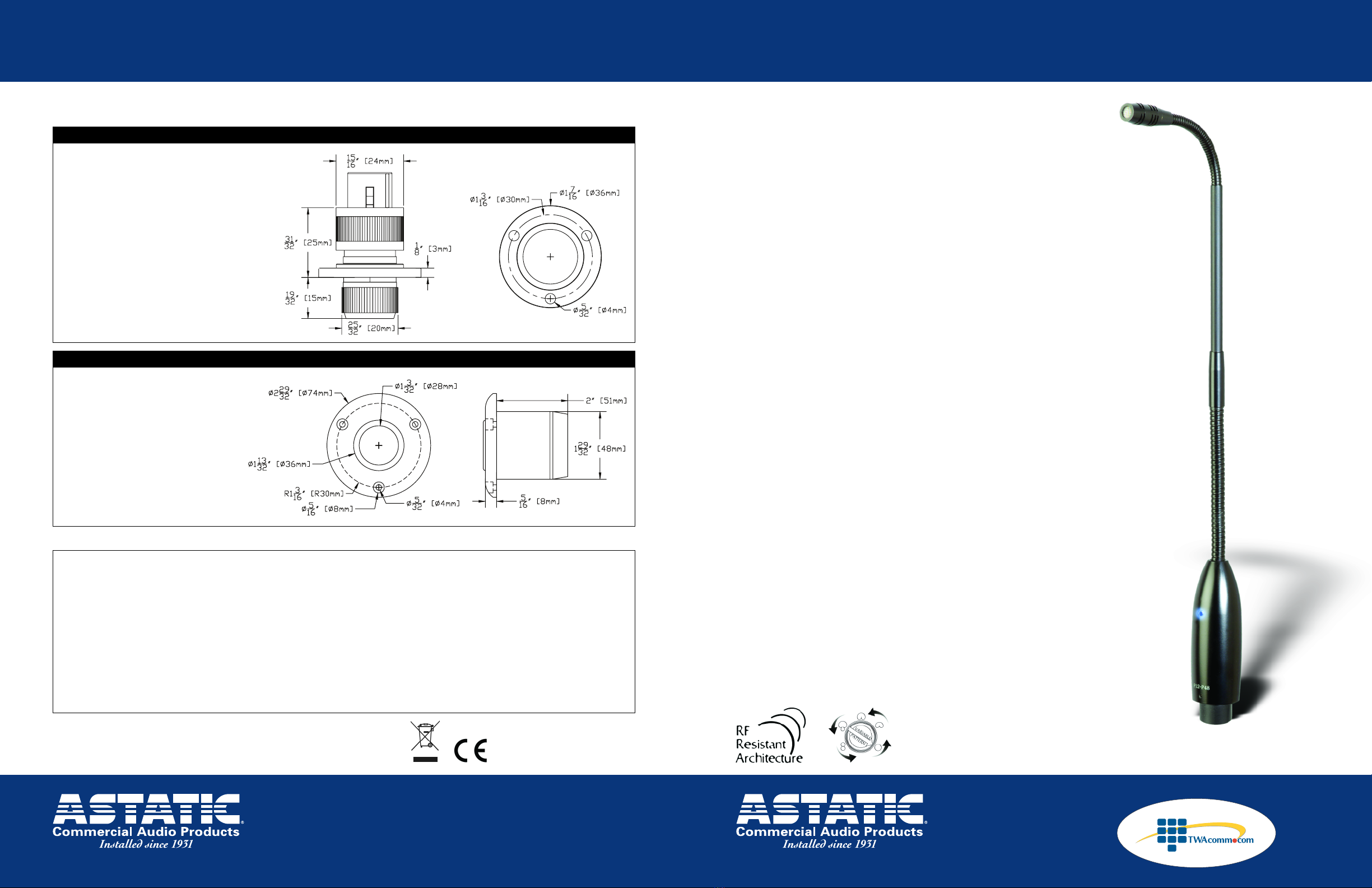
Dimensional Drawings
(not shown actual size)
4 of 4 1 of 4
FM-2A Locking Flange Mount Installation
GSM-2 Shock Mount Installation
Sold by:
http://www.TWAcomm.com
Toll Free: (877) 389-0000


