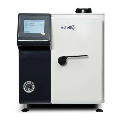
Astell SWIFTLOCK User manual

Powerscroft Rd
Sidcup
Kent
DA14 5DT
United Kingdom
Tel 0208 300 4311
Fax 0208 300 2247
SWIFTLOCK
Multi-Purpose
Cylindrical Sterilizer
Electrically
Heated
INSTALLATION
INSTRUCTIONS
OPERATING
INSTRUCTIONS
MAINTENANCE
INSTRUCTIONS
SERVICE MANUAL
Complete Program Entry and
Operating instructions for the
Programmable Control System of
this STERILIZER detailing Front-
panel operation , Display and
Keyboard are provided in a separate
Astell Manual ;-Part No. MXN487
Part No MXN488 iss01 ed a
PDF created with FinePrint pdfFactory Pro trial version http://www.fineprint.com

MXN488 iss01 ed A page 1
1
CONTENTS
INTRODUCTION
2 Introduction , Log Book ,Machine
Specification Document Issues
3. Climatic Conditions , Storage and use.
Battery Backup.
INSTALLATION
4. Water/Steam services, Drainage
Safety Valve ; Drain Valve ; Vent Valve
5. Steam Inlet ; Condensate return (Steam
Heated Models)
6 Electrical installation ; Power supply cable
7 Power Supply Electrically Heated Models
8 Fuse Ratings Electrically Heated Models
9 Heater/Power wiring, 380-440V 3-Phase,
Heater/Power wiring, 200-240V 3-Phase
OPERATION
10 Operation- general description
Setting Parameters-1-Program Models
11 OPERATION-SWIFTCLAVE
Electrically Heated Models
(Copy and post near to Sterilizer)
12 OPERATION-SWIFTCLAVE
Electrically Heated Models
(With Load Sensing Timing)
(Copy and post near to Sterilizer)
13 OPERATION - DETAILED REVIEW.
Lid/Door Interlocks, Heating ,
Freesteaming Timing , Sterilize Timing
Load Sensed Timing (Option) ;
14 Load Simulators/Cooling locks
. Cooling System and Cooling Locks
15. Selection of a Cooling Lock ; Thermal Lag
& the dummy load
16 Media Holdwarm
17 Water Quality.
Overflow Warning Pipe
18 Chamber Cleaning-
Chamber Cleaning-Steam Heated Models
LOADING and INTERLOCKS
19. Load Containers and Loading
20. Safety Door Interlocks
[UK HSE. Guidance Note PM73]
MAINTENANCE AND TECHNICAL
21. Periodic Maintenance
Safety Valve Testing
22 Thermocouple Access Ports
Load Sensing Probes
23. Fuses, Overtemperature Cutout
Technical notes
24. Certificate Of Examination -
25. Temperature/Pressure Corellation chart
26. List of Electrical Drawings available.
(drawings supplied on request .)
Consult ASTELL sevice Dept. for
mechanical drawings.
DRAWINGS
FSTERILIZERS ARE HAZARDOUS
IF MISUSED
Do not operate this machine if unsure of
operating procedures .
PDF created with FinePrint pdfFactory Pro trial version http://www.fineprint.com

MXN488 iss01 ed A page 2
2
INTRODUCTION
The SWIFTLOCK range are modern, functional general - purpose laboratory
STERILIZERS designed with ease of use in mind . They feature the proven
SWIFTLOCK CLOSURE PAT system to give easy and rapid opening of the chamber,
together with an easy-to use Single- or Multi-program control system, to facilitate a
variety of uses.
GENERAL OPERATION AND LOG-BOOK
Although the historical safety record of laboratory STERILIZERS is good, remember
at all times that they store considerable potential energy, and should be treated with
respect and care. If correctly used and cared for, your ASTELL STERILIZER will
provide long, reliable & safe service.
Pay proper attention to regular maintenance. Never force the locking mechanism, or
operate the machine with any leaks, or incorrectly operating parts.
Report any defects to your Engineering/Supervisor. If deterioration or defects are
noticed, record them in a log book and contact our Service Department .
Record also the results of annual and periodic inspections. Every 4 to 6 weeks is
recommended for periodic checks. Check the logbook before you start using the
machine, as someone else may have recorded a fault of which you are not aware.
MACHINE SPECIFICATION AND CONTROL OPTIONS
The Control System Display will show various items of information when the Mains
Power is turned on , for example...
"SWIFTCLAVE STERILIZER" denotes STERILIZER Type
"ELECTRICAL HEATING" or "STEAM HEATING" "SOFTWARE ISSUE No. xyz"
"PRINTER SELECTED"
"PROGRAM SELECTION BY SUPERVISOR ONLY"....etc.
Please keep a note of these displays ; You may be asked to quote these to assist
the Astell service dept. if requesting service dept. attention .
DOCUMENT ISSUES AND DETAILS
Date
& MR no
Issue Ed. FILENAME
Details of changes and revisions inc. software issues and
associated manuals
300700 0I A MXN488-1.doc
Der from mxn463 electric only #6,-10
PDF created with FinePrint pdfFactory Pro trial version http://www.fineprint.com

MXN488 iss01 ed A page 3
3
CLIMATIC CONDITIONS AND SPECIFICATIONS
Storage of this product in cold or damp conditions may lead to a Hazard or operating
faults if the equipment is put into service before it has dried out and achieved
equilibrium with the surroundings of the operating site.
Place in the area where it is intended to use the equipment.
Do not connect to a power supply.
Allow 48 Hrs to reach Humidity Equilibrium.
CLIMATIC CONDITIONS
OPERATING
Permitted Humidity not exceeding 75% mean non-condensing.
Permitted Temperature range 0-40 C
Do not site the equipment in an area where there are significant quantities
of dust. this will gather on the electronics and cause malfunction.
Do not site the equipment in an area where Spray or fumes from other
equipment may touch the cabinet or cooling vents.
Do not hose down or wash the equipment. The electronics system is not
protected against jets of water.
STORAGE
Permitted Temperature range -10 / +70 C
Humidity not specified but an equalising time is required- see above.
BATTERY BACKUP
Data retention - Main system EEprom . No Battery Required
Real-time Clock ( in Printer Option ) Nicad Rechargeable battery Soldered In.
(Maintains date/time operation when turned off. Not used to store data.)
PDF created with FinePrint pdfFactory Pro trial version http://www.fineprint.com

MXN488 iss01 ed A page 4
4
WATER & STEAM SERVICES &
DRAINAGE PIPEWORK CONNECTIONS.
• The TANK DRAIN outlet must be connected to a suitable Building Drain to carry away
waste water.
• The Safety Valve exhausts into the room.
• A supply of cold Mains water is required
• The Autofill tank Overflow / Warning Pipe must be correctly arranged.
• Electrically heated models are provided with a Chamber Cleaning Drain which may be
connected to the Building Drain .
• Steam heated models require a supply of steam .The Condensate Drain should be
connected to the building drain .
PIPEWORK CONNECTIONS. and installation details
TANK DRAIN OUTLET
This is a 35 mm plastic drainage outlet pipe projecting from the rear of the machine.
It must be plumbed into a building drain , and carries water with a temperature of up to 60C, but
normally ambient-40C. The outlet pipework should be free-draining and have a downward slope of a
min. of 1- in 50 and should not be reduced in diameter. If the length is to exceed 10 metres the whole
of the length of drain pipework should be increased in diameter by at least one size.
MAINS WATER INLET
This is a Plastic Coloured Hose with a 3/4 BSP Female Threaded tap connector similar to a Washing
Machine Inlet Hose. This should be connected to a Cold Water Mains Supply , Minimum 0.5 Bar ,
Maximum 6 Bar pressure. This supply Must be provided with a Shutoff Valve ( a Washing-Machine-
Isolator Valve is suitable ). The supply must provide for a Maximum Flow-rate of 10 litres/minute.
DRIP-TRAY DRAIN
There is no separate driptray drain this is incorporated with the Tank Outlet.
TANK OVERFLOW / WARNING PIPE
This is a White Polypropylene 20mm pipe which projects from the rear of the machine and will carry
overflow water if the Level in the Autofill tank is too high. It should be fed to an open Tundish or drain.;-
U.K. Water Research Council and the U.K. water byelaws require Warning pipe outlets to be visible to
the operator.
SAFETY VALVE
The Safety-Valve exhausts vertically downwards at the rear of the machine close to the floor. When it
operates a large volume of low-velocity steam will be produced .
It must not be connected to any other pipework or altered .
Please see other references in this manual to SAFETY-VALVE TESTING.
AIR INLET
This is a screwed inlet socket fitted inline with a 1-way valve. An optional bacteriological filter is
available which may be-fitted to allow clean air- into the chamber as it cools. Consult your Supplier for
details of suitable filters.
DRAIN VALVE - Electric Heated Models ONLY
The Drain valve permits the Chamber to be drained for cleaning purposes. This is at the rear of the
STERILIZER fitted with a lever action hand-valve. The valve is shut when the handle is at RIGHT-
ANGLES to the pipe. This should be arranged to allow the chamber to be drained regularly. It may be
plumbed into a drain or tundish.
KEEP CLOSED DURING USE & DO NOT OPEN WHEN HOT OR PRESSURIZED.
STEAM HEATED MODELS ONLY
PDF created with FinePrint pdfFactory Pro trial version http://www.fineprint.com

MXN488 iss01 ed A page 5
5
STEAM INLET..
STEAM SUPPLY
This is a 3/8" BSP Screwed Gun-Metal Union. The steam supply should be connected to the gunmetal
union. The STERILIZER may be factory-fitted internally with a pressure reducing valve, .Where fitted
supply pressure should be between 4 and 7 Bar If a Pressure reducing valve is NOT factory- fitted,
steam supply pressure must be reduced to 4 Bar, +0 /- 0.5 Bar with a suitable Pressure Reducing
Valve before reaching the STERILIZER. Please refer to the Rating plate at the rear of the machine for
It is important to fit a pressure gauge into this supply line, after the pressure reduction valve, which will
indicate actual steam pressure available to the machine . A condensate draining steam trap must be
fitted immediately upstream of the STERILIZER, to remove all condensate as Free Water will stop
Sterilizing action.
Steam Supply Problems;-A common fault with installations is that long pipe runs, poor layout or poor
steam quality fill the STERILIZER Chamber up with water. This will be avoided if attention is paid to
Condensate separation. Ensure that the steam supply flow is adequate to feed the machine when
operating - The steam pressure in the line will fall when the machine is HEATING UP .
SUPPLY CONDENSATE RETURN SYSTEM
The steam Supply line must be properly installed. If provision is not made to automatically drain off the
condensate that forms in the supply line the STERILIZER will draw in large quantities of water. this will
stop the Sterilising action, and may cause damage.
Warning ; On new steam systems or those that have cooled beware condensate build-up in lines
which may cause water hammer & damage valves and instruments.
Correct installation and Steam Trap arrangements will avoid this.
STEAM DRAIN OUTLET ( Chamber Condensate )
On Steam Heated Models the Chamber is fitted with an Automatic Chamber Drain. The outlet from
this is the small diameter COPPER pipe at the bottom rear of the machine. It should be connected to a
suitable building drain capable of carrying steam condensate ( at up to 134C ) Connection into the
boiler-house condensate return is not advisable due to the possible bacteriological contamination of
returned condensate if any of the load contaminates the inside of the machine.
This outlet should be connected via an air-break to prevent back-suction.
PDF created with FinePrint pdfFactory Pro trial version http://www.fineprint.com

MXN488 iss01 ed A page 6
6
POWER SUPPLY INLET CABLE
SWIFTCLAVE STERILIZERS are supplied as standard with a fitted Power Supply Cable. Steam heated
Machines have a CEE22 type Power Inlet cable and plug. Electrically heated machines are supplied with
a 5-core or 3-core ready-fitted mains supply cable provided with a standard -type Industrial High-Current
plug. The Cable is of the heavy-duty SY type, Double-Vinyl covered and protected by a woven metal
braid. (Models for 220V 3-phase supplies may have alternative arrangements.)
The STERILIZER has been tested in the configuration in which it is delivered from the factory. Details of
the Supply Voltage and the Current rating, etc are given on the Serial-Number / Rating Plate attached to
the machine.
Cable Alteration
Should it be necessary to alter the supply cable to suit local regulations or arrangements , the new power
supply cable should be arranged in flexible conduit or use similar suitably protected power cable rated to
carry the Maximum Current per Phase for 3-phase machines, and 5 Amps {Single Phase} for Steam
Heated machines. The connections are made to Terminals in the Power Input Box. The Cable should
pass under the lower edge of the rear panel, or through the cutout provided below the Power Input Box,
allowing the panel to be removed for access.
This machine must be wired with a protective earth.
RECORDER POWER FEED
The recorder options include an automatically controlled 240 Volts 1 Amp power outlet via a CEE22
Outlet connector. This is intended to power ONLY an Astell approved Recorder System. Instructions for
use are provided with the Recorder option. Some versions may use a different connector and the output
may also include remote control low-voltage signals.
Do Not Connect Any Other Equipment To This Outlet .
VOLTAGE RATING PLATE
Before attempting an installation, consult the SERIAL NUMBER / RATING PLATE fitted to the machine
which gives supply type and voltage requirements
PDF created with FinePrint pdfFactory Pro trial version http://www.fineprint.com

MXN488 iss01 ed A page 7
7
ELECTRICALLY HEATED MODELS
Consult the SERIAL-No./ VOLTAGE RATING PLATE Sited at the rear of the machine, or on some
models , near the front to one side. The STERILIZER is normally delivered with the supply arrangement
to suit the voltage and supply specified at the time of ordering. Should the Power Lead need to be
altered, Appendix 1, figures show how the 1 or 3-phase supply is connected to the terminals in the power
input box. Several models are available, With different Heaters and Supply wiring. Check the Power
Rating on the Rating Plate and refer to the details below:
[ PLEASE NOTE .. Voltages given are measured phase-to-phase. ]
SWITCHED FUSED SUPPLY ISOLATOR
The Power must be fed from an EXTERNAL SWITCHED FUSED ISOLATOR .This must be sited within
1 M of the machine. Astell STERILIZERs for 380-440 V 3-phase supplies may be supplied with a fitted
power lead nominally 2.5 M long ready-wired to a High-Current IEC power plug. The Site should be
provided with a Power Outlet socket to match the power connector. The following connector types are
fitted -
Supply Rating Fitted Plug on machine Outlet on wall
380-440V
3-Phase models
all heater ratings
CEE17 , EN60-309 , BS4343 415V
3P+N+E PLUG ip44 32 AMP
( RED)
CEE17 , EN60-309 , BS4343 400V
3P+N+E SOCKET ip44 32 AMP
(RED )
200-220V
3-Phase models
all heater ratings
*** Not normally Supplied ***
CEE17 , EN60-309 , BS4343 240V
3P+N+E PLUG ip44 63 AMP
( RED ),
*** Not Normally Supplied ***
CEE17 , EN60-309 , BS4343 240V
3P+N+E SOCKET ip44 63 AMP
( RED ) ,
Suggested Connector alternatives for installations.
Connector Description Lewden Electrical Argall Ave
London E10 7QD Part No
RS components PO. box
99 , Northants NN179RS
Part No
CEE17 , EN60, BS4343 240V
2P+E ip44
32 Amp ( BLUE )
Plug = PM32/501 or PM32/511
Socket = PM32/541,
Plug =847-304 or 490-
447
Socket = 187-1083
CEE17 , EN60-309, BS4343
415V 3P+N+E ip44
32 AMP ( RED ),
Plug = PM32/508 or PM32/518
Socket = PM32/548
Plug =827-386 or 490-481
Socket = 187-1128
CEE17 , EN60-309, BS4343
240V 3P+N+E PLUG ip44
63 AMP ( RED ),
Plug = PM63/501 or PM63/507
Socket = PM63/547
Not available
Where a mains cable is not supplied fitted please see the drawings at the rear of this manual.
Fitted Mains Lead Wire Colours
3-Phase STERILIZERs
Earth Phase1 Phase2 Phase3 Neutral
Green/Yellow Brown Black Black Blue
Single-Phase STERILIZERs
Earth Line/Live Neutral
Green/Yellow Brown Blue
PDF created with FinePrint pdfFactory Pro trial version http://www.fineprint.com

MXN488 iss01 ed A page 8
8
The Screening/Braid of the Armoured cable is earthed at the STERILIZER end. If the cable is
shortened, Cut the Plug end . Leave the STERILIZER end untouched or restore earthed Braid
connection.
Fuse or Contact-Breaker Trip Current Ratings-
The Supply ratings of the Electrically Heated models are given on the RATING PLATE at the rear of
the sterilizer. . If You are unsure please contact ASTELL or the supplying agent.
200-220V 3-Phase supplies ( with option AAN110 or AAN111)
Please note that the supply ratings for these models are approximately double the current ratings of
the 380/415 volt versions, typically 60A/Phase
Power Supply Connections/ Supply requirements
Consult the SERIAL-No./VOLTAGE RATING PLATE Sited at the rear of the machine, or on some
models , near the front to one side. The STERILIZER is normally delivered with the supply arrangement
to suit the voltage and supply specified at the time of ordering.
The Power Lead is part of the machine as certificated for compliance with the EMC directive. Inside the
Power Input Box are Suppressors and capacitors essential to the EMC performance of the control
system electronics.
Should the Power Lead need to be altered any changes must be carried out as detailed below and no
modifications or substitutions of parts made inside the STERILIZER Power Input Box. Appendix 1,
figures show how the supply is connected to the terminals in the power input box.
The Power must be fed from an EXTERNAL SWITCHED FUSED ISOLATOR .
This must be sited within 1 M of the machine.
PDF created with FinePrint pdfFactory Pro trial version http://www.fineprint.com

MXN488 iss01 ed A page 9
9
FOR 380/440 VOLT 3-PHASE SUPPLY
These use 220/230v x 5.2 KW heaters connected in STAR formation between the 3 Phases and
Neutral. The three pairs of Heater wires are brought to the terminal block in the POWER INPUT BOX ,
labelled as follows:
Wires No 04, 05, 06 or red, yellow, blue group [0] =Heater (NEUTRAL)#1,2,3
Wires No 01,02,03or red,yellow, blue group [3] = Heater (FEED)#1,2,3
POWER SUPPLY CONNECTIONS 380-440 Volt 3-Phase:
16Kw & 12 Kw models with Red-Yellow-Blue power wiring
Power Supply is connected as shown in Appendix 1, Fig.6.
NOTE..THE NEUTRAL LINE MUST NOT BE FUSED.
MODELS FOR 200/240 VOLT 3-PHASE SUPPLY
Export Models For Countries Where Domestic Supply Is 110v Line - Neutral
This Voltage Operation is denoted by Order Code AAN110 or AAN111. These models are not
normally supplied with a fitted power supply cable.
Connect the Power Supply as shown in Appendix 1, Fig.6.
In these models the heaters are the standard (240 volt), 3.3, 4 or 5.2 KW types, wired to operate in 3-
phase DELTA formation. The heater wires are brought to the Contactor in the Power Input Box and
are labelled:-
Wire No. 04, 05, 06 or Red,Yellow,Blue Group [3]= LINE B for Heater #1,2,3
Wire No.01,02,03 or Red,Yellow,Blue Group [0] = LINE A for Heater #1,2,3
The Heaters are wired in the factory Phase-To-Phase as in Appendix 1, Fig. 2
A BALANCED NEUTRAL SUPPLY MUST BE PROVIDED
The internal electronics and control actuators operate from 240 volts supplied by a step-up internal
transformer between Phase 1 and Neutral.
3-Phase Motors are normally dual voltage, wired in delta formation for 200-220v.
Single-phase motors are normally 230V motors wired between two phases. These have fuses in each
supply line.
200-220v 3-PHASE SUPPLIES WITHOUT NEUTRAL
This is option AAN111 . It is electrically as option AAN110 , but requires no Neutral supply.
Connect as described above but omit the Neutral connection.
The internal electronics uses a 220V supply derived from two Phases @ 200-220v via an internal
Isolating Transformer.
CONVERSION
It is possible to convert a SWIFTCLAVE from 380-440 v to 200-220 v supplies or in
reverse. This requires the fitting of a special transformer unit and detailed wiring
changes, and requires the services of a factory-trained qualified engineer.
PDF created with FinePrint pdfFactory Pro trial version http://www.fineprint.com

MXN488 iss01 ed A page 10
10
OPERATING INSTRUCTIONS-
The following pages set out the Operating instructions in both "Short-form notes form" which can be
copied and affixed to the wall near to the STERILIZER , and in a fully detailed version.
Because of the different versions of the SWIFTCLAVE which operate in a similar but slightly different
manner, the Short-form notes are provided for models with different combinations of features.
4-Program and 8-Program STERILIZERs have identical operating procedures. The 8 Programs will
usually have been Preset by the Supervisor or Commissioning engineer, and the user only needs to
select the correct program by pressing the selection buttons .
Full details of the Program Entry Procedure are provided in the Astell Manual l part no MXN487
PDF created with FinePrint pdfFactory Pro trial version http://www.fineprint.com

MXN488 iss01 ed A page 11
11
ASTELL SWIFTCLAVE 8-PROGRAM STERILIZER
Without Load Sensing Timing Probes
OPERATION - SUMMARY
1. Check that 'POWER' LED is ON
2. Display must be in [ READY ] mode if Cover is locked.
3. Select Program Number
Press "Query" if necessary to find out program settings.
4. Press 'OPEN' Button. After 30 seconds the bolt will unlock .
5. Turn Handle, open door through Two-Stage Gate.
6. Display will show [Please Load & Close].
7. Check Gasket. - Correct Position and undamaged?
8. LOAD STERILIZER.
9. CLOSE Cover and rotate handle to lock.
Display changes to show Program selected and cycles through messages.
10. Press 'START' Button. ( If delayed Start, - set delay time)
11. Program will begin. ( may be after Start-Delay period)
12. When Display Shows [ COMPLETE ] at end of cycle, press 'OPEN'
(If in “Holdwarm” mode press ‘START’ to release then ‘OPEN’ to complete.)
13. When Display shows [ UNLOCKED ] rotate Cover or handle to Open.
14. If 'OPEN' button is pressed and Cover is not opened it will cancel after 10
seconds, and the Cover will re-lock. After this , to Open , just press ''OPEN”
button again .
Note: After unloading STERILIZER always leave Cover slightly open when not
in use to avoid compressing gasket.
CLEANING - WARNING;-
CLEAN OUT THE CHAMBER REGULARLY, AS WATER CONTAMINATED WITH
SPILT LOAD CONTENTS WILL CAUSE FAILURE AND MAY BURN OUT
HEATERS OR BLOCK DRAINS.
PDF created with FinePrint pdfFactory Pro trial version http://www.fineprint.com

MXN488 iss01 ed A page 12
12
ASTELL SWIFTCLAVE 8-PROGRAM STERILIZER
Without Load Sensing Timing Probes
OPERATION - SUMMARY
1. Check that 'POWER' LED is ON
2. Display must be in [ READY ] mode if Cover is locked.
3. Select Program Number
Press "Query" if necessary to find out program settings.
4. Press 'OPEN' Button. After 30 seconds the bolt will unlock .
5. Turn Handle, open door through Two-Stage Gate.
6. Display will show [Please Load & Close].
7. Check Gasket. - Correct Position and undamaged?
8. LOAD STERILIZER.
If the Cycle requires use of the LOAD SENSING PROBE, ;-
Either [a] Place Load Sensing Probe in position in centre of load with thickened
end well clear of load material to permit removal at end of cycle.
or [b] check that Load Sensing Probe is positioned within Load Simulator
If it does NOT require use of the probe, place the probe safely to one side of the
load or on the shelf.
9. CLOSE Cover and rotate handle to lock.
Display changes to show Program selected and cycles through messages.
10. Press 'START' Button. ( If delayed Start, - set delay time)
11. Program will begin. ( may be after Start-Delay period)
12. When Display Shows [ COMPLETE ] at end of cycle, press 'OPEN'
(If in “Holdwarm” mode press ‘START’ to release then ‘OPEN’ to complete.)
13. When Display shows [ UNLOCKED ] rotate Cover or handle to Open.
14. If 'OPEN' button is pressed and Cover is not opened it will cancel after 10
seconds, and the Cover will re-lock. After this , to Open , just press ''OPEN”
button again .
Note: After unloading STERILIZER always leave Cover slightly open when not
in use to avoid compressing gasket.
CLEANING - WARNING;-
CLEAN OUT THE CHAMBER REGULARLY, AS WATER CONTAMINATED WITH
SPILT LOAD CONTENTS WILL CAUSE FAILURE AND MAY BURN OUT
HEATERS OR BLOCK DRAINS.
PDF created with FinePrint pdfFactory Pro trial version http://www.fineprint.com

MXN488 iss01 ed A page 13
13
OPERATION DETAILED REVIEW
The operating system comprises the following features:-
1. PROGRAMMABLE PROGRAM CONTROL SYSTEM,
This provides 4 or 8 - programs of adjustable Freesteaming & Sterilize time, Sterilize Temperature,
Cooling mode and selection of Cooling locks.
2. LID CLOSURE SYSTEM WITH INTERLOCKS.
Lid can NOT be opened if:-
Chamber Temperature is above Programmed Cooling Lock setting, Chamber Wall temperature is
above 'Cooling Lock' setting and Pressure is above approx. 1.5 p.s.i.
The Programmable Cooling Lock is adjustable within each of the programs.
The Cover is also Locked if POWER is OFF.
There is a delay of 30 seconds after pressing the 'OPEN' button before bolt retracts during which a
VENT VALVE is open to release any residual pressure.
The Cover can only be opened by pressing the 'OPEN' button and waiting for the bolt to unlock.
The OPEN button will NOT open the Cover if inhibited by the Cooling Locks or the pressure interlock .
The system will only operate if the Cover is fully CLOSED & LOCKED, It is not possible to Heat the
chamber with the Cover OPEN.
3. HEATING SYSTEM:
(a)Electric Heating ;- This uses 4 or 5.25 Kw Nominal electrical immersion heaters in sets of 3
protected from boil-dry by water level ‘Conductivity’ sensors acting at two levels, ‘Filling’ and ‘Running’ .
Automatic Water Filling is built-in
or
(b) Direct steam injection Heating from a Steam Supply.
4. STERILIZE TIMING SYSTEM :
a] STANDARD TIMING SYSTEM;-
This operates if LOAD SENSED TIMING options not fitted, or if fitted but it is not selected for this
program. Timing starts when chamber reaches set temperature, and terminates sterilization at
end of set period. Temperature and Time are set within the program.
Heating Failure "DROPBACK :" protection resets the Sterilizing timer should a fault cause the
temperature to drop below the Sterilizing setting during the Sterilizing period. When the
temperature rises again the timing restarts. The fixed dropback level is 2 C below set
temperature,
5. b] LOAD SENSED TIMING Optional Extra
See also "LOAD SENSED COOLING LOCK" on page 14/15
LOAD SENSED TIMING is selectable (on or off) within the Program.
A "threshold" is set automatically within the Program equal to the sterilizing temperature set in that
Program.This threshold is compared with the Temperature measured by the LOAD SENSING PROBE
(the flexible wandering probe placed by the user within the load or load simulator). During the part of
the cycle "HEATING-TO STERILIZE" , the load heats-up slower than the
chamber. The Chamber reaches set temperature first, and is maintained there by the controller.
During this period the Sterilizing temperature is held at 2 or 5C above the set sterilizing temperature
When the rising temperature in the load reaches the threshold ,this is sensed and the Sterilizing Timer
System starts , The Chamber Temperature falls to a new controlled level around 0.3C above
Sterilizing Temperature . Display changes to show "STERILIZING" with the normal time count display.
The LOAD SENSING PROBE detects the temperature within the LOAD ( If correctly positioned ) and
ensures that the load experiences the set conditions for the set time, without any need for
compromises or extended times to allow the load to "catch-up".
The LOAD SENSED TIMING option also automatically implements LOAD SENSED COOLING LOCK
for that program.
PDF created with FinePrint pdfFactory Pro trial version http://www.fineprint.com

MXN488 iss01 ed A page 14
14
IT IS MOST IMPORTANT THAT THE LOAD SENSING PROBE IS ALWAYS
PLACED IN THE LOAD .OR STERILIZING WILL NOT TAKE PLACE!
USE OF "LOAD SIMULATORS" WITH LOAD SENSED STERILIZE TIMING
These may be used in front-loading models ; If it is possible to restrict the LOAD Sensed Timing to
one type of load, then a Simulated Load can be arranged , to mimic the behaviour of the real load, but
with the advantage that the LOAD SENSING PROBE can be left fixed in place in the simulator .
LOAD SIMULATOR SENSING IN PLACE OF "TRUE" LOAD SENSING
The basic Load Simulator comprises a short Stainless shelf or basket that fits at the rear of the
chamber on FRONT LOADING models. This supports a sample bottle or container (as used in the
load) which is filled generally with Liquid Paraffin, Glycol, Silicone oil, or any other non-volatile liquid
with a similar specific heat to the load material. The Load Sensing Probe is positioned in the container
to sense the temperature of the simulator, and give an approximation to the load temperature.
NOTE;- The LOAD SIMULATOR is an additional optional item and should not be confused with the
DUMMY LOAD which has a different function and. This is fitted as standard to ensure safest operation
of the COOLING LOCK for all likely load types and affects the Temperature Sensor that operates the
PRESET Cooling Lock.
STERILIZING TIMING "DROPBACK" WITH LOAD SENSING SELECTED
Refer to "Dropback" on page 13 The Dropback Function operates if the LOAD TEMPERATURE drops
2 C below Sterilizing Temp., once sterilizing has begun and resets the Sterilizing timer.
6. COOLING SYSTEM:
The Cooling System is supplied in two versions- Basic Cooling and Deluge Cooling.
Basic cooling uses circulated cold water in a chamber coil or jacket. Deluge Cooling circulates the
chamber water through a pump and heat-exchanger and sprays it over the load. Cooling operates with
Air Ballasting.
7. COOLING LOCKS
The Cooling Locks prevent the STERILIZER opening under unsafe conditions.
There are two cooling lock sensors.
PRESET COOLING LOCK
This is a thermostatic device with Dial & scale.
On VERTICAL models it is mounted on the side of the cabinet behind a cover panel,
On HORIZONTAL models it is at the rear behind a cover plate secured by two screws, or on some
models behind a drop-down top section of the rear panel. It is calibrated in Deg.C(+/- 5C), and
measures the temperature at the outside of the chamber wall.
The Preset cooling lock responds to the temperature of the chaamber wall which acts as a thermal
mass. & cools in a similar way to the real load . The temperature in the chamber wall and real loads will
not be the same during cooling, due to differing thermal masses and Thermal inertia.
PROGRAMMABLE COOLING LOCK.
When LOAD SENSING option is NOT selected. The Release Temperature threshold is set within the
Program and is compared with the CHAMBER TEMPERATURE SENSOR. When the CHAMBER
temperature is above this threshold the lock is active (engaged) and Completion is inhibited stopping
the door from unlocking.. As the CHAMBER sensor detects the temperature within the steam space it
will always Heat or Cool faster than the load or the "Chamber Wall”.
LOAD SENSED COOLING LOCK ( LOAD SENSING OPTION fitted & selected )
In this case the Programmable Cooling Lock Temperature set for the Program is compared with the
Temperature measured by the LOAD SENSING PROBE. When the sensed Load temperature is
above this threshold the Cooling-lock is active (engaged) and Completion is inhibited , so the door
cannot be unlocked. As the LOAD SENSING PROBE detects the temperature within the LOAD itself ,
it will always represent the actual load temperature.
DOUBLE COOLING LOCKS
The PRESET cooling lock , (sensing the Chamber Wall ) is always operative , so the temperature of
both of ACTUAL LOAD and DUMMY LOAD must be below the set thresholds to allow the cycle to
complete.
PDF created with FinePrint pdfFactory Pro trial version http://www.fineprint.com
MXN488 iss01 ed A page 15
15
SELECTION and SETTING OF A COOLING LOCK
Cooling Locks are designed to prevent the chamber from being opened when the load is at a
temperature that would be dangerous to handle.
It is generally accepted that FLUID LOADS should not be handled above 80C. , although in special
cases this temperature may be exceeded. Fluids in SEALED CONTAINERS present a severe
hazard, as they are explosive if the temperature of the liquid contents is much above boiling point and
at atmospheric pressure .
During cooling inside the chamber, Whether Fast Cooling is selected or not the load cools naturally to
100C, and the load tracks the chamber temperature and pressure , avoiding flash boiling.
Safety Note:- If the Cooling lock is set to allow the door to be opened at 80 C or below, operator
safety is improved. Use Insulated Liquid-Proof Gloves whenever handling HOT LOAD
CONTENTS
The Preset cooling lock is a Hydraulic Thermostat & CANNOT be turned off.
It can be set to max.of 100 Deg C if required to minimise the delay in Completion.
The Programmable Cooling lock CAN be turned OFF within the Program but should preferrably be set
to a safety " UNLOCK" temperature determined by trial-and-error or by measurement with a suitable
electronic thermometer.
If the LOAD SENSING option is fitted, and LOAD SENSING has been selected within the Program,
the LOAD SENSING COOLING LOCK will operate.
It is advisable to set the Preset Cooling lock Dial to 80-100C and set the Programmable Cooling lock
Temperatures for each FLUID load to temperatures at or lower than 80C. Fabric or Solid loads, may
be processed with the Programmable Cooling lock set to 99C within that particular program which
effectively turns it off.
Cooling lock settings must be determined & set by the user
PDF created with FinePrint pdfFactory Pro trial version http://www.fineprint.com

MXN488 iss01 ed A page 16
16
MEDIA HOLDWARM
SETTING MEDIA HOLDWARM
Media Holdwarm is a function that may be selected as On or Off in the program.
(in the OPTIONS section on Single-Program models.)
It adds a stage after "COOLING " and before "COMPLETION" , which maintains the temperature of
the chamber, and hence the load, warm enough to permit Media to remain in the liquid state and
pourable.
The temperature that the Chamber maintains during Media Holdwarm is automatically 25 Deg. C below
the programmable cooling lock temperature for the program. For it to operate, the programmable
cooling lock Cooling Lock Temperature must be set ap[propriately. 80 Deg. C will produce a Holdwarm
temperature of approximately 55C.
EXITING from MEDIA HOLDWARM
To Exit Media Holdwarm press the [START] or [OPEN] button. Wait for the cycle to finish ,until the
Complete message shows and then press the [OPEN] button again to unlock the door.
The action of the control system during Holdwarm is such that a temperature fluctuation of about 8 Deg
C will be present in the chamber, as it heats up quickly and cools slowly. This will not affect the media
load.
The Holdwarm system has been tested to operate for over 24 hours . The only limit on duration in this
mode is the water reserve, and as very little water is consumed, this will last for a long time.
All interlocks and safety provisions are maintained in this operating mode.
PDF created with FinePrint pdfFactory Pro trial version http://www.fineprint.com

MXN488 iss01 ed A page 17
17
WATER QUALITY
• The Machine requires a supply of mains cold water at a pressure of 0.5 - 6 Bar.
• Untreated tap water may be used in this STERILIZER although in the long term
the use of treated or partially demineralised water is recommended in extreme
hard water areas. This will help reduce furring on the elements.
• The machine is fitted with a Conductivity Low-Water Cut-Out, and if fully
Deminerallised or distilled water is used for filling, the "Low Water" display may
stay on and THE SYSTEM MAY OVERFILL THE CHAMBER WITH WATER..
• The cutout senses the conductivity of the water via High and Low probes. The
LOW probe is just above the elements and protects them from boiling - dry. It is
only operative when the machine is running.
The High probe is the level to which the chamber will be filled, to ensure sufficient
water to complete a sterilize cycle .
This STERILIZER is designed to Heat clean Water in the Chamber. The incoming
filling water uses watre from the condensate tank. A flow is maintained through this
tank during part of the cycle to minimise the effects of contamination by unsterile
condensate or drainage from the Chamber .
The DOOR DRIP TRAY drains into the outlet pipe independently of the tank so
spillages here will not affect the tank water .
If the Tank water becomes badly contaminated with AGAR, BLOOD, FAECES , or
solid rubbish it will cause problems and probable failure. See CHAMBER and TANK
CLEANING Instructions later in this section. Please note that warranty provisions do
not cover work required as a result of misuse. Load Containers should be chosen to
minimise loss of the contents into the STERILIZER, eg.:- do not use plastic bags
inside STERILIZER Baskets but use a purpose-made STERILIZER container
designed to catch leaking waste. Please ask your supplier for details of containers
for your machine.
OVERFLOW WARNING PIPE.
The Tank is provided with an Overflow / Warning Pipe at the rear of the STERILIZER
Water may overflow if there is a problem with the Tank Level Control system at the
same time as a blockage in the outlet pipe.
PDF created with FinePrint pdfFactory Pro trial version http://www.fineprint.com

MXN488 iss01 ed A page 18
18
CHAMBER CLEANING - AUTOMATIC FILLING MODELS
The Chamber should be cleaned internally sufficiently often to prevent build-up of contaminants , and
we would suggest that for a machine in daily use the Chamber should be checked once a week and
cleaned if necessary .
The chamber may be washed with hot water and a little detergent. Afterwards the Chamber Drain may
be used to drain away the wash water.
Clean the Chamber internally, taking care to avoid damage to the Water Level Sensor Strips,
Temperature sensors ,or the Overtemperature Cutout sensor which is clamped to the top of one
heater.
Locate the Drain Tap at the rear of the STERILIZER ,Open and allow the wash water to drain out. If
necessary , add more water to wash out sediment or rubbish. When cleaning is complete, turn the
Drain Tap to the CLOSED position
INTERNAL TANK WATER MAINS SUPPLY FAILURE
In the event of Water Supply failure the Level Control System senses a low Internal Water Tank level &
shuts off the Internal Pump, displaying a warning message.:-
If this shows please Check that the
Water Supply is turned on at the supply
valve.
CHAMBER CLEANING
DIRECT STEAM HEATED MODELS
It is advisable to clean the inside of the Chamber when still warm to prevent build-up of contaminants.
Proceed as for Manual Fill models above, but there is no Drain Tap- instead the Condensate drain will
drain the Chamber automatically.
Otherwise proceed as described above.
TANK = LOW
CHECK SUPPLY
PDF created with FinePrint pdfFactory Pro trial version http://www.fineprint.com

MXN488 iss01 ed A page 19
19
LOAD CONTAINERS AND LOADING
Poor loading technique frequently results in failure to sterilize the complete load because any air
entrapped will afford protection to the micro-organisms.
Bottles should be rated to 1 Bar minimum and preferrably be round. Medical Flats bottles may be
unsatisfactory with the Air Ballast and optional Deluge Cooling processes.
It should be remembered that adequate space should be left between the articles being sterilized to
allow all air to be flushed out by the steam. Empty vessels, narrow necked flasks and bottles should
be placed upside down to prevent condensate collecting, and to allow air to drain from them.
Perforated metal or Plastic Autoclavable containers or baskets are suitable, and any supports or
dividers used must be perforated. Unless containers designed to Hold spilt load material are used, the
chamber will require very frequent cleaning to avoid contamination of the Drain or Reservoir water by
the leaking load liquids.
LOAD CONTAINERS
Special "MORRISON"( Astell Patent) containers with perforations above the base and a false bottom
are available. These allow air to be freely flushed from the load via the side vents while any liquid
spillage is contained within the lower section of the container.
A wide range of other Load containers are available from ASTELL to suit most requirements and
operating procedures, and Special types may be provided where circumstances require.
PDF created with FinePrint pdfFactory Pro trial version http://www.fineprint.com
Other Astell Laboratory Equipment manuals
Popular Laboratory Equipment manuals by other brands

Seibersdorf Laboratories
Seibersdorf Laboratories RefRad X manual

Agilent Technologies
Agilent Technologies TS-8900 Site preparation and installation guide

Omni
Omni Q55 Ultrasonic user manual

Metrohm
Metrohm Combustion-IC-System Manual - Short Instructions

Velp Scientifica
Velp Scientifica MICROSTIRRER instruction manual

Dynisco
Dynisco LMI5000 operating manual

Sherwood Scientific
Sherwood Scientific 860 Service manual

Waters
Waters ACQUITY UPLC Operator's, overview and maintenance guide

Leica
Leica CM1950 Instructions for use

HMC
HMC HG-50 operating manual

WAGNER
WAGNER HiCoat-ED Pump - P operating manual

NEW BRUNSWICK SCIENTIFIC
NEW BRUNSWICK SCIENTIFIC innova 4900 Guide to operations