Seibersdorf Laboratories RefRad X User manual
MANUAL
RefRad X - Reference Radiator Model X
RefRad X - Field Source
and Comb Generator
FibreLink X
LISN Coupler


MANUAL
RefRad X
RefRad X –Field Source and Comb Generator
FibreLink X
LISN Coupler
17.07.2012
Version 2.2

| REFRAD X MANUAL SEIBERSDORF LABORATORIES
2
Notice
Seibersdorf Labor GmbH reserves the right to make changes to any product described herein in order to
improve function, design or for any other reason. Nothing contained herein shall constitute Seibersdorf Labor
GmbH assuming any liability whatsoever arising out of the application or use of any product or circuit
described herein. All graphs show typical data and not the measurement values of the individual product
delivered with this manual. Seibersdorf Labor GmbH does not convey any license under its patent rights or
the rights of others.
© Copyright 2012 by Seibersdorf Labor GmbH. All Rights Reserved.
No part of this document may be copied by any means without written permission from
Seibersdorf Labor GmbH
Contact
Seibersdorf Labor GmbH
EMC & Optics –RF-Engineering
T +43(0) 50550-2882 | F +43(0) 50550-2881
rf@seibersdorf-laboratories.at
www.seibersdorf-laboratories.at/rf
VAT no.: ATU64767504, Company no. 319187v, DVR no. 4000728
Bank account: Erste Bank, sort code 20111, account no. 291-140-380-00

SEIBERSDORF LABORATORIES REFRAD X MANUAL |
3
Table of Contents
1. INTRODUCTION................................................................................................................................ 5
2. APPLICATIONS................................................................................................................................. 6
3. CONTENT OF SETS.......................................................................................................................... 9
3.1. Accessories...................................................................................................................................... 10
3.2. RefRad X Set (RO 10)...................................................................................................................... 11
3.3. Field Source Set (RR 5)................................................................................................................... 11
3.4. Field Source Set, Sync Mode (RR 6)............................................................................................... 12
4. DESCRIPTION OF THE REFRAD X SYSTEM COMPONENTS AND ACCESSORIES................ 13
4.1. RefRad X Comb Generator.............................................................................................................. 15
4.2. Conical Antenna Element................................................................................................................. 17
4.3. FibreLink X....................................................................................................................................... 21
4.4. Optic Fibres and Connector ............................................................................................................. 22
4.5. H-Holder........................................................................................................................................... 23
4.6. Charger ............................................................................................................................................ 25
4.7. Protective Attenuator........................................................................................................................ 26
4.8. Transport Case................................................................................................................................. 27
4.9. LISN Coupler.................................................................................................................................... 28
4.10. Antenna Coupler .............................................................................................................................. 30
4.11. Software CalStan 10.0 ..................................................................................................................... 31
5. OPERATION AND APPLICATION.................................................................................................. 32
5.1. System Check with Radiated Field .................................................................................................. 34
5.2. System Check with Antenna Coupler............................................................................................... 36
5.3. Coaxial System Check..................................................................................................................... 39
6. ADDITIONAL EQUIPMENT............................................................................................................. 40
6.1.FibreSync X...................................................................................................................................... 40
7. LITERATURE AND INFORMATION............................................................................................... 43
8. FIGURES ......................................................................................................................................... 44
9. TABLES........................................................................................................................................... 45
ANNEX I. WARRANTY ............................................................................................................................... 47

| REFRAD X MANUAL SEIBERSDORF LABORATORIES
4

SEIBERSDORF LABORATORIES REFRAD X MANUAL |
5
1. INTRODUCTION
The Reference Radiator Model X (RefRad X) was developed by Seibersdorf Laboratories (former ARC) for
checking the quality of radiated and conducted EMC tests. This battery-operated comb generator will radiate
a precisely defined field strength for checking radiofrequency measurement systems in a frequency range of
10 kHz to 3 GHz and beyond.
The first Reference Radiator was given the name "RefRad" in 1990. Both the RefRad and the method for
comparison measurement are protected by patent.
In 2003, the engineers developed a test device for checking the functionality of field strength measurement
systems that could be used in the area of personal safety: the RefRad 3000, an improved comb generator
with an increased frequency range. This device served EMC test laboratories for quality assurance in
interference field strength measurements on electronic devices: A rapid "System Check" implemented by
measuring the field strength of the RefRad and comparing it with the known setpoint. Defective components
in the measuring system can therefore be detected before the testing activity commenced.
In 2007, the research team improved the RefRad, developing a comb generator with new functions. The
electronics of the innovative RefRad X are integrated in one of the conical antenna elements, thus
guaranteeing good symmetry in radiation. The synchronisation of the comb generator clock frequency with
that of the measurement receiver enables a very small measuring bandwidth and therefore improves the
signal-to-noise ratio by up to 30 dB. In addition to the already existing antenna couplers, additional couplers
were developed for checking the line impedance stabilization network for conducted emission
measurements.
This manual describes in detail the application of the RefRad X and its accessories for system check, site
validation and shielding measurements.
Technical specifications of the system and radiation patterns are presented.

| REFRAD X MANUAL SEIBERSDORF LABORATORIES
6
2. APPLICATIONS
Seibersdorf Laboratories offer three measurement sets containing the RefRad X and components tailored for
different applications (see Chapter 3):
RefRad X Set
Field Source Set
Field Source Set, Sync Mode
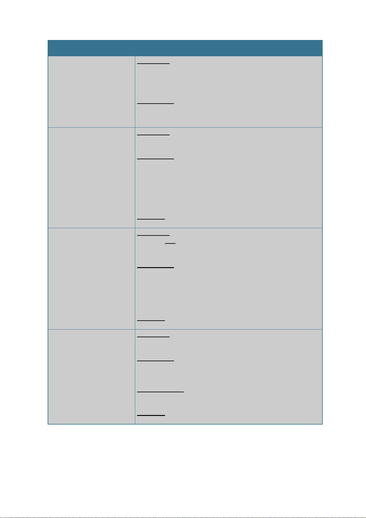
Application
Description
System Check
with Radiated Field
Procedure: the well-defined field generated by the RefRad X
Field Source is measured with the EMC/EMF measurement
system. This measurement is done once with a well-checked setup
as reference and it is repeated before each measurement
campaign. A comparison between the reference and the actual
system check ensures the quality of the results.
Advantages:
convenient detection of defects in the receiving system
suitable for all antennas
suitable for GTEM and other micro cells
Considerations:
influenced by the test environment (EMF)
influenced by the EUT (EMC)
coupling to the receive cable hinders fault detection
positioning can be critical
System Check
with Antenna Coupler
Procedure: the well-defined field generated by the antenna
coupler connected to the RefRad X Comb Generator is measured
with the EMC/EMF measurement system. Same procedure as
System Check with Radiated Field.
Advantages:
not influenced by the test environment (EMF)
not influenced by the EUT (EMC)
reliable detection of defects in the receiving system
easy and precise positioning for high repeatability
Considerations:
individual coupler required for each antenna
System Check
with LISN Coupler
Procedure: check of conducted emission test setup using the
RefRad X Comb Generator and the LISN coupler. Same
procedure as System Check with Radiated Field.
Advantages:
reliable detection of defects in the measurement system
easy and precise operation
Considerations:
individual coupler required for each LISN type
SEIBERSDORF LABORATORIES REFRAD X MANUAL |
7
Application
Description
Coaxial System Check
Procedure: check of coaxial section of conducted or radiated
emission test setup using the RefRad X Comb Generator and the
protective attenuator. Same procedure as System Check with
Radiated Field.
Advantages:
reliable identification of the fault source
easy and precise operation
Normalized Site Attenuation
Measurement,
Semi Anechoic Chamber
Procedure: the RefRad X Comb Generator is used as a signal
generator in the normalized site attenuation measurement [1,2].
Advantages:
high measurement speed with modern EMI receiver
high output power guarantees a good signal-to-noise ratio
the FibreLink X can be used to increase the dynamic range
by up to 30 dB
battery powered operation avoids metallic cables in the
test volume
Software: CalStan 10.0, NSA SAC module recommended
Normalized Site Attenuation
Measurement,
Fully Anechoic Room
Procedure: the RefRad X Field Source is used as a signal
generator and transmit antenna in the normalized site attenuation
measurement [1]
Advantages:
ideal radiation characteristic, no metallic feed cable
high measurement speed with modern EMI receiver
high output power guarantees a good signal-to-noise ratio
the FibreLink X can be used to increase the dynamic range
by up to 30 dB
Software: CalStan 10.0, NSA FAR module recommended
Cable Loss Measurement
Procedure: the RefRad X Comb Generator with the protective
attenuator is used as signal generator.
Advantages:
convenient measurement of installed cables
high measurement speed with modern EMI receiver
Considerations:
overload of receiver possible when no attenuator is used
Software: CalStan 10.0, cable loss module recommended

| REFRAD X MANUAL SEIBERSDORF LABORATORIES
8
Application
Description
Field Strength Transfer
Procedure: the RefRad X Field Source is used as signal
generator and transmit antenna to compare the site attenuation of
different test site types. The field strength generated is measured
on the calibration site (e.g. Open Area Test Site) and then in the
GTEM cell. The difference is the calibration factor of the cell.
Advantages:
calibration of TEM and GTEM cells
no metallic feed cable –no field disturbance
high measurement speed with modern EMI receiver
high output power guarantees a good signal-to-noise ratio
the FibreLink X can be used to increase the dynamic range
by up to 30 dB
Considerations:
overload of receiver possible when no attenuator is used
Shielding Attenuation
Measurement
Procedure: the RefRad X Field Source, Sync Mode is used as
signal generator and transmit antenna to investigate the shielding
attenuation of enclosures.
Advantages:
optical fibre does not degrade shielding performance
high output power guarantees a good signal-to-noise ratio

SEIBERSDORF LABORATORIES REFRAD X MANUAL |
9
3. CONTENT OF SETS
Table 1 shows the three measurement sets and their components.
RefRad X Set1
Field Source Set 2
Field Source Set,
Sync Mode 3
RefRad X Comb
Generator
Charger
Protective
Attenuator
Conical Antenna
Element
H-Holder
Transport Case
FibreLink X
Optical Fibre
Cable and
Connector
Table 1: Contents of different RefRad X sets
1
Set RR 4 in price list
2
Set RR 5 in price list
3
Set RR 6 in price list

| REFRAD X MANUAL SEIBERSDORF LABORATORIES
10
3.1. Accessories
Table 2 shows the accessories available for the RefRad X and their suitability for the different sets offered.
RefRad X Set
Field Source Set
Field Source Set,
Sync Mode
LISN Coupler
Antenna Coupler
Optical Fibre Cable
30m
Software
CalStan 10.0
Table 2: Accessories for RefRad X sets

SEIBERSDORF LABORATORIES REFRAD X MANUAL |
11
3.2. RefRad X Set (RO 10)
Figure 1: Contents of the RefRad X Set
3.3. Field Source Set (RR 5)
Figure 2: Contents of the Field Source Set
Charger
RefRad X
20 dB Attenuator
Transport Case
Conical Antenna Element
RefRad X
20 dB Attenuator
Charger
H-Holder and Screw

| REFRAD X MANUAL SEIBERSDORF LABORATORIES
12
3.4. Field Source Set, Sync Mode (RR 6)
Figure 3: Contents of the Field Source Set, Sync Mode
Transport Case
FibreLink X
RefRad X, Field Source
20 dB Attenuator
Optical Fibre Cables
Charger
H-Holder and Screw
Fibre Connector

SEIBERSDORF LABORATORIES REFRAD X MANUAL |
13
4. DESCRIPTION OF THE REFRAD X SYSTEM COMPONENTS AND
ACCESSORIES
For electromagnetic compatibility (EMC) and electromagnetic field (EMF) testing it is important to validate
the radiated and conducted measurements on a regular basis for quality assurance reasons. The modular
concept, the selectable line spacing and the ultra-wide frequency range make the RefRad X to a one box
solution for much more flexibility in EMC and EMF testing.
RefRad X can be used as a classical comb generator for all kinds of coaxial measurements and
measurements with an antenna or LISN coupler (see Chapter 2). With the conical antenna element attached,
it transforms into a field source (patented) - an antenna with built-in comb generator (see Figure 4)
Coaxial Mode Transformation Field Source Mode
Figure 4: Schematic of the RefRad X comb generator
(left) for coaxial measurements via the N-connector and the transformation (centre)
to the RefRad X field source (right) using the conical antenna element
.
Conical
antenna
element
RefRad X
field source
N(f) connector
RefRad X
comb generator
| REFRAD X MANUAL SEIBERSDORF LABORATORIES
14
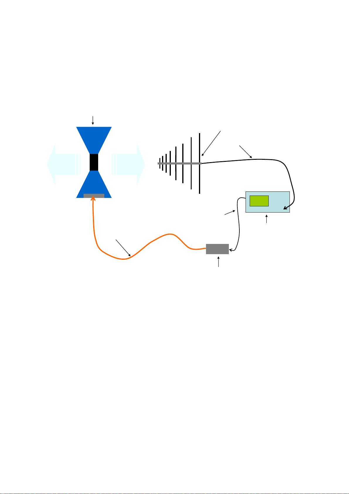
The FibreLink X increases the measurement dynamic (e.g. for shielding efficiency tests) by synchronizing
the comb generator with the receiver. See Figure 5 for a schematic of the test setup.
Figure 5: Schematic of the RefRad X operated in field source mode
with FibreLink X for Sync Mode measurements
RefRad X
field source
Optical fibre
Receive antenna
RF-cable
FibreLink X
Receiver
10 MHz receiver
reference frequency
SEIBERSDORF LABORATORIES REFRAD X MANUAL |
15
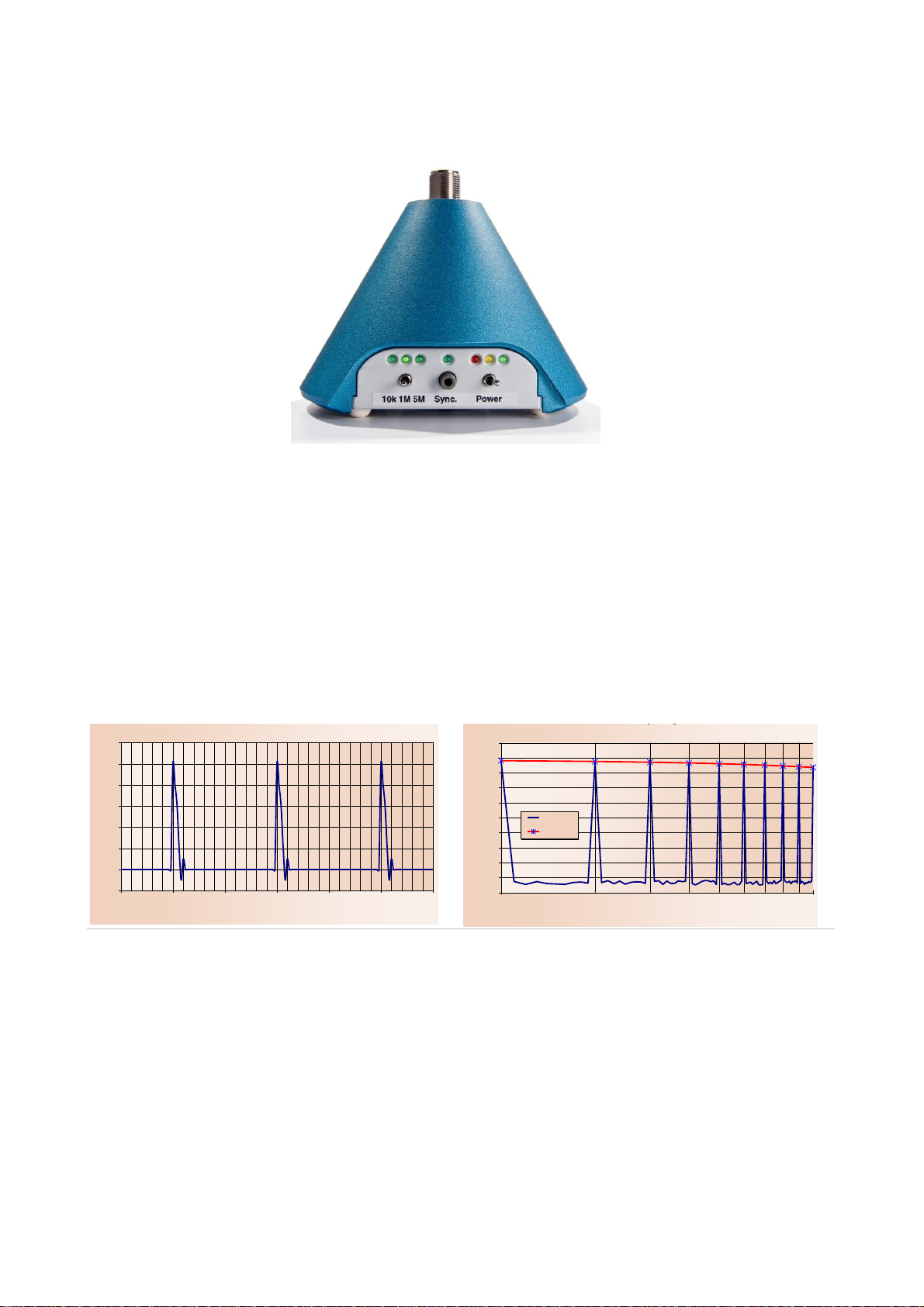
4.1. RefRad X Comb Generator
Figure 6: RefRad X
4.1.1. Description
The comb generator RefRad X (see Figure 6) produces pulses with a repetition rate of 100 µs, 1 µs or
200 ns in time domain. These pulses represent a comb spectrum with a line spacing of 10 kHz, 1 MHz or
5 MHz in frequency domain. All frequency lines are present at the same time (see Figure 7) therefore no
remote control between the comb generator and the receiver is required.
RefRad 3000, Time Domain
-2
0
2
4
6
8
10
12
0.5 1 1.5 2 2.5 3 3.5
Time [µs]
Voltage [V]
RefRad 3000, Frequency Domain
-100
-90
-80
-70
-60
-50
-40
-30
-20
-10
0
110
Frequency [MHz]
Level [dBm]
Level
Envelope
Figure 7: The RefRad X comb generator pulses in time domain (left) and in frequency
domain (right), 1 MHz spectrum

| REFRAD X MANUAL SEIBERSDORF LABORATORIES
16
Like all comb generators, RefRad X uses a built-in crystal oscillator with limited accuracy. The settings on
the measurement instrument (e.g. receiver) have to be made with consideration of this effect by using a
proper resolution bandwidth which is larger than the frequency error (e.g. 100 kHz) and as low as possible
for getting a good signal-to-noise ratio.
To improve the frequency accuracy, RefRad X is equipped with a synchronisation circuit used to connect an
external 10 MHz reference signal via optical fibre: FibreLink X. By synchronizing the RefRad X with the test
receiver measurements with the lowest resolution bandwidth, the dynamic range is increased by up to 30 dB.
A resistive 50 Ω matching network is provided between the pulse generator and the output for matching
purposes.
The RefRad X comb generator is not designed to be operated using the battery charger as a power source.
4.1.2. Technical Specifications
Technical Specifications
Frequency range
10 kHz –3 GHz
Frequency spacing
10 kHz, 1 MHz, 5 MHz
Frequency stability (internal)
25 ppm -45°C - +80°C
(25 Hz at 1 MHz, 75 kHz at 3 GHz)
Amplitude per line (coaxial)
See Figure 8
Amplitude stability
± 0.2 dB, battery voltage cycle
± 0.5 dB, temperature range 0°C - 40°C
Batteries
internal, NiMH (factory serviceable only)
Battery operation time
12 hours (10 kHz), 8 hours (1 MHz), 6 hours (5 MHz)
Low battery warning
Yellow LED - recharge recommended
Red LED - recharge
RF-output connector
N-female
Optical input connector
ST-female
Tripod thread
1/4"
Climatic operation conditions
Temperature: 10 –40 °C
Humidity: 30 –80%
avoid humidity and rain
Dimension of RefRad X
134 mm x 110 mm
Weight of RefRad X
0.955 kg
Table 3: Technical specifications of RefRad X Comb Generator
SEIBERSDORF LABORATORIES REFRAD X MANUAL |
17
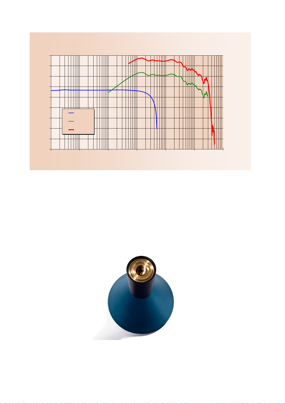
Figure 8: Typical coaxial output for all three line spacings
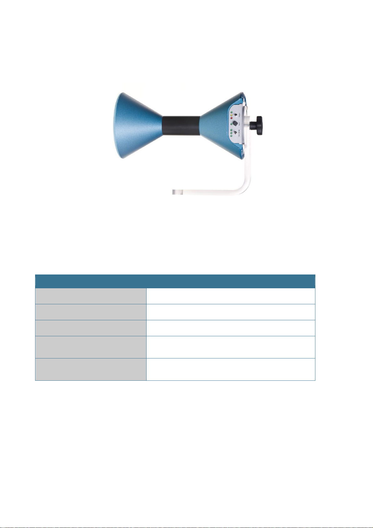
4.2. Conical Antenna Element
Figure 9: Conical Antenna Element
RefRad X, coaxial output
-90
-80
-70
-60
-50
-40
-30
-20
-10
0
0.01 0.1 1 10 100 1000 10000
Frequenz [MHz]
Output Power [dBm]
10 kHz
1 MHz
5 MHz
| REFRAD X MANUAL SEIBERSDORF LABORATORIES
18
4.2.1. Description
To operate the RefRad X in field source mode, the conical antenna element (Figure 9) must be connected to
the coaxial RF-output of the comb generator (see Figure 10).
Figure 10:RefRad X in field source mode, mounted on the H-Holder in horizontal polarisation
4.2.2. Technical Specifications
Technical Specifications
Frequency range
30 MHz –1 GHz
Field strength
See Figure 11 to Figure 12
Radiation pattern
See Figure 13
Dimension of RefRad X with conical
antenna element
134 mm x 255 mm
Weight of RefRad X with conical
antenna element
1.405 kg
Table 4: Technical specifications of the conical antenna element
Table of contents
Popular Laboratory Equipment manuals by other brands

VWR
VWR INCU-Line IL 56 Short instruction manual

Barnstead International
Barnstead International Cimarec series Operation manual and parts list

Biobase
Biobase BK-HS32 user manual

SYSMEX
SYSMEX ogt Cytocell Multiprobe OctoChrome Instructions for use

VWR
VWR avantor 442-1266 instruction manual

IAI
IAI SW-4000T-10GE user manual


