Sherwood Scientific
860 89 001 Issue 1 22nd September 2008 ECN 536 10
3.2 Operating Sequences
At Power On
When the instrument is first switched on it will perform a self test. The first check is for the
presence of the Safety Cover. A Hall sensor mounted on the Switch PCB inside the top of
the Tower checks for the magnetic field from the magnet in the top right-hand edge of the
Safety Cover. If the magnet cannot be detected the instrument will not progress any
further and an error is indicated by a flashing ‘Status’ LED. To adjust the sensor, follow
the instructions in Section 4.5.
The next check is for the correct starting position of the Carriage. The Carriage will make
small movements up and down aligning the Hall sensor mounted on the back of the
Carriage PCB with the magnet mounted at the top of the Motor Plate. If the magnet
cannot be detected an error is indicated by the ‘Sampling’ LED illuminating. To adjust the
sensor, follow the instructions in Section 4.6.
Assuming the Carousel is near its correct position, it will make small side to side
movements. Unless it is grossly out of position in which case it will motor round to the
start position. The Hall sensor mounted on the Tower Base is looking for the magnetic
field from the magnet on the underside of the Carousel. If the magnet cannot be detected
then an error is indicated by the ‘Ready’ LED illuminating and the ‘Status’ LED flashing.
Should the gap in the Carousel not be central about the Sample Probe, adjust the Sensor
position as described in Section 4.2.
Finally the motor will run to pull the Probe Carrier in towards the body of the instrument,
its start position.
The ‘Ready’ LED will illuminate to indicate a successful initialisation.
After pressing Run
The Carriage will make small up and down movements followed by the Probe Carrier
being pulled inwards, then the Carousel will move side to side.
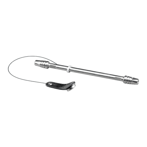
Once a measurement is initiated the Carriage moves down and the Bottle Sense Shaft is
displaced, moving its magnet away from the Hall Sensor. If this does not happen an error
is indicated by the ‘Sampling’ LED illuminating. For details on adjusting the height of the
Bottle Sense Shaft refer to Section 4.4.
After each measurement when the Carriage lifts the Sample Probe out of a vial, the
instrument checks for the Hall sensor to be triggered by the magnet at the top of the
movement to ensure the Probe and Bottle Sensor are clear of the vials before allowing
the Carousel to rotate.
After pressing Stop
The Carriage will move up to clear the sample vials, the Carousel will rotate to the start
position and the Probe Carrier will be pulled in.


