Astra Navsensor NMEA 2000 User manual

NMEA 2000
Navsensor
User Manual

2

3
Contents
ASTRA Navsensor 4
Preliminary Remarks 4
Safety Instructions for Installation 4
Safety Instructions for Maintenance 6
The ASTRA Navsensor 7
Components 7
Functions 7
The NMEA Interface 8
Installation of the ASTRA Navsensor 10
Flat mount installation 11
Pole mount installation 13
Calibration 14
Diagnostic Indication 17
Hardware Specification 18
Brackets 18
Pinout 18
Technical Data 19
Accessories 21

4
ASTRA
Navsensor
Preliminary Remarks
In purchasing a sensor from the ASTRA marine range you have decided on a
high value product, which has been manufactured according to acknowledged
technical standards. Modern production processes and compliance with
currently applicable quality assurance standards guarantee that our products
leave the factory in perfect condition.
We thank you for making a good choice, and we are convinced that this
instrument will be reliable and of great help to you and keep you safe at sea.
In order to ensure easy and safe handling of your ASTRA sensor, you should
familiarize yourself with all the features and functions.
Please take the time to read these instructions carefully and completely.
Safety Instructions for Installation
This product has been developed, manufactured and tested in accordance
with the requirements of EC, UL and FCC directives and the acknowledged
state of the art.
Please follow all the instructions given in this handbook exactly.
Please pay attention to all text passages labeled with this symbol. These are
very important hints for operating and security of the instruments.

5
Before beginning work the native terminal of the battery
should be disconnected.
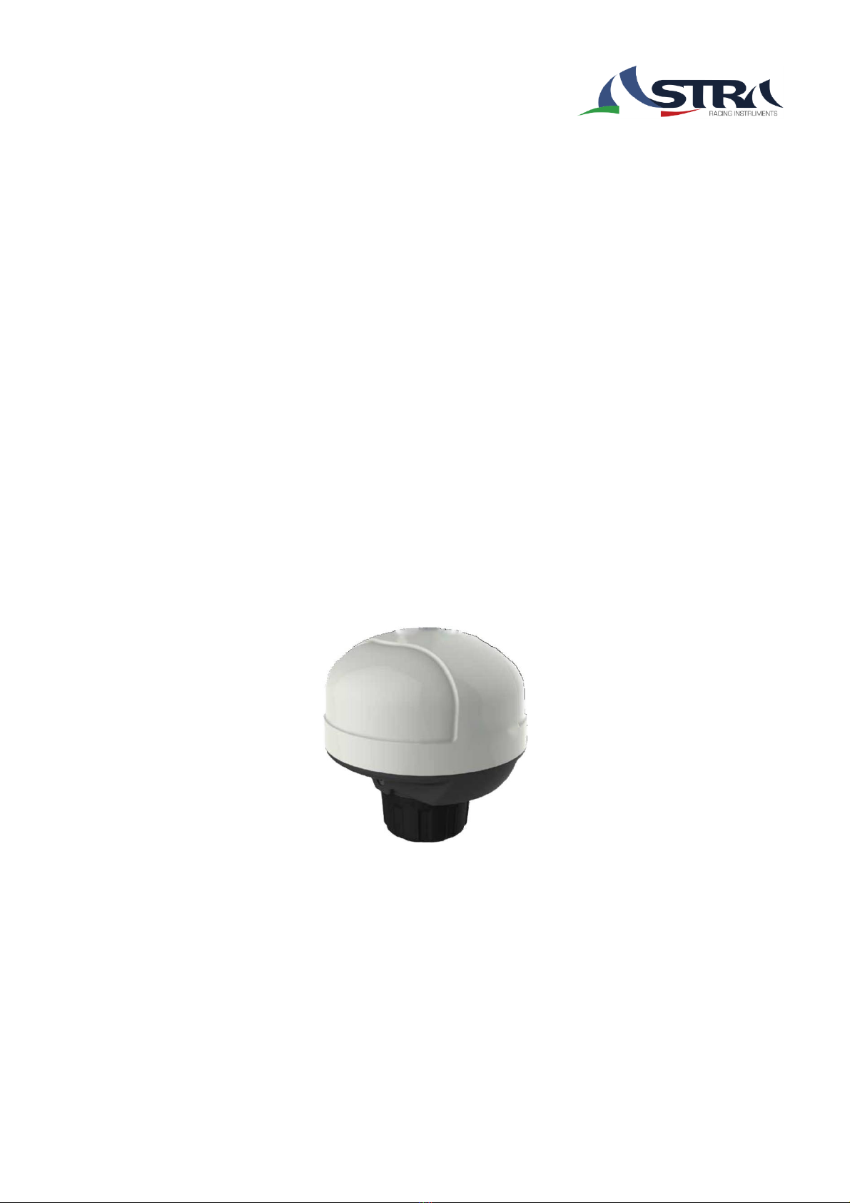
Use of information provided by the ASTRA Navsensor does not release
you from the responsibility over your ship and demands good seamanship.
Always use your nautical experience in interpreting the displayed values.
If you carry out this work yourself, wear suitable working clothes. Do not
wear wide fitting clothes. If you have long hair, wear a hair-net. Clothes
and hair can get caught in moving and rotating parts.
Wearing of metallic or conductive jewellery, such as necklaces, bracelets,
rings etc. is not allowed when working on the electrical installation on
board.
Please note that with disconnection of the battery, all volatile electronic
memories lose their input values and must be reprogrammed.
Explosion hazard! Before beginning work on the engine
compartment of petrol engines, switch on the ventilator
of the engine compartment.
Ensure that necessary clearance is provided behind the cable opening, at
the position where the sensor is to be installed.
When selecting the installation position for the sensor, take care that no
stringers are drilled. Be careful also of furniture, floorboards,
superstructure boxes, cables etc.
When carrying out installation work with a sealing compound, solvent
vapours can be formed. Make sure of adequate ventilation and follow the
instructions for use of the sealing compound manufacturer.

6
For the installation only use ASTRA or NMEA approved cables.
If you don’t use standard cables, the wires used should be adequately
insulated or should have sufficient electrical strength, and the contact point
should be protected against electrical shock hazard. The electrical conducting
components of the connected consuming devices should also be protected
against direct contact through suitable measures. Installation of bare metallic
wires and contacts is not allowed.
Take account of the wire cross section. A reduction of the wire cross section
results in a higher current density. This can cause the wire to heat up and
potentially catch fire.
Connect the wires only in accordance to the wiring diagram.
Safety Instructions for Maintenance
The sensor display unit is maintenance-free. Do not use cleaning agents.
Repairs on the sensor should be carried out only by ASTRA authorized
specialists

7
The ASTRA Navsensor
The multifunctional ASTRA Navsensor is the gem of all sensors. The
inertial sensor complements the inbuilt satellite receiver module (GPS)
to provide accurate readings of the speed of travel as well as the pitch &
roll (up and down) and YAW (sideways) motion of the boat. Compass
readings can be displayed electronically thanks to the fluxgate, which
also facilitate course corrections in electronic autopilots.
The barometer and air temperature sensors are early indicators of
forthcoming weather conditions.
Components
In the box:
- Navsensor
- Flat mount bracket
- Pole mount bracket
- Installation instruction
- Mounting screws (not magnetic)
- Warning Sticker
Functions
The sensor provides following information via NMEA 2000:
- GPS-Position
- Date/Time (UTC)
- Speed over Ground

8
- Course over Ground
- Elevation
- Heading
- Barometric Pressure
- Air Temperature
- Rate of Turn
- Pitch and Roll
The NMEA Interface
The ASTRA Navsensor is a NMEA certified sensor. It transmits and receives
NMEA 2000 data to an existing NMEA 2000 network
The parameter group numbers (PGN) of the data which the sensor sends are
given in the table below. More information about NMEA can be found under
www.nmea.org
Receiving PGNs
PGN
Message name
59392
Acknowledgment ISO
60928
Address Claim ISO
126208
Command Group Function
59904
Request ISO
60160
Transport Protocol, Data Transfer ISO
60416
Transport Protocol ISO

9
Transmitting PGNs
PGN
Message name
59392
Acknowledgment ISO
60928
Address Claim ISO
65240
Commanded Address ISO
126208
Command Group Function
126464
TX/RX PGN List Group Function
126993
Heartbeat PGN
126996
Product Information
126998
Configuration Information
127250
Vessel Heading
127251
Rate of Turn
127257
Attitude
129025
Position, Rapid Update
129026
COG & SOG, Rapid Update
129029
GNSS Position Data
129033
Local Time Offset
130311
Environmental Parameters
130314
Actual Pressure
130316
Temperature, Extended Range
127258
Temperature (Old Version)

10
Installation of the ASTRA Navsensor
Before beginning, disconnect the negative terminal on the battery, otherwise
you risk a short circuit. If the craft is supplied by auxiliary batteries, you must
also disconnect the negative terminals on these batteries! Short circuits can
cause fires, battery explosions and damages to other electronic systems.
Please note that when you disconnect the battery, all volatile electronic
memories lose their input values and must be reprogrammed.
Where to install
Mount the Navsensor at least 1m away from VHF antennas and
clear of radar arrays
Mount the sensor as midship as possible and with clear sky view
Note: If installed on steel hull vessels, install the sensor as high as possible
away from the magnetic steel.

11
Warning Label
Please place the included warning sticker near the installation location
Flat mount installation
Warning
DO NOT attach a Navsensor where it can cause a person to fall down or
where a person can accidentally hit it with their foot and cause damage to
the device.
Warning
Always put a grommet in a hole made for cable access.
Use the mounting bracket to give the locations of the four stainless steel
non magnetic screws:

12
1. Put the mounting bracket (3) on the vessel where you are to at-
tach it. Make sure that you will not cause damage to other equipment,
ropes or electrical cables when you attach the bracket.
2. Use the mounting template to mark the position of the four attach-
ment holes. Examine the location again to make sure that it is a good
location, then drill 4 x 3.5 mm holes.
Note: If screws are to attach the bracket to wood, drill 1.5 mm pilot holes and
not 3.5 mm clearance holes.
3. Use two screws to temporarily attach the bracket to the vessel.
4. Put a 15 mm dia. drill bit into the centre of the mounting bracket
and drill a cable access hole into the vessel. Remove the two attach-
ment screws and bracket. Deburr all holes and clean them fully.
5. Put a 15 x 6 mm grommet on to a NMEA 2000 micro cable (Not
supplied). Carefully push the cable through the hole and set the grom-
met in this hole.
6. Push the NMEA 2000 micro cable through a bracket gasket (if
used) and then the bracket. Align the bracket to its attachment holes
in the vessel.
7. Use the not magnetic stainless steel screws to attach the bracket
to the vessel.
Do not cause damage to the cable or surface of the vessel.
8. Align the keyway in the cable connectors and then push the NMEA
cable into the socket in the bottom of the Navsensor (1).
Turn the collar to lock the cable
9. Make sure that the arrow on the bottom of the sensor is aligned
with the vessel’s keel
10. Put the Nav sensor on to the bracket. Carefully push the cable
through the grommet in the access hole while you do this.
11.Tighten the set screw (2) (3 mm hex key).
12. Get the free end of the NMEA 2000 micro cable and connect it to
a T-junction of a existing NMEA 2000 backbone.
Note: Make sure that you set the cable away from sources of Electrical
Magnetic interference. Also make sure that the foot of a person cannot touch
the cable and cause injury to the person or cause damage to the cable.

13
Pole mount installation
Warning
Always put a grommet in a hole made for cable access.
Attach the Navsensor housing to a pre-installed threaded pole:
1. Turn the mounting collar (3) fully on to the pole. Maximum
torque to use is 12 Nm. This pole must have an external thread
1-14 UNS-2A.
2. Push the NMEA 2000 micro cable through the mounting collar
and pole.

14
Note: Be careful when you move the cable. Make sure that no sharp
edges can cause damage to the cable insulation.
3. Align the keyway in the cable connectors and then push the NMEA
cable into the socket in the bottom of the Navsensor (1).
Turn the collar to lock the cable.
4. Carefully push the cable through the mounting pole, put the
Navsensor on to the mounting collar and align the arrow on the bot-
tom of the sensor with the vessel’s keel
5.Tighten set screw (2) (3 mm hex key).
Do not cause damage to the cable or surface of the vessel.
6. Get the free end of the NMEA 2000 micro cable and connect it to
a T-junction of a existing NMEA 2000 backbone.
Calibration
The Navsensor comes along with a built in fluxgate compass, able to calibrate
itself to the influence of magnetic components of the vessel. Since this
interferce may change over time, the calibration should be performed from
time to time.
The compass calibration routine should be executed:
- after the installation of the NavSensor
- before long voyages
- after installation of new electronic components
- after welding work
- at least once a year (at beginning of the season)
The calibration is performed by turning the boat for two full circles. To get the
best accuracy please be aware of the following conditions:

15
- The circle diameter should have
about 4 to 6 times the length of the
hull
- The circles should be as round as
possible
- The speed of the boat should be
around 2-3kn.
- The maneuver should be carried out
away from boat traffic, large ships and
harbor installations
- The weather conditions should
be calm (low wave height and wind
speed)
Please execute following steps:
1. Start turning the boat in a clock-
wise direction and then press the
push button on the Navsensor for
5 seconds (the color turns from
green to steady red)
2. Continue turning the boat untill the
red color of the button goes back to
grey (approx. after 1 1/5 circles)
3. Start turning the boat counter
clockwise and press the button again
for 2 seconds (the color turns back to
steady red) any issues please refer
to the LED code list below.
4. Continue turning the boat until the
steady red color changes.
Setting push button
with integrated
LED
Note: During this process there is no compass reading present!
5. At the end of the second circle the NavSensor analysis the data of both
circles. If the result doesn’t differ more than 2° the new compensation
values will be used and the compass is calibrated successfully. In this
case the color changes to green ( steady or flashing)

16
If the data differs by more than 3° the new reading will not be used. In this
case the color turns to red (flashing). Please repower the sensor and re-do the
calibration.
An unsuccessful calibration can be caused by:
- Bad weather conditions (too high waves and/or strong wind)
- Not the right speed or circle distance performed
- Moving magnetic components close to the sensor
- Electronic equipment close to the sensor
- Inproper positioning of the sensor
Note: Red flashing can also be caused by a different internal failure of the
NavSensor. Please refer to chapter “Diagnostic Indication”
Note: After the first successful installation and calibration general aligment
of the Navsensor in respect to the fore and aft line of the boat should be
checked. This is done by performing several plottings to different landmarks
(please take magnetic variation into account as well). If there is a deviation in
the alignment the sensor should be turned on its bracket accordingly (if so, an
additional sensor calibration has to be performed afterwards).

Diagnostic Indication
17
LED color
LED Status
Comment
Green
steady lit
Everything is working ok
Green
1 Hz flashing
Compass is working ok; GPS has no satellite
reception
Red
steady lit
Compass calibration circle is performed
Off
Compass calibration first circle iscompleted or
power fail
Red/
Green
1 Hz flashing
Supply voltage too low (below 9V)
Red
1 Hz flashing
Possible root causes:
External failures:
- Over voltage (above 30V)
- NMEA 2000 network problems (e.g. missing
terminator)
Internal failures:
- Memory lost
- GPS sensor communication failed
- Compass electronic failure
- Acceleration or gyro sensor communication
failed
- Barometer module communication failed
Other failures:
- Compass calibration failed (not accurate)

18
Hardware Specification
Sensor
Brackets
Flat Mount:
Pole Mount:
Pinout
Pin Signal
1 Shield
2 NET-S (V+)
3 NET-C (V-)
4 NET-H (CAN H)
5 NET-L (CAN L)

19
Technical Data
Housing Material
Mounting/Housing: Plastic (PBT-ASA-
GF30FR)
Top: Plastic (ASA)
Dimensions
WxH: 100 x 108.3 mm
In-/Outputs
See “In-/Output Table” below
Unit weight
250g
Operating temperature
-20° / +70°
Storage temperature
-30° / +80°
Operating voltage range
8 –16 VDC
Current consumption
~50mA
GPS channels
66 channels (22 Tracking, 66 Acquisi-
tion)
GPS datum
WGS-84 (default)
GPS-time to first fix
Cold (open sky): 33s (typical)
Warm (open sky): 1s (typical)
GPS frequency range
1575.42MHz ± 1.023MHz
GPS position accuracy
GPS max. altitude
Autonomous: 3m (2D RMS)
< 50,000 m
GPS max. velocity
< 515 m/s
Air temperature range
-20° / +65°C
Air temperature accuracy
+/-1°C
Air temperature adaption time
30s
Barometer resolution
1hPa
Yaw resolution
1°/s
Yaw range
+/- 100°/s
Yaw zero error
+/- 0.7°/s
Calculated heeling resolution
1°
Calculated heeling, pitch & roll-range
+ / -50°
Compass resolution
0.5°
Compass accuracy
>10uT
Compass field strength
min 8 –80 uT
Compass tilt angle
+ / - 40°
Compass auto calibration
by 2 circles (opposite directions)

20
Nominal Position
NL 0; According to DIN 16257
Mounting/Fixing
Top or pole mount; Thread: 1-14 UNS-
2B
Protection Class
IP 65
According to IEC 60529:2001;
in nominal position
Flammability Housing
UL-94 V0
EMC
DIN-EN 61000-6-2:2006
IEC 60945:2002
DIN-EN 61000-6-3:2011
Reverse Polarity Protection
Yes, 1 minute
Short Circuit Protection
Yes, 1 minute
NMEA manufacture code
443
NMEA product code
8600
Approval
CE, NMEA 2000 V2.0
ASTRA product number (packed)
A2C59501981
ASTRA product number (unpacked)
A2C96792000
Table of contents