manuals.online logo
Brands
  1. Home
  2. •
  3. Brands
  4. •
  5. Grizzly
  6. •
  7. Accessories
  8. •
  9. Grizzly H8371 User manual

Grizzly H8371 User manual

Specifications
Motor ................................................. 110V 60Hz
Speed ............................................... 4–160 RPM
Maximum Torque .................................650 in./lb.
Inventory
Refer to Figure 1 and the table below to inventory
the contents of the shipping box.
MODEL H8371
POWER FEED
FOR KNEE MILLS
INSTRUCTIONS




Figure 1. Model H8371 inventory.
COPYRIGHT © MARCH, 2008 BY GRIZZLY INDUSTRIAL, INC.
WARNING: NO PORTION OF THIS MANUAL MAY BE REPRODUCED IN ANY SHAPE
OR FORM WITHOUT THE WRITTEN APPROVAL OF GRIZZLY INDUSTRIAL, INC.
#TS10534 PRINTED IN TAIWAN
Bolt Bag Inventory Qty
Spacer Set 34mm .............................................. 1
Spacer Set 16mm .............................................. 1
Bushing Spacer ................................................. 1
Slotted Flat Washer ........................................... 1
Special Hex Nut 1⁄2"-20 ...................................... 1
Cap Screws 1⁄4"-20 x 1" ..................................... 2
Roll Pins 5.1 x 14mm ........................................ 2
Phillips Head Screws #10-24 x 3⁄8" .................... 2
Flat Washers 5mm ............................................ 2
Cable Clamps .................................................... 2
Tie Wraps .......................................................... 2
If any nonproprietary parts are missing (e.g. a
washer or a spacer), we will gladly replace them;
or for the sake of expediency, replacements can
be obtained at your local hardware store.
If you need help with your new power feed, call
our Tech Support at: (570) 546-9663.
REF PART # DESCRIPTION
1 PH8371001 MOUNTING BRACKET
2 PH8371002 POWER FEED & LIMIT SWITCH ASSY
3 PH8371003 COMPLETE BOLT BAG
4 PH8371004 LIMIT STOP ASSEMBLY
5 PH8371005 BEVEL GEAR BRASS
Be sure there is enough running clearance
between the table, spindle, vise/clamps, or
jigs before turning the power feed ON. Be
aware that all of these objects represent
potential pinch points.
-2- H8371 Power Feed for Knee Mills






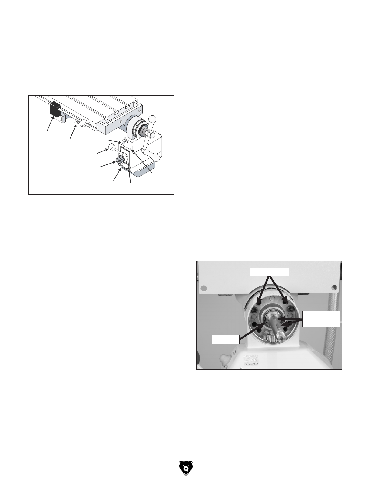
Figure 2. Power feed system.
A. Limit Switch: Stops powered table move-
ment when either limit stop presses a plunger
on the switch.
B. Limit Stop: Activates the limit switch. Secure
these devices along the table to set the range
of movement.
C. Rapid Movement Button: Moves the table
at the maximum speed in the direction select-
ed.
D. Direction Lever: Starts, reverses, and stops
longitudinal table movement.
E. Speed Dial: Controls the speed that the table
moves—turn the dial clockwise to increase
the speed.
F. Reset Button: When a current over 3.5
amps passes through the unit for more than
10 seconds, the internal circuit switch will cut
the power to the unit. Investigate and resolve
any problems, then use this button to reset
the internal circuit switch.
G. ON/OFF Switch: The master power switch
for the power feed.
H. Power Lamp: Lights when the power feed is
turned ON.
Functional Overview
The Model H8371 power feed is designed to
install on the right side of a knee mill table to pro-
vide powered longitudinal movement of the table.
Refer to Figure 2 and the descriptions below to
become familiar with the functional parts of the
power feed system.
Installation
1. DISCONNECT THE MILL FROM POWER!
Note: During the next step, take care not to
misplace the leadscrew keys.
2. Remove the handle and graduated dial
assemblies from the right side of the longitu-
dinal (X-axis) leadscrew.
3. Determine if there is adequate support on
the mill to mount the power feed unit onto the
leadscrew.
— If adequate mounting for the power feed
unit exists at the end of the leadscrew, you
do not need to use the optional mounting
bracket. Continue with Step 4.
— If there is not adequate mounting for the
power feed unit, you will need to use the
provided mounting bracket. Proceed to
Using the Mounting Bracket on Page 4.
4. Make sure the leadscrew is clean of debris
and oil, then slide the power feed unit onto
the leadscrew and up against the mill, as
shown in Figure 3.
Figure 3. Power feed unit mounted on the
leadscrew.
Spacers
Leadscrew
Keys
Cap Screws
Note: Use the spacers provided where nec-
essary to ensure that the parts installed on
the leadscrew stay snug up against one
another.
H8371 Power Feed for Knee Mills -3-
5. Secure the power feed unit to the mill with the
cap screws.
Note: If the threaded holes in the mill do not
align with the holes provided in the power
feed unit, drill and tap holes in the mill as
necessary to properly secure the unit to the
mill.
6. Install the keys onto the leadscrew.
7. Remove the plastic protective cap from the
brass bevel gear, align the keyway in the
gear with the leadscrew keys, then slide the
gear onto the leadscrew and up against the
power feed unit (see Figure 4).
Note: Make sure that the teeth of the bevel
gear and drive gear mesh properly.
Figure 4. Brass bevel gear installed onto the
leadscrew.
Brass
Bevel
Gear
8. Re-install the graduated dial and handle
assemblies.
Electrocution or fire could
result if machine is not
grounded and installed in
compliance with electrical
codes. Compliance MUST
be verified by a qualified
electrician!
10. Position and mount the limit switch in the
center of the saddle, as shown in Figure 5,
so that the plungers on the sides of the unit
align with the limit stops.
11. Make sure the ON/OFF switch is in the OFF
position, then connect the power feed unit to
a grounded 110V power source.
Figure 5. Example of limit switch and limit stops
installed.
Limit Switch
Limit Stops
9. Slide the T-nuts of the limit stops into the
front slot of the table (see Figure 5), position
them to limit the range of table movement,
then tighten the hex bolts to secure them in
place.
-4- H8371 Power Feed for Knee Mills
Using the Mounting Bracket
1. Use the roll pins and cap screws to install the
power feed unit onto the mounting bracket
(see Figure 6).
Figure 7. Example of power feed unit installed
with the mounting bracket.
Mounting Bracket
Figure 6. Mounting bracket.
Roll Pins
Mounting Bracket
2. Make sure the leadscrew is clean of debris
and oil, then slide the assembly onto the
leadscrew to mark the points needed to drill
and tap holes for mounting screws in the side
of the table.
Note: Use the spacers provided where nec-
essary to ensure that the parts installed on
the leadscrew stay snug up against one
another.
3. Remove the assembly, drill and tap the
mounting holes, re-install the power feed
assembly onto the leadscrew, then secure the
mounting bracket to the table (see Figure 7.
Maintenance
Clean and lubricate the power feed gearing every
three months of normal use.
To clean and lubricate the power feed gear-
ing:
1. DISCONNECT THE MILL AND POWER
FEED FROM POWER!
2. Remove the handle and graduated dial
assemblies.
3. Slide the brass bevel gear from the lead-
screw, then remove the leadscrew keys.
4. Clean the debris and built-up grime from the
leadscrew and the gearing.
5. Brush a light coat of all-purpose grease onto
the teeth of the bevel and drive gears.
6. Re-install the parts removed in reverse
order.
4. Continue with Step 6 on Page 3.

Other Grizzly Accessories manuals

Grizzly G8987 User manual

Grizzly

Grizzly G8987 User manual

Grizzly G0577 User manual

Grizzly

Grizzly G0577 User manual

Grizzly H8165 User manual

Grizzly

Grizzly H8165 User manual

Grizzly G7028 User manual

Grizzly

Grizzly G7028 User manual

Grizzly H0775 User manual

Grizzly

Grizzly H0775 User manual

Grizzly G1822 User manual

Grizzly

Grizzly G1822 User manual

Grizzly G0750G User manual

Grizzly

Grizzly G0750G User manual

Grizzly G1026 User manual

Grizzly

Grizzly G1026 User manual

Grizzly G1763 User manual

Grizzly

Grizzly G1763 User manual

Grizzly G0708 User manual

Grizzly

Grizzly G0708 User manual

Grizzly G4816 User manual

Grizzly

Grizzly G4816 User manual

Grizzly T10113 User manual

Grizzly

Grizzly T10113 User manual

Grizzly G5938 User manual

Grizzly

Grizzly G5938 User manual

Grizzly H8174 User manual

Grizzly

Grizzly H8174 User manual

Grizzly T20682 User manual

Grizzly

Grizzly T20682 User manual

Grizzly H8165 User manual

Grizzly

Grizzly H8165 User manual

Grizzly H8370 User manual

Grizzly

Grizzly H8370 User manual

Grizzly H7585 User manual

Grizzly

Grizzly H7585 User manual

Grizzly D3080 User manual

Grizzly

Grizzly D3080 User manual

Grizzly H6329 User manual

Grizzly

Grizzly H6329 User manual

Grizzly G1023SLW User manual

Grizzly

Grizzly G1023SLW User manual

Grizzly H7197 User manual

Grizzly

Grizzly H7197 User manual

Grizzly G5960 User manual

Grizzly

Grizzly G5960 User manual

Grizzly H8368 User manual

Grizzly

Grizzly H8368 User manual

Popular Accessories manuals by other brands

Sony PEGA-SC500 Note

Sony

Sony PEGA-SC500 Note

Cuisinart CTG-00-SPI4 INSTRUCTION AND RECIPE BOOKLET

Cuisinart

Cuisinart CTG-00-SPI4 INSTRUCTION AND RECIPE BOOKLET

WilTec 51073 Operation manual

WilTec

WilTec 51073 Operation manual

RokPak Pioneer Series user manual

RokPak

RokPak Pioneer Series user manual

Schulte EVOline FlipTop Mounting instruction

Schulte

Schulte EVOline FlipTop Mounting instruction

Franke ZAQUA017 Installation and operating instructions

Franke

Franke ZAQUA017 Installation and operating instructions

Campbell DB1 instruction manual

Campbell

Campbell DB1 instruction manual

Techlink RECHARGE 2600 instructions

Techlink

Techlink RECHARGE 2600 instructions

l-com SRAQ-G016 user guide

l-com

l-com SRAQ-G016 user guide

ASL INTERCOM PS 260T user manual

ASL INTERCOM

ASL INTERCOM PS 260T user manual

Johnson Hardware 118F Series installation instructions

Johnson Hardware

Johnson Hardware 118F Series installation instructions

LOBSTER Elite Two owner's manual

LOBSTER

LOBSTER Elite Two owner's manual

Inline 16646A manual

Inline

Inline 16646A manual

X10 GB10A operating instructions

X10

X10 GB10A operating instructions

VOLTCRAFT 2346662 operating instructions

VOLTCRAFT

VOLTCRAFT 2346662 operating instructions

Movisens Move 4 quick start guide

Movisens

Movisens Move 4 quick start guide

PlaneWave Instruments 600360 Assembly

PlaneWave Instruments

PlaneWave Instruments 600360 Assembly

Heath Zenith manual

Heath

Heath Zenith manual

manuals.online logo
manuals.online logoBrands
  • About & Mission
  • Contact us
  • Privacy Policy
  • Terms and Conditions

Copyright 2025 Manuals.Online. All Rights Reserved.