INSTALLATION – INSTALLATION – INSTALACIÓN – INSTALLAZIONE – INSTALLATION - INSTALAÇAO
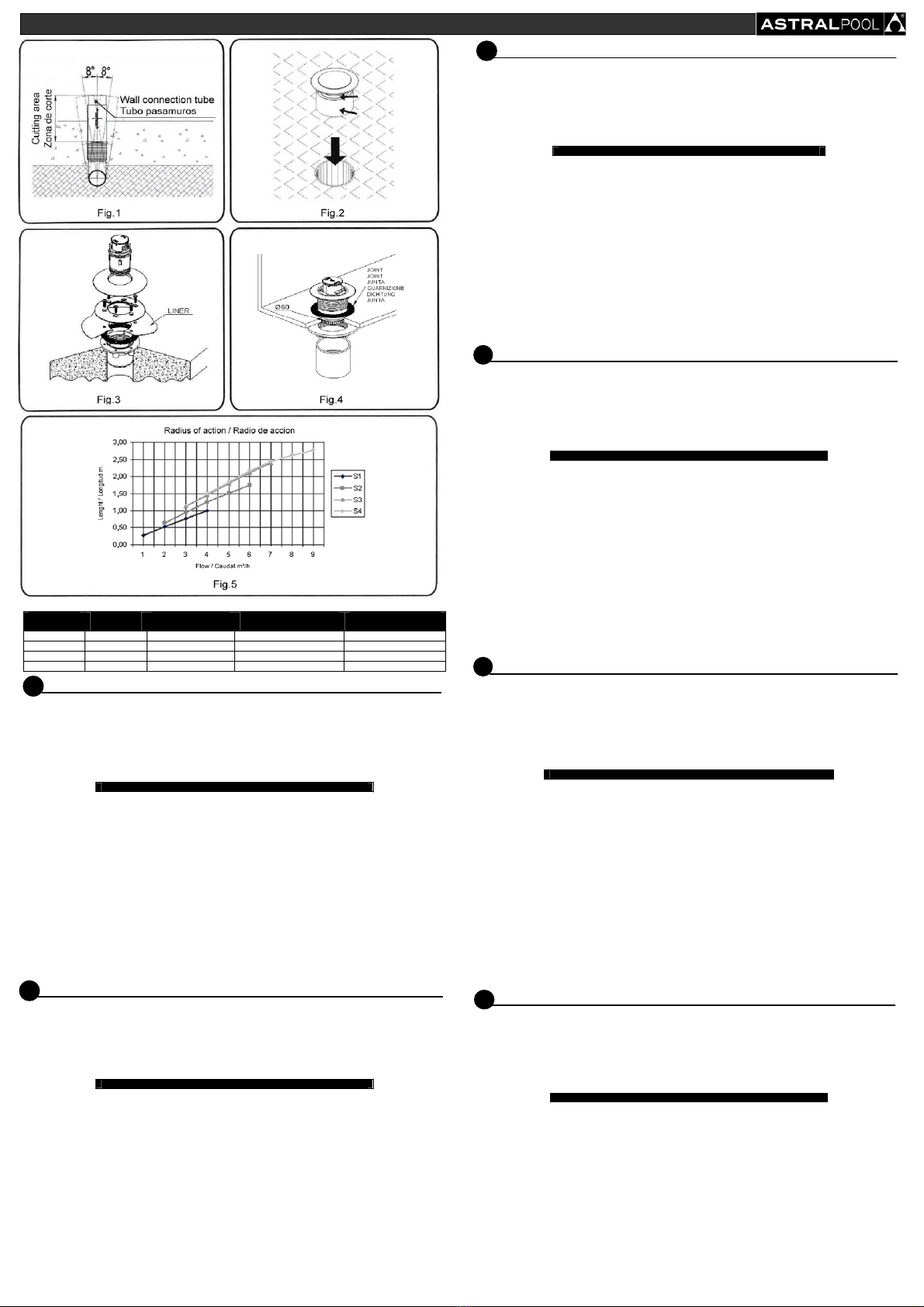
Table 1 / Tabla 1
Output /
Salida
Combination /
Combinación
Flow x nozzle m³/h /
Caudal x boquilla m³/h
Cleaning lenght in m. /
Longitud de limpieza en m.
Output surface mm² /
Superficie de salida mm²
S1 B+D 2 0,50 50
S2 A+D 3 1 100
S3 B+C 4 1,50 150
S4 A+C 5 1,80 200
EN NET ‘N’ CLEAN NOZZLE
Nozzle 26985
It can be installed in a bushing pipe (no. 26) or in a Ø75 PN6 pipe. In both cases, it should be aligned perpendicular to the bottom allowing
an 8º error with the pin bearing of the nozzle, leaving the pipe to project so that it can be cut once the bottom has been done. The bushing
pipe (no. 26) indicates the area where it should be cut (Fig. 1).
Place the protection cover (no. 23) on the corresponding side if the bushing pipe (no. 26) has been installed.
After placing the concrete and the gresite lining, cut the projecting pipe at the level of the bottom.
Place plenty of PVC glue on the inner part of the pin bearing and on the outside of the body housing bracket (no. 13)(Fig. 2) so that the two
PVC parts are well sealed to prevent water from passing inside the pin bearing. Place in the pipe until it is correctly aligned. Place the
protection cover (no. 23) in the body housing (no. 13).
VERY IMPORTANT. GLUE THE INSIDE PART OF THE PIN BEARING!
Nozzle 26986
It must be installed in a PVC Ø63 PN-6 pipe perpendicular to the bottom of the pool and projecting above the finished bottom.
After placing the concrete and gresite lining, cut the projecting pipe at the level of the bottom.
Place glue on the body housing (no. 14) and insert it in the pipe. Press the protection cover (no. 23) into place.
Nozzles 28499 – 28500 – 34540 (Fig.3)
Once the piping has been installed, it is recommended to glue the connection included in the nozzle (no. 25) so that it can be glued on the
outside of a Ø63 (EUR) or 2” (USA) pipe. If the connection is not used, the nozzle should be glued inside a Ø63 PN-10 pipe. In both cases,
the nozzle should be levelled to the bottom of the pool. Stick the adhesive protection in the nozzle.
After placing the concrete, remove the adhesive protection, stick the adhesive joint and then install the liner.
Place the flange (no. 11) using the corresponding screws (no. 10).
Cut the liner remaining inside the flange and press the trim in place (no. 9).
Nozzles 34540 are supplied with a connection bushing for 2” American standard piping.
Nozzle 21209 – 34330 (Fig. 4)
Mark the exact place where the nozzles are to be installed and make a Ø60mm hole on the bottom of the swimming pool.
Place the joint (no. 20) and the nozzle body (no. 15) from inside the pool and thread the nut of the unit (no. 21) from outside the pool.
Check that the joint is not creased.
Stick the connection (no. 25) using PVC glue and complete the installation with a Ø63 pipe.
Nozzles 34330 are supplied with a connection bushing for 2” American standard piping.
The cap (no. 22) can be used to perform the sealing test.
ATTENTION: The Bushing Pipe (code 21248-23665) is not supplied with this product.
Do no install nozzles if the bottom of the pool has a slope over 45º.
FBUSE NET ‘N’ CLEAN
Buse 26985
Vous pouvez l’installer sur un tuyau traversée de murs (nº 26) ou sur un tuyau de Ø 75 PN6. Dans les deux cas, il faut l’aligner
perpendiculairement au fond en permettant un écart de 8º avec le système de rotule de la buse et en laissant dépasser le tuyau pour pouvoir
le couper une fois le fond terminé. Sur le tuyau traversée de murs (nº 26) est signalé l’endroit où il faut couper (Fig. 1).
Placez le couvercle de protection (nº 23) sur le côté correspondant si vous avez installé le tuyau traversée de murs (nº 26).
Après le bétonnage et la pose du revêtement de grésite, coupez le bout de tuyau qui dépasse au ras du fond.
Mettez une grande quantité de colle pour PVC sur la partie interne de la rotule et sur la partie externe du support du corps logement (nº 13)
(Fig. 2) pour que les deux pièces de PVC soient bien fixées et pour empêcher que l’eau pénètre à l’intérieur de la rotule, puis introduisez-le
dans le tuyau jusqu’à obtenir l’alignement correct. Poser le couvercle de protection (nº 23) à pression sur le corps logement (nº 13).
TRÈS IMPORTANT : ENDUIRE DE COLLE LA PARTIE INTERNE DE LA ROTULE !
Buse 26986
Elle doit être installée sur un tuyau de PVC Ø 63 PN-6 perpendiculairement au fond de la piscine, devant dépasser au-dessus du fond fini.
Après le bétonnage et la pose du revêtement de grésite, coupez le bout de tuyau qui dépasse au ras du fond.
Introduisez le corps logement (nº 14) enduit de colle à l’intérieur du tuyau. Posez le couvercle de protection (nº 23) à pression.
Buses 28499 – 28500 – 34540 (Fig. 3)
Après avoir achevé l’installation des tuyaux, il est recommandé d’enduire de colle le raccord qui vous est fourni avec la buse (nº 25) pour
pouvoir le coller sur la partie externe d’un tuyau de Ø 63 (EUR) ou 2” (USA). Au cas où vous n’utiliseriez pas le raccord, il faudrait coller la
buse sur la partie interne d’un tuyau de Ø 63 PN-10. Dans les deux cas, la buse doit être mise au même niveau que le fond de la piscine.
Collez la protection adhésive sur la buse.
Après le bétonnage, enlevez la protection adhésive, collez le joint adhésif, puis installez le Liner.
Posez la bride (nº 11) à l’aide des vis respectives (nº 10).
Découpez ensuite le liner qui reste à l’intérieur de la bride, puis posez l’enjoliveur (nº 9) à pression.
Les buses 34540 sont livrées avec un manchon de raccordement pour tuyauterie 2” norme américaine.
Buse 21209 – 34330 (Fig. 4)
Marquez l’endroit exact où vous allez installer les buses, puis percez un trou de Ø 60 mm au fond de la piscine.
Placez ensuite le joint (nº 20) et le corps de la buse (nº 15) sur la partie interne de la piscine et vissez sur la partie externe l’écrou de
l’ensemble (nº 21). Vérifiez que le joint n’est pas plié.
Collez le raccord (nº 25) avec de la colle pour PVC et complétez l’installation avec un tuyau de Ø 63.
Les buses 34330 sont fournies avec un manchon de raccordement pour tuyauterie 2” norme américaine.
Vous pouvez utiliser la bonde nº 22 pour réaliser l’essai d’étanchéité.
ATTENTION : Le tuyau traversée de murs (code 21248-23665) n’est pas fourni avec cet article.
N’installez pas les buses si le fond a une dénivellation de plus de 45º.
ES BOQUILLA NET ‘N’ CLEAN
Boquilla 26985
Puede instalarse en un tubo pasamuros (nº 26) o en un tubo de Ø75 PN 6 . En ambos casos debe alinearse perpendicular al fondo
permitiendo un error de 8º con el sistema de rótula de la boquilla y dejando sobresalir el tubo para poder cortarlo una vez finalizado el fondo.
En el tubo pasamuros (nº 26) está indicado la zona dónde se debe cortar (Fig. 1)
Colocar la tapa protección (nº 23) por el lado correspondiente en caso que hayamos instalado el tubo pasamuros (nº 26).
Después del hormigonado y la colocación del revestimiento de gresite recortar la tubería saliente a ras del fondo.
Poner abundante cola para PVC en la parte interior de la rótula y en la parte exterior del soporte cuerpo alojamiento (nº 13) (Fig. 2) para que
las dos piezas de PVC queden bien sujetas y evitar el paso del agua por el interior de la rótula, seguidamente introducirlo en el tubo hasta
obtener la alineación correcta. Colocar la tapa de protección (nº 23) a presión en el cuerpo alojamiento (nº 13).
¡MUY IMPORTANTE ENCOLAR LA PARTE INTERIOR DE LA RÓTULA!
Boquilla 26986
Debe instalarse en un tubo de PVC Ø63 PN-6 perpendicular con el fondo de la piscina y sobresaliendo por encima del fondo acabado.
Después del hormigonado y la colocación del revestimiento de gresite recortar la tubería saliente a ras del fondo.
Entrar el cuerpo alojamiento (nº 14) impregnado de cola en el interior del tubo. Poner a presión la tapa protección (nº 23)
Boquillas 28499 – 28500 – 34540 (Fig. 3)
Una vez realizada la instalación de las tuberías se recomienda encolar la conexión incluida en la boquilla (nº 25) para poder encolar por el
exterior de un tubo de Ø63 (EUR) o 2” (USA). En el caso de no utilizar la conexión hay que encolar la boquilla por el interior de un tubo de
Ø63 PN-10. En ambos casos la boquilla debe nivelarse en el fondo de la piscina. Pegar la protección adhesiva en la boquilla
Después del hormigonado quitar la protección adhesiva, pegar la junta adhesiva y seguidamente instalar el Liner.
Poner la brida (nº 11) con los respectivos tornillos (nº 10).
Seguidamente cortar el liner que queda en el interior de la brida y colocar a presión el embellecedor (nº 9).
Las boquillas 34540 se suministran con un manguito de enlace para tubería 2” norma americana.
Boquilla 21209 – 34330 (Fig. 4)
Marcar el lugar exacto de instalación de boquillas y realizar un agujero de Ø60mm en el fondo de la piscina.
Seguidamente colocar la junta (nº 20) y el cuerpo boquilla (nº 15) por la parte interior de la piscina y roscar por la parte exterior la tuerca del
conjunto (nº 21). Comprobar que la junta no haya quedado arrugada.
Encolar la conexión (nº 25) con cola de PVC y completar la instalación con tubo de Ø63.
Las boquillas 34330 se suministran con un manguito de enlace para tubería 2” norma americana.
El tapón nº 22 se puede utilizar para realizar la prueba de estanqueidad.
ATENCION: El Tubo Pasamuros (código 21248-23665) no se suministra con este producto.
No instalar las boquillas en un desnivel del fondo superior a 45º.
I UGELLO NET ‘N’ CLEAN
Ugello 26985
Si può installare in un tubo passamuri (nº 26) o in un tubo di Ø 75 PN6. In entrambi i casi deve essere allineato perpendicolarmente al
fondo, essendo consentito un errore di 8º con il sistema di rotula dell’erogatore e lasciando sporgere il tubo per poterlo tagliare una volta
concluso il fondo. Nel tubo passamuri (nº 26) è indicata la zona dove si deve effettuare il taglio (Fig. 1).
Collocare il coperchio di protezione (nº 23) sul lato corrispondente nel caso in cui sia stato installato il tubo passamuri (nº 26).
Dopo la gittata di cemento e la collocazione del rivestimento di gresite, procedere a ritagliare la tubatura uscente, a filo del fondo.
Collocare una abbondante quantità di colla per PVC nella parte interna della rotula e nella parte esterna del supporto corpo alloggiamento (nº
13) (Fig. 2) affinché i due pezzi di PVC rimangano ben uniti, onde evitare il passaggio d’acqua all’interno della rotula, quindi introdurlo nel
tubo fino ad ottenere un corretto allineamento. Collocare il coperchio di protezione (nº 23) a pressione nel corpo alloggiamento (nº 13).
IMPORTANTE! INCOLLARE LA PARTE INTERNA DELLA ROTULA!
Ugello 26986
Si deve installare in un tubo di PVC Ø 63 PN-6 perpendicolare al fondo della piscina e sporgendo al di sopra del fondo finito.
Dopo la gittata di cemento e la collocazione del rivestimento di gresite, procedere a ritagliare la tubatura uscente, a filo del fondo.
Inserire il corpo alloggiamento (nº 14) impregnato di colla all’interno del tubo. Inserire il coperchio di protezione a pressione (nº 23).
Ugello 28499 – 28500 – 34540 (Fig. 3)
Una volta realizzata l’installazione delle tubature, si consiglia d’incollare la connessione inclusa nell’ erogatore (nº 25) per poter incollare
dalla parte esterna di un tubo da Ø 63 (EUR) o 2” (USA). Nel caso in cui non si utilizzi la connessione, si renderà necessario incollare
l’erogatore dall’interno di un tubo da Ø 63 PN-10. In entrambi i casi, l’erogatore deve essere livellato nel fondo della piscina. Attaccare la
protezione adesiva nell’erogatore.
Dopo la gittata di cemento, togliere la protezione adesiva, incollare la giunta adesiva e in seguito installare il Liner.
Inserire la flangia (nº 11) con le rispettive viti (nº 10).
In seguito, tagliare il liner che rimanga all’interno della flangia e collocare a pressione l’elemento di abbellimento (nº 9).
Gli erogatori 34540 vengono forniti con un manicotto di allaccio per tubatura da 2” norma americana.
Ugello 21209 – 34330 (Fig. 4)
Segnare il luogo esatto dell’installazione degli erogatori ed effettuare un foro da Ø 60 mm nel fondo della piscina.
In seguito, collocare la giunta (nº 20) e il corpo erogatore (nº 15) dalla parte interna della piscina e avvitare dalla parte esterna ildado
dell’insieme (nº 21). Controllare che la giunta non sia rimasta arrugata.
Incollare la connessione (nº 25) con colla per PVC e completare l’installazione con un tubo da Ø 63.
Gli erogatori 34330 vengono forniti con un manicotto di allaccio per tubatura da 2” norma americana.
Il tappo nº 22 si può utilizzare per realizzare la prova di tenuta stagna.
ATTENZIONE: il tubo passamuri (codice 21248-23665) non viene fornito con questo prodotto.
Non installare gli erogatori in un dislivello del fondo superiore a 45º.
D DÜSE NET ‘N’ CLEAN
Düse 26985:
Sie können eine Mauerdurchführung (Nr. 26) oder ein Rohr mit Ø75 PN 6 montieren. In beiden Fällen muss das Rohr senkrecht zum Boden
verlegt werden, wobei eine Abweichung von 8º zum Gelenksystem der Düse zulässig ist. Lassen Sie das Rohr herausstehen, damit Sie es
abschneiden können, sobald der Boden fertig ist. An der Mauerdurchführung (Nr. 26) ist der Bereich, in dem geschnitten werden soll,
angegeben. (Abb. 1)
Bringen Sie den Schutzdeckel (Nr. 23) auf der entsprechenden Seite an, falls Sie die Mauerdurchführung (Nr. 26) montiert haben.
Nach dem Betonieren und Anbringen der entsprechenden Verkleidung mit Steingut schneiden Sie die Rohre, die aus dem Boden stehen, ab.
Genügend PVC-Kleber innen auf dem Kugelgelenk und außen auf der Halterung des Aufnahmekörpers (Nr. 13) anbringen (Abb. 2), damit die
beiden Teile aus PVC gut befestigt werden und kein Wasser in das Innere des Gelenks gelangen kann. Führen Sie dann das Rohr ein, bis es
korrekt ausgerichtet ist. Den Schutzdeckel (Nr. 23) mit Druck auf dem Aufnahmekörper (Nr. 13) anbringen.
SEHR WICHTIG! DIE INNENSEITE DES KUGELGELENKS VERLEIMEN
Düse 26986:
Sie sollte in einem PVC-Rohr Ø63 PN-6 senkrecht zum Boden des Swimmingpools montiert werden, so dass sie aus dem fertigen Boden
herausragt.
Nach dem Betonieren und Anbringen der entsprechenden Verkleidung mit Steingut schneiden Sie die Rohre, die aus dem Boden stehen, ab.
Den Aufnahmekörper (Nr. 14) mit Leim getränkt in das Innere des Rohrs einführen. Den Schutzdeckel (Nr. 23) mit Druck anbringen.
Düsen 28499 – 28500 – 34540 (Abb.3)
Sobald die Rohrleitungen verlegt sind, sollte der Anschluss in der Düse verleimt werden, damit man außen an einem Rohr mit Ø63 (EUR)
oder 2” (USA) verleimen kann. Falls der Anschluss nicht benutzt wird, muss man die Düse innen in einem Rohr mit Ø63 PN-10 verleimen. In
beiden Fällen muss die Düse auf dem Boden des Schwimmbeckens nivelliert werden. Den Schutzaufkleber auf der Düse anbringen.
Nach dem Betonieren den Schutzaufkleber abziehen, die Klebedichtung anleimen und dann den Liner montieren.
Den Flansch (Nr. 11) mit den dazugehörigen Schrauben (Nr. 10) anbringen.
Anschließend den Liner, der noch im Flansch bleibt, abschneiden und den Zierdeckel (Nr. 9) mit Druck anbringen.
Die Düsen 34540 werden mit einem Verbindungsschlauch für die Rohrleitungen 2” amerikanischer Normung geliefert.
Düse 21209 – 34330 (Abb. 4)
Den genauen Ort der Anbringung der Düsen markieren und ein Loch mit einem Durchmesser von 60 mm auf dem Boden des
Schwimmbeckens bohren.
Bringen Sie dann die Dichtung (Nr. 20) und den Körper der Düse (Nr. 15) von innen im Becken an und schrauben Sie am äußeren Teil die
Schraubenmutter des Sets (Nr. 21) auf. Überprüfen Sie, dass die Dichtung keine Falten hat.
Den Anschluss (Nr. 25) mit PVC-Kleber verleimen und die Installation mit einem Rohr mit Ø63 vervollständigen.
Die Düsen 34330 werden mit einem Verbindungsschlauch für die Rohrleitungen 2” amerikanischer Normung geliefert.
Der Deckel Nr. 22 kann benutzt werden, um die Dichtigkeit zu überprüfen.
ACHTUNG: Die Mauerdurchführung (Artikelnr. 21248-23665) wurde mit diesem Produkt nicht mitgeliefert.
Die Düsen nicht mit einem Gefälle von über 45º auf dem Boden installieren.
P BOQUILHA NET ‘N’ CLEAN
Boca 26985
Pode ser instalada num tubo passa-muros (nº 26) ou num tubo de Ø75 PN6. Em ambos os casos deve ser alinhada perpendicularmente ao
fundo, permitindo um erro de 8º com o sistema de rótula da boca e deixando sobressair o tubo para poder cortá-lo depois de concluir o fundo.
No tubo passa-muros (nº 26) está indicada a zona por onde se deve cortar (Fig. 1)
Coloque a tampa de protecção (nº 23) pelo lado correspondente, no caso de ter instalado o tubo passa-muros (nº 26).
Depois de betonar e colocar o revestimento de gresite, recorte a tubagem saliente rente ao fundo.
Aplique uma quantidade generosa de cola para PVC na parte interior da rótula e na parte exterior do suporte corpo alojamento (nº 13) (Fig. 2)
para que as duas peças de PVC fiquem bem coladas e também para evitar a passagem da água pelo interior da rótula. Seguidamente,
introduza o conjunto no tubo até obter o alinhamento correcto. Coloque a tampa de protecção (nº 23) sob pressão no corpo alojamento (nº13)
É MUITO IMPORTANTE APLICAR COLA NA PARTE INTERIOR DA RÓTULA!
Boca 26986
Deve ser instalada num tubo de PVC Ø63 PN-6 perpendicular ao fundo da piscina, sobressaindo por cima do fundo acabado.
Depois de betonar e colocar o revestimento de gresite, recorte a tubagem saliente rente ao fundo.
Introduza o corpo alojamento (nº 14) impregnado de cola no interior do tubo. Coloque a tampa de proteção (nº 23) sob pressão.
Bocas 28499 – 28500 – 34540 (Fig. 3)
Uma vez realizada a instalação das tubagens, é recomendável aplicar cola na ligação incluída na boca (nº 25) para poder colar pelo exterior
de um tubo de Ø63 (EUR) ou 2” (USA). No caso de não utilizar a ligação, deve-se colar a boca pelo interior de um tubo de Ø63 PN-10. Em
ambos os casos a boca deve ser nivelada no fundo da piscina. Coloque a proteção adesiva na boca.
Depois de betonar, retire a proteção adesiva, cole a junta adesiva e seguidamente instale o Liner.
Coloque o flange (nº 11) com os respectivos parafusos (nº 10).
Seguidamente, corte os restos do liner existentes no interior do flange e coloque o friso (nº 9) sob pressão.
As bocas 34540 são fornecidas com uma união para tubos de 2” norma americana.
Boca 21209 – 34330 (Fig. 4)
Marque o local exato de instalação da boca e faça um furo de Ø60 mm no fundo da piscina.
Seguidamente, coloque a junta (nº 20) e o corpo boca (nº 15) pela parte interior da piscina e enrosque a porca do conjunto (nº 21) pela parte
exterior. Assegure-se de a junta não tenha ficado enrugada.
Cole a ligação (nº 25) com cola de PVC e complete a instalação com um tubo de Ø63.
As bocas 34330 são fornecidas com uma união para tubos de 2” norma americana.
A tampa nº 22 pode ser utilizada para realizar o teste de selagem.
ATENÇÃO: O tubo passa-muros (código 21248-23665) não é fornecido com este produto.
Não instale as bocas num desnível do fundo superior a 45º.


