manuals.online logo
Brands
  1. Home
  2. •
  3. Brands
  4. •
  5. Astro Tool
  6. •
  7. Crimping Tools
  8. •
  9. Astro Tool 612648 User manual

Astro Tool 612648 User manual

1 2-11-93 TI648-93-0
ASTRO TOOL CORP.
CONNECTOR ASSEMBLY TOOLING
CYCLE CONTROLLED C-FRAME STYLE CRIMP TOOL
612648 (M22910/7-1) AND ASSOCIATED TYPES
INSTRUCTIONS FOR USE OF 612648 HEX POP-IN DIE CRIMP TOOL
GENERAL:
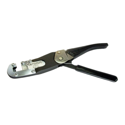
The Astro Tool Corp. Hex Pop-in Die Crimping Tool
is a cycle controlled, manually operated, C-frame tool for
crimping shield terminating ferrules, RF connector
fittings, and other terminations requiring an open frame
crimp tool.
There is only one set up operation required - installing
the required die set. Die sets are available in single,
double and triple hex cavities. Special form crimps are
also obtainable, consult the factory for details.
The Tool's precision cycle control mechanism assures
a high quality, repeatable crimp. The in-line action of the
dies and toggle mechanism reduces the compression force
required to complete the crimp.
For long life and optimum performance, this tool
should be kept clean and handled with the care of any
other precision device.
OPERATION
a. Open and close the tool several times and observe
the precision cycle-control mechanism. Note that the tool
cannot be opened without completing its cycle.
b. Identify the parts in figure #1:
1. Ratchet Handle
2. Movable Die Nest
3. Housing Cleat
4. Stationary Die Retaining Detent
Stationary
Die Retaining
Detent
Cleat
Housing Movable
Die Nest
Ratchet
Handle
Figure #1
c. Die Installation
2 2-11-93 TI648-93-0
1. The tool must be in the fully open position as
shown in figure #2.
Movable Die
Figure # 2
2. Locate the Movable Pop-in Die and insert the
die post into the die nest. Note the off-center die
post. The Movable Pop-in Die can only be inserted
in one direction. See figure # 2
NOTE: The Movable Pop-in Die must be installed
first.
3. Locate the Stationary Pop-in Die and engage the
flat end of the Die with the housing cleat. Rotate the
die in a clock-wise direction to engage it with the
Stationary Die Retaining Detent, see figure #3.
Observe that the Stationary Pop-in Die is installed
parallel to the side plates and that it is not skewed in
any way.
Stationary Die
Retaining Detent
Figure #3
CAUTION:
VERIFY THAT THE STATIONARY DIE IS
INSTALLED CORRECTLY. IMPROPER
INSTALLATION WILL RESULT IN DAMAGE
TO THE TOOL OR THE DIE SET.
4. Cycle the tool to set the die.
d. Crimping Operation
1. The tool must be in the fully open position.
Insert the prepared connector through the tool
opening and place in the appropriate cavity. For RF
connector fittings use the die face as a locational
stop. For shield terminations locate the crimp by eye.
2. Squeeze the handles together until the positive
stop is reached. The tool will release and return to
the fully open position.
3. Remove the crimped termination.
e. Die Removal
1. The tool must be in the fully open position.
2. To remove the Stationary Pop-in Die, locate the
DRT7. Insert the DRT7 into the hole in the top of
the tool, as shown in figure #4, and tap lightly on
the end indicated. The Stationary Pop-in Die will
drop from the tool.
NOTE: Always remove the Stationary Pop-in Die
First.
DRT7 DRT7
Figure #4
3. To remove the Movable Pop-in Die, position the
DRT7 as shown in figure #4, and tap upward lightly
to release the die.
f. Tool Calibration
1. The hand pressure required to cycle the tool
with a set of dies in it should be set at 20-50 lb.
Astro has the AT903 spring tester available for this
purpose.
Adjustment Screw
3 2-11-93 TI648-93-0
Figure #5
2. If calibration of the hand pressure is required,
locate the adjustment screw in the Movable Die Nest
by closing the tool. Using a flat blade screwdriver,
rotate the screw to the right to decrease the pressure,
to the left to increase the hand pressure. See figure #
5
3. When hand pressure calibration is achieved,
lock screw in place using an appropriate NON-
PERMANENT sealant.
g. Tool Gaging
1. Astro Tool Corp. manufactures flat GO-NO GO
pin assemblies for many of the dies used by the
612648 crimp tool. Contact the factory for your
specific requirements.
GO Pin Inserted
Into Cavity
Figure #6
2. With a die set properly installed, cycle the tool
into the fully closed position. Insert the appropriate
GO sized flat pin into the hex cavity. It shall freely
enter the hex cavity. See figure # 6. Remove the GO
pin and attempt insert the NO-GO pin into the hex
cavity. It should not enter the cavity.
DO NOT CRIMP GAGE, TOOL DAMAGE
WILL RESULT.
ASTRO TOOL CORP. MANUFACTURERS OF INSTALLING, REMOVAL AND CRIMP TOOLS
21615 S.W. T-V HWY.•BEAVERTON OREGON 97003 •503-642-9853 •FAX 503-591-7766
CONNECTOR ASSEMBLY TOOLING

This manual suits for next models

1

Other Astro Tool Crimping Tools manuals

Astro Tool 612596 User manual

Astro Tool

Astro Tool 612596 User manual

Astro Tool 620667 User manual

Astro Tool

Astro Tool 620667 User manual

Astro Tool AMT4001 User manual

Astro Tool

Astro Tool AMT4001 User manual

Astro Tool 620667 Operating instructions

Astro Tool

Astro Tool 620667 Operating instructions

Astro Tool 615717 User manual

Astro Tool

Astro Tool 615717 User manual

Astro Tool 615708 User manual

Astro Tool

Astro Tool 615708 User manual

Astro Tool TGV101 User manual

Astro Tool

Astro Tool TGV101 User manual

Astro Tool 613214 User manual

Astro Tool

Astro Tool 613214 User manual

Astro Tool MS 3191-4 User manual

Astro Tool

Astro Tool MS 3191-4 User manual

Astro Tool 616336 User manual

Astro Tool

Astro Tool 616336 User manual

Popular Crimping Tools manuals by other brands

Emerson Klauke MAPAX325CFM manual

Emerson

Emerson Klauke MAPAX325CFM manual

BGB 295060 Operation guide

BGB

BGB 295060 Operation guide

TE Connectivity ERGOCRIMP 4-1579001-1 instruction sheet

TE Connectivity

TE Connectivity ERGOCRIMP 4-1579001-1 instruction sheet

Parker Parkrimp 2 - 83CE-083U instruction manual

Parker

Parker Parkrimp 2 - 83CE-083U instruction manual

Legend MSS-KREC-54AC SAFE OPERATION & MAINTENANCE INSTRUCTIONS

Legend

Legend MSS-KREC-54AC SAFE OPERATION & MAINTENANCE INSTRUCTIONS

molex 63811-8100 Specification sheet

molex

molex 63811-8100 Specification sheet

Greenlee GATOR EK1550LX Operation manual

Greenlee

Greenlee GATOR EK1550LX Operation manual

TE Connectivity SDE-SA instruction sheet

TE Connectivity

TE Connectivity SDE-SA instruction sheet

TE Connectivity SDE-SA instruction sheet

TE Connectivity

TE Connectivity SDE-SA instruction sheet

Textron Klauke K 16 instruction manual

Textron

Textron Klauke K 16 instruction manual

Textron Klauke K 63 instruction manual

Textron

Textron Klauke K 63 instruction manual

molex 207129 Series Specification sheet

molex

molex 207129 Series Specification sheet

Textron Greenlee GATOR EK1230L230 Operation manual

Textron

Textron Greenlee GATOR EK1230L230 Operation manual

Emerson Klauke EK 120IDCFM Assembly instructions

Emerson

Emerson Klauke EK 120IDCFM Assembly instructions

Textron Greenlee GATOR EK12IDLT Operation manual

Textron

Textron Greenlee GATOR EK12IDLT Operation manual

Cembre B540ND-BVA Operation and maintenance manual

Cembre

Cembre B540ND-BVA Operation and maintenance manual

TE Connectivity 2063525-1 instruction sheet

TE Connectivity

TE Connectivity 2063525-1 instruction sheet

TE Connectivity SDE-SA instruction sheet

TE Connectivity

TE Connectivity SDE-SA instruction sheet

manuals.online logo
manuals.online logoBrands
  • About & Mission
  • Contact us
  • Privacy Policy
  • Terms and Conditions

Copyright 2025 Manuals.Online. All Rights Reserved.