ASTRO AMC-2000 User manual

ASTRO
ENVELOPE FEEDER
AMC-2000
INSTALLATION AND OPERATING INSTRUCTIONS

INTRODUCTION
Thank you for purchasing the Astro Envelope Feeder. It is fast, efficient, reliable, and designed to provide many
years of trouble-free service.
Numerous built-in features of the Envelope Feeder combined with state-of-the art technology make this unit
superior. Top load/bottom vacuum feed provides continuous printing of various sized envelopes, cards, and tags.
Uniquely designed conveyor board with its synchronized side guides and push guide provides accurate registration
for secondary color operations. Photoelectric sensor is the key element in the synchronization of the Envelope
Feeder to the Duplicator and is designed to give many years of virtually trouble-free operation.
Flexibility. Optional Auxiliary Installation Kit provides compatibility to additional presses or duplicators of the
same type. An optional Dual Stream Feed Kit is available for feeding different size envelopes simultaneously, to
double your production needs.
SPECIFICATIONS*
VOLTAGE REQUIREMENTS:
115 VAC, 60 Hz, 10 A
OPTIONAL AVAILABILITY:
220 VAC, 50 Hz, 5 A
ENVELOPE DIMENSIONS:
Minimum: 3" x 5" (7.6 x 12.7 cm)
Maximum: 11" x 16-1/4" (27.9 x 41.3 cm)
MAXIMUM FEEDING SPEED:
Governed by Press
MACHINE DIMENSIONS:
Width: 20" (50.8 cm)
Length
: 37" (94 cm)
Height
: 42" (106.7 cm)
Weight:
150 lbs. (68 kg)
AVAILABLE OPTIONS:
Conveyor Delivery (CD-100)
Pulse
Generator Kits (A-202)
Dual Stream Feed Kit (A-203)
* Manufacturer reserves the right to change specifications without written notice.
SAFETY PRECAUTIONS
THIS EQUIPMENT PRESENTS NO PROBLEM WHEN USED PROPERLY.
OBSERVE SAFETY RULES WHEN OPERATING FEEDER.
READ THIS MANUAL CAREFULLY AND FOLLOW RECOMMENDED PROCEDURES.
1. KEEP HANDS, HAIR, AND CLOTHING CLEAR OF ROLLERS, TAPES AND
OTHER MOVING PARTS.
2. ALWAYS TURN MACHINE OFF BEFORE MAKING ADJUSTMENTS OR
CLEANING MACHINE.
3. DISCONNECT POWER CORD WHEN MAKING ANY MACHINE ADJUSTMENTS OR
PERFORMING ANY MAINTENANCE NOT COVERED IN THIS MANUAL.
CAUTION
THIS EQUIPMENT MUST BE CONNECTED TO A PROPERLY GROUNDED OUTLET.
FAILURE TO DO SO CREATES A POTENTIAL DANGER OF ELECTRICAL SHOCK.

Page 1
PARTS LIST
The following parts are included with this machine.
Check and identify all parts with those listed below:
A.
ENVELOPE FEEDER
84-000-00
B.
STAND WITH PUMP ASSEMBLY
(See Page 13 & 14)
C.
PULSE GENERATOR
ASSEMBLY
84-140
-00
D.
PLASTIC TIES (4)
123-0113
E.
FRONT ENVELOPE GUIDE R/H
71-140-08
F.
FRONT ENVELOPE GUIDE L/H
71-140-10
G.
CENTER ENVELOPE GUIDE
71-140-13
H.
REAR ENVELOPE GUIDE
84-108-20
I.
PAPER BOARD STOP
84-100-82
J.
BRACKET, PRESS SIDE GUIDE
84-101-51
K.
HEX NUT
84-101-49
L.
WASHER, 1/4 PLAIN
123-0063
M.
SHEET SEPARATOR (4)
71-109-05
N.
SPRING
84-120-10
O.
SUCTION CUP (4)
71-134-15
P
ALLEN WRENCH – 1/16"
123-0057
Q.
ALLEN WRENCH – 3/32"
123-0058
R.
FUSE, 2 AMP (FAST BLO)
123-0285
S.
FUSE, 10 AMP (SLO BLO)
123-0090
T.
SUCTION FOOT CAP (2)
123-0415
U.
WHEEL CASTERS (4)
(2) 123-0517, (2) 123-0521
V.
NEEDLE VALVE
84-106-04
W.
SPRING
84-120-31

Page 2
UNPACKING INSTRUCTIONS
1. Unpack Stand and Feeder. Check parts against Parts List on Page 1.
2. Install four casters to base of Stand.
3. Place Feeder on top of Stand by locating two mating points on bottom of Feeder. [Fig. 1]
4. Match two mating points with corresponding holes on top of Stand and slide into slots.
5. Locate two thumbscrew holes at front of Stand.
6. Install two (2) 1/4-20 x 1/2 inch thumbscrews provided in Accessory Kit.
7. Secure Feeder by tightening thumbscrews into threaded holes.
Figure 1

Page 3
INSTALLATION INSTRUCTIONS
1. Unplug Duplicator.
2. Remove rear right upper Side
Cover from Duplicator.
3. Remove cross-brace bolt near
buckle control gear.
4. Place Pulse Generator
[Fig. 2] lower bracket over
cross-brace bolt hole and
reinstall bolt. DO NOT
TIGHTEN at this time.
5. Swing Pulse Generator all the
way to the left until gears engage
and secure bolt.
6. Route Pulse Generator cable
through large hole at rear of
Duplicator Side Frame. Use
plastic ties (P/N 123-0113) to prevent cable from entering moving parts of Duplicator.
WARNING: FAILURE TO DO THIS RESULTS IN SERIOUS DAMAGE TO
ENVELOPE FEEDER AND DUPLICATOR.
7. Check gap between Sensor and Magnet Assembly by rotating Duplicator by hand. (Should
be 1/32" ± 0.010"). Adjust gap by loosening sensor mounting screws and moving bracket.
8. Lift up Flip-up Paper Guide to accommodate Feeder.
NOTE: If Duplicator is equipped with T-51 Head (P/N 84-101-51),
mount Guide Support Bracket on Duplicator.
a) Remove rear hex nut securing Bail Bar Bracket to Side Frame.
b) Place Guide Support (P/N 84-101-51) over bolt and secure in place with
nut (P/N 84-101-49).
c) Lift Flip Guide up, swing Guide Support up and rest Flip Guide on it.
9. Reinstall Duplicator Side Cover.
10. Remove Bail Bar.
11. Position Paper Guides to widest position.
NOTE: On 8000 Series Duplicators, remove collar on inside of non-operator’s side of
Side Guide that limits movement of Side Guides. Reinstall on outside of shaft.
This permits movement of Side Guides to a position wide enough to accommodate
Envelope Feeder.
12. Push down Table Release Lever and move paperboard halfway down.
13. Lift paperboard Stop Lever [Figure 3] and place Paperboard Stop (P/N 84-100-82) on
stud. Release lever so it rests in groove of Paper Board Stop. This prevents paperboard
from coming up and hitting Feeder.
Figure 2

Page 4
Figure 3
WARNING: FAILURE TO DO THIS RESULTS IN SERIOUS DAMAGE TO
ENVELOPE FEEDER AND DUPLCATOR.
14. Move Paper Stack Height Adjustment to low position.
15. Turn Duplicator Hand Wheel so suction feet are in uppermost position. Remove two outer
suction feet from Duplicator.
WARNING: FAILURE TO DO SO MAY DAMAGE OUTER SUCTION FEED AND
PREVENT PROPER OPERATION OF DUPLICATOR.
Figure 4

Page 5
16. Roll Feeder up to Duplicator. Adjust height of Conveyor to match Duplicator Front
Apron. If Feeder Front Stop Plate Hook is not even with upper edge of Duplicator’s Front
Apron, adjust Feed Stand. To adjust Stand height [Figure 4]: Loosen two knobs on
either side of Stand. Turning locking knobs counterclockwise unlocks Stand, which allows
it to be adjusted. Adjust height by turning third knob (Adjusting Knob) clockwise to raise
height of Stand, and counterclockwise to lower it. Tighten locking knobs after height is
adjusted. If Feeder is to be used on more than one Duplicator, adjust Duplicators to one
height (eliminating additional set up time).
17. Position slots on Feeder Front Stop Plate against Duplicator’s Paper Height Regulators.
Lift Feeder Conveyor and hook it over Duplicator’s Front Apron.
NOTE: Allow proper clearance between Height Regulators and Feeder Stop Plate.
18. Move Duplicator Paper Guides in until they touch Feeder Conveyor. Tighten Feeder
Conveyor clamp screw (located under Conveyor).
19. Connect Pulse Generator cable to Feeder cable.
Plug Feeder into 115VAC, 15 AMP outlet.
WARNING: POWER FLUCTUATIONS CAUSED BY AN OVERLOAD
OF EQUIPMENT ON SAME BRANCH CIRCUIT MAY AFFECT
FEEDER PERFORMANCE.
20. Install (84-120-31) Spring on (84-106-04) Needle Valve. Screw Needle Valve Assembly
into side of Envelope Feeder. (Figure 5)
WARNING: DO NOT OVERTIGHTEN VALVE AS DAMAGE TO
VALVE BODY CAN OCCCUR.
Figure 5

Page 6
CONTROLS
CONTROL PANEL
1. PUMP – Turns Feeder Pump ON and OFF.
2. SET-UP – Feeder makes a full cycle bringing one envelope to Press. Mode Switch (#5)
must be on MANUAL; Pump Switch (#7) must be ON and drive motor running.
3. MODE SWITCH – In depressed position, activates Speed Control (#4). In released
position, activates Pulse Generator and synchronizes Feeder with Press.
4. FEEDER SPEED CONTROL – In MANUAL mode, enables operator to adjust speed
of drive motor during set-up.
5. POWER SWITCH – Turns Feeder ON and OFF.
6. FUSE – Drive Motor, 2 AMPS
7. FUSE – Pump, 10 AMPS
VACUUM BLEED VALVE
Vacuum Bleed Valve is located on left-side Feeder Frame.
Turning it clockwise increases amount of vacuum going into
suction feet. Turning it counterclockwise decreases vacuum.
Figure 5
Figure 7
Figure 6

Page 7
OPERATING INSTRUCTIONS
1. Adjust Envelope Feeder Stand to height of Press Front Feed Plate.
2. Hook Front Feed Plate on Envelope Feeder over bar on Press' Feeder. Tighten clamp
screw assembly securely.
3. Plug Pulse Generator into connector
provided on Envelope Feeder.
Plug Pump into receptacle on
Envelope Feeder.
4. Plug Envelope Feeder into
wall receptacle.
5. Attach Front Envelope Guides
[#1, Fig. 8] approximately in middle
of Feeder (as shown).
6. Place an envelope in Guides.
7. Attach Rear Envelope Guide
[#2, Fig. 8] using slot in Feeder floor
nearest rear end of envelope, then
adjust Anti-skewing Guides to sides
of envelope [#3, Fig. 8].
8. Adjust Envelope Guides so there is
no more than 1/16" (1.6 mm) clearance in all directions.
NOTE: EXCESSIVE CLEARANCE RESULTS IN MISFEEDING AND
IMPROPER PERFORMANCE.
9. Position suction cups distributed evenly with outside cups approximately 3/4" (2 cm) from
ends of envelope. NOTE THAT ENVELOPE SIZE DETERMINES HOW MANY
SUCTION CUPS SHOULD BE USED.
10. Place suction foot vacuum caps (P/N:
123-415) on suction feet not used.
11. Using scale on Feeder floor and scale
on Conveyor, [#1, Fig. 9], and scale on
Conveyor, [#2, Fig. 9], roughly adjust
Stop Guide, [#4, Fig. 9] and Push
Guide, [#3, Fig. 9] so envelope coming
down will clear them.
Figure 9
Figure 8

Page 8
12. Place a small stack of envelopes in Guides.
13. Using adjusting thumbscrew, make sure right edge of Push Guide is perpendicular to
Front Stop Plate for accurate squareness.
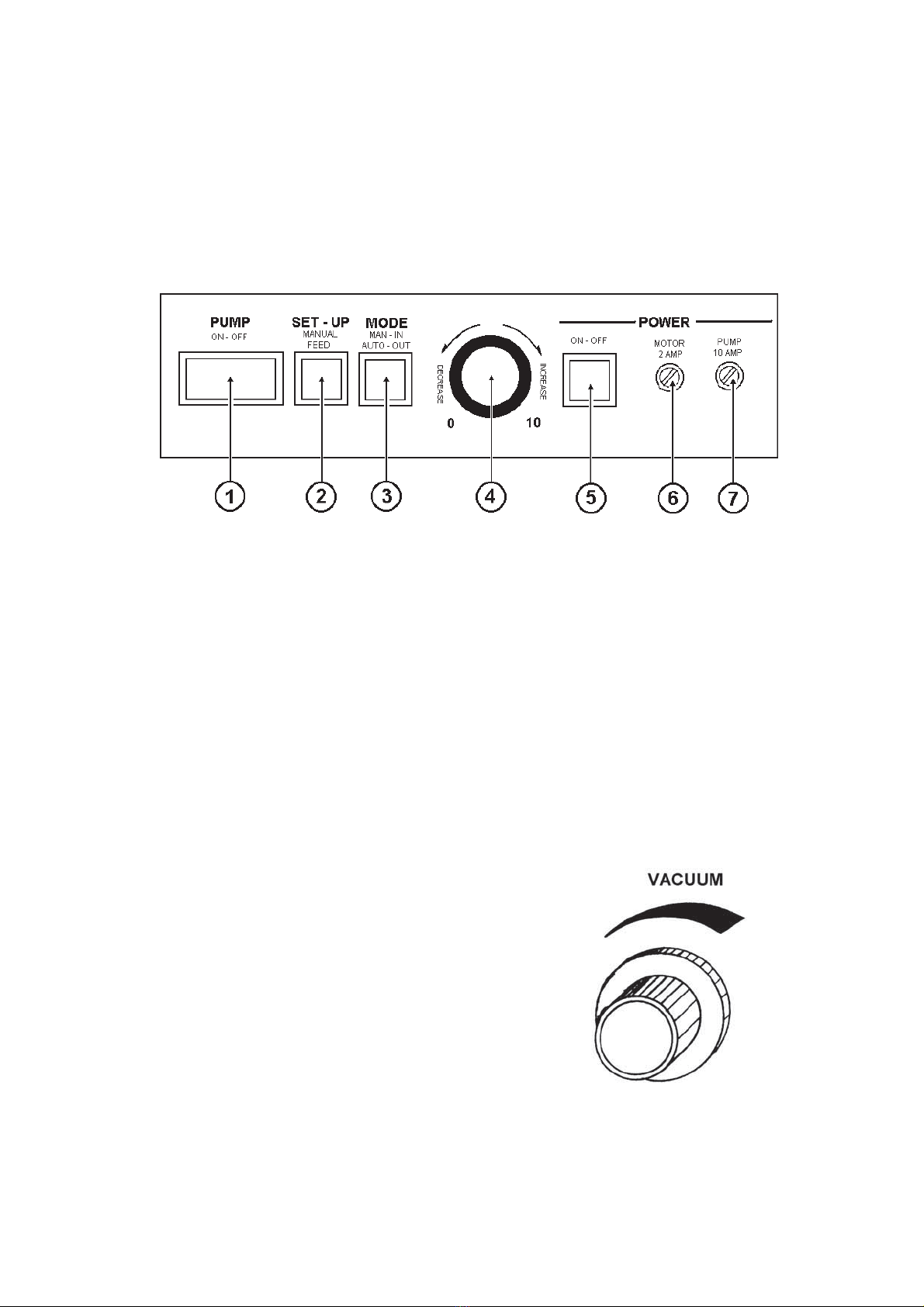
14. Turn Feeder ON, set Mode Switch to MANUAL. Turn Speed Control clockwise so
Conveyor Tapes are moving slowly.
15. Turn Vacuum Switch ON.
16. Press SET-UP Switch momentarily. This activates Suction Cup Bar and brings down an
envelope. When envelope moves down Conveyor to Duplicator, make sure it clears Push
Guide and does not touch springs on Stop Guide.
17. Turn VACUUM Switch OFF and press SET-UP Switch again. This activates jogging
mechanism. Adjust Jogger Guide so envelope just touches springs on Stop Guide.
NOTE: TOO MUCH JOG CAN AFFECT REGISTRATION.
18. Adjust Conveyor Tapes by moving Tape Guides (located under Conveyor portion of
Feeder) while tapes are running slowly.
EXAMPLE: For No. 10 envelopes, use three (3) tapes. One over Stop Guides
(approx. 3/8" (1 cm) from springs), one over Push Guide (approx. 1/4" (6 mm) from
right edge) and one tape under skid wheel. For wider envelopes, use additional tapes
as needed.
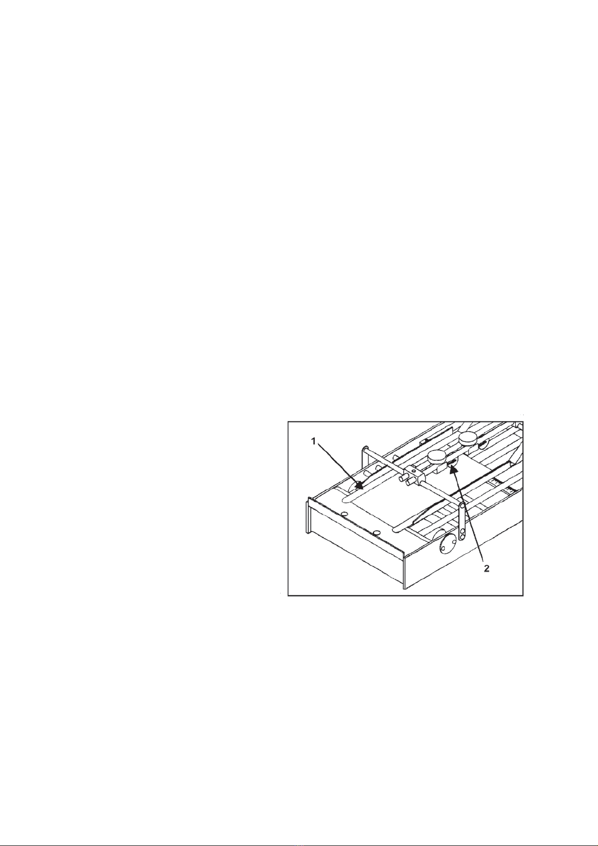
19. Adjust retainer straps [#1, Fig. 10]
over Stop and Push Guide Tapes.
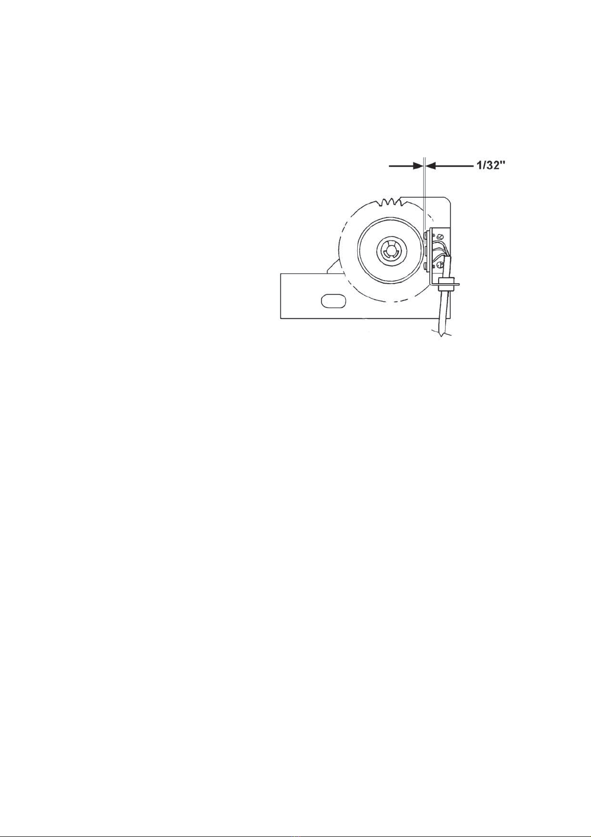
20. When envelope is against Front
Stop Plate, position front skid
wheel [#2, Fig. 9] so it lightly
touches trailing edge of envelope.
21. Turn Press Pump ON.
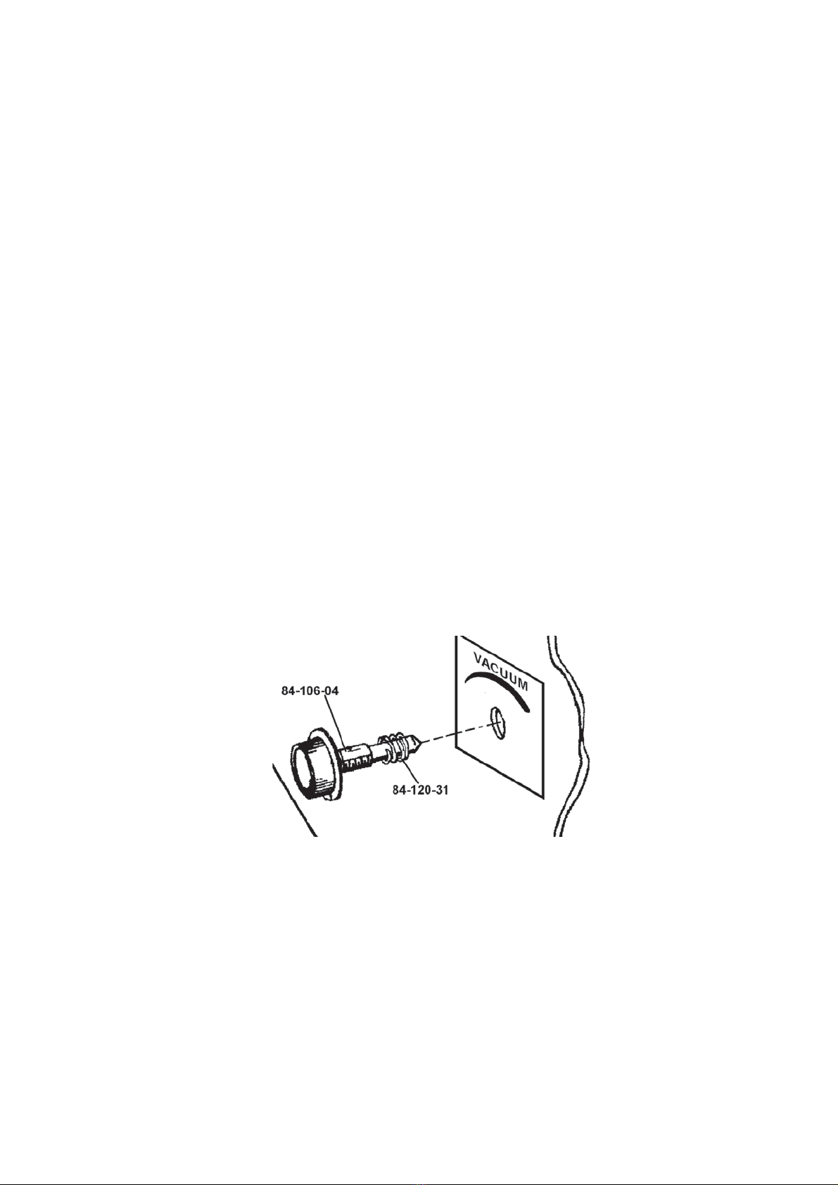
22. Turn Press Blowers OFF, turn
Press Vacuum Knob to Full.
23. Using Press Hand Wheel; pass
envelope through Press.
NOTE: Make sure envelope
goes into Grippers firmly.
Adjust Buckle Control on
Press if necessary.
24. Set Duplicator on lowest speed.
25. Set Feeder Mode Switch to AUTO position.
26. Turn Feeder Vacuum ON.
Figure 10

Page 9
27. Press SET-UP Switch momentarily. This brings down the envelope.
28. Turn Press Vacuum ON.
Feeder is equipped with a Photoelectric
Sensor [#1, Fig. 11], which synchronizes
Feeder with Press and prevents jam-ups. In
case Press does not pick up an envelope,
Feeder will not send another envelope. This
acts as a built in jam detector. Feeder remains
neutral as long as an envelope covers
Photoelectric Sensor. To start feeding again,
turn Feeder Vacuum and Drive Motor OFF.
Correct problem on Press and/or Feeder.
Follow Steps 26-28 to start feeding again.
NOTE: Make sure Feeder is set up so envelopes are fed over Photosensor. Also,
make sure no foreign objects, (e.g. lint, paper) cover Photosensor. It is essential to
Feeder's operation that Photosensor “sees” an envelope.
TO START AND STOP FEEDING: Use Duplicator Pump Switch. DO NOT use
Feeder Power Switch. Feeder Power Switch should be turned “ON” when job is
started, and remains on until job is complete.
Press speed can be changed while Feeder is feeding envelopes. Electronic circuitry of
Envelope Feeder is designed to respond automatically to operational commands of Press.
WARNING: Any speed changes to Press should be done GRADUALLY. Rapid
changes of speed affect registration and may cause misfeeding.
Figure 10
Figure 11

Page 10
OPERATING HINTS
A. Do not bend envelopes when setting Side Guides. Front
and Rear Guides must be snug against envelopes.
B. Form envelopes as required to maintain flatness to suction
cups to improve feeding consistency.
C. Be sure bottom envelope (in a stack of envelopes or tag
stock), rests on Sheet Separators.
D. Front Side Guides contain adjustable sheet separator clips.
Clips project 3/32" (2.4 mm) beyond face of Guides.
Adjustment is rarely required.
1. Misfeeding may occur if clips extend too far under
envelopes. First increase vacuum and test run; then, if
required, move clip [#1, Fig. 12] to front using set
screw behind them.
2. Double feeding may occur if clips are not under
envelopes far enough. First decrease vacuum and test run;
then, if required, move clips to front.
Vertical position of clips is also adjustable. Loosen two screws [#2, Fig. 12] and position
bottom of clip flush with bottom of Guide.
Figure 12

Page 11
LUBRICATION INSTRUCTIONS
WARNING!
MACHINE MUST BE UNPLUGGED FROM POWER
RECE
PTACLE WHILE PERFORMING LUBRICATION,
MAINTENANCE, OR CLEANING PROCEDURES.
CAUTION
TAKE CARE TO KEEP LUBRICANTS FROM
ELECTRICAL TERMINALS, SWITCHES, AS WELL AS
ROLLERS, BELTS AND RUBBER PARTS.
When lubricating, pay particular attention to oil holes and all sliding parts.
NOTE: Paper residue, dust, ink and other foreign materials MUST BE REMOVED from
gears, working levers, shafts, and mechanisms before new lubricants are applied. This
prevents undue wear caused by abrasion from these residues. Areas around or adjacent to
lubricated parts and surfaces MUST BE FREE of dust and foreign material.
LUBRICATION INTERVALS
Regular lubrication of oil ports (indicated by red) should be performed every 30 days on
machines that operate 30-40 hours per week.
LUBRICANTS
OIL: S.A.E. #20 non-detergent engine oil, or equivalent.
GREASE: Commercial lithium grease.
GENERAL LUBRICATION
1. Cams and Gears – Clean and lightly oil.
2. Springs and Levers – Grease lightly.
NOTE: Before greasing springs and spring levers, existing lubricant
MUST BE REMOVED. Apply new grease sparingly – only at hook ends of Spring,
not on body.
3. Chains and Sprockets – Lubricate using commercial lithium grease.
NOTE: In order to gain access to most lubricating points,
Front Cover Assembly MUST BE REMOVED.

Page 12
FRONT COVER ASSEMBLY REMOVAL
1. Turn power “ON”.
2. Set MODE Switch to MANUAL.
3. Turn Speed Control Knob CLOCKWISE so Conveyor tapes move slowly.
4. Press Set Up Switch momentarily.
5. Wait until Upper Pull-Out Roller touches Lower Pull-Out Roller and turn power OFF.
6. Unplug Feeder.
7. Unscrew 4 thumbscrews (2 on each side of Feeder) [#1, Fig. 13].
8. Remove Front Cover Assembly [#2, Fig. 13].
Figure 13

Page 13
STAND WITH PUMP

Page 14
STAND WITH PUMP
KEY
PART NO.
DESCRIPTION
QTY.
1.
156-102-18
ELEVATOR BRACKET
2
2.
123-0017
SCREW, 10-32 x 1/4 PH, TRUSS
32
3.
156-103-05
PANEL – BASE, PUMP COVER
1
4.
156-103-07
SIDE PLATE R/H
1
5.
156-103-06
SIDE PLATE L/H
1
6.
156-103-25
ELEVATOR BRACKET SUPPORT
2
7.
123-0695
SPRING PIN, 3/32 x 1/2
1
8.
156-103-27
COLLAR
1
9.
123-0841
CARRIAGE BOLT, 5/16 -18 x 1
4
10.
156-103-12
HELIX ANGLE WORM
2
11.
156-103-11
WORM GEAR 20 TEETH
1
12.
123-0018
ROLL PIN, 1/8 x 3/4 – BLACK
3
13.
156-103-08
SPROCKET 25B13
2
14.
156-103-09
IDLER PULLEY
2
15.
156-103-21
WORM SHAFT
1
16.
123-0135
KNOB
2
17.
156-103-20
DRIVE SHAFT
1
18.
156-103-26
CHAIN, TRANSMISSION ROLLER
2
19.
123-0200
CONNECTING LINK, CHAIN
4
20.
156-103-23
ELEVATOR BRACKET SUPPORT
2
21.
86-103-04
COVER, SIDE PANEL
2
22.
156-103-03
SIDE PANEL, L/H
2
23.
123-0293
KNOB, HEIGHT ADJUSTMENT
1
24.
86-103-06
PUMP COVER, STAND
2
25.
123-0707
RUBBER GROMMET, 1/2 ID x 3/4 OD
1
26.
156-103-04
SIDE PANEL, R/H
1
27.
123-0143
SCREW, HEX 1/4-20 x 5/8
4
28.
123-0063
WASHER, PLAIN 1/4 -MOTOR & PUMP
8
29.
123-0064
LOCK WASHER, 1/4
8
30.
123-0054
NUT, HEX 1/4-20
8
31.
123-0517
CASTER, NON-LOCKING
2
32.
123-0521
CASTER, LOCKING
2
33.
86-103-31
BASE WELDMENT
1
34.
84-103-07
VACUUM PUMP ASSEMBLY, 115V
1
35.
123-0131
CLAMP, HOSE
1
36.
84-106-41
HOSE, PUMP
1
37.
123-0051
NUT, HEX 5/16-18
4
38.
123-0757
SET SCREW, 6-23 x1/4 STD CUP PT
4
39.
123-0855
LOCKING WASHER, 5/16
4
* 40.
84-140-78
RELAY BOX 220V / 50 Hz
1
* 41.
123-0436
TRANSFORMER, 220V / 50 Hz
1
* 42.
84-103-10
VACUUM PUMP, 220V / 50 Hz
1
43.
56-108-22
THUMBSCREW
1
44.
123-0096
WASHER, PLASTIC 3/8 x 3/4 x 1/16
2
45.
123-0311
WASHER, PLASTIC 9/32 x 3/4 x 1/16
2
46.
123-0701
SCREW, 10-32 x 3/16 PH TRUSS HD
4
47.
123-0034
ROLL PIN, 1/8 x 5/8
1
*48.
123-0050
NUT, 10-32 x 5/16 HEX ZINC
6
*49.
123-0024
SCREW, 10-32 x 3/8 PH TRUSS HD MS ZINC
6
*50.
123-0237
STAR WASHER, #10 EXTERNAL
6
*51.
123-0262
WASHER, #10 3/16 x 3/8 x .032
6
52.
123-0312
WASHER, PLASTIC 5/16 x 1/2 x .030
2
53.
123-0145
FITTING
1
**
K247
SERVICE KIT, OLD STYLE PUMP
**
K478
SERVICE KIT, NEW STYLE PUMP
**
AK524
FELT, NEW STYLE PUMP ONLY
* ITEMS 40, 41, 42 ARE FOR 220V / 50 Hz ONLY.
** PARTS NOT SHOWN.

Page 15

Copyright © 2015 Astro Machine Corporation
Elk Grove Village, Illinois 60007
07/01
/2015
PART NUMBER: 200-AMC2000 Rev. A
Table of contents
Other ASTRO Industrial Equipment manuals
Popular Industrial Equipment manuals by other brands

Belmash
Belmash SDM-2000 operating manual

BEKA
BEKA BA334NG manual

NRI
NRI Currenza H2 Hopper Series Technical documentation

Youngman Richardson & Co
Youngman Richardson & Co YRPRO YRA302TSB.GX120 Operator's manual

Newton
Newton 9000 Installation and reference manual

FALK
FALK Steelflex T10 Installation and Maintenance

PERGO
PERGO SCHWAMMFIX POWER SPONGE 620P User & Safety Instructions

WIKA
WIKA DSSA11SA operating instructions

Hix
Hix HOBBY LITE owner's manual

Sino Instruments
Sino Instruments HS711A user manual

Buller Enterprises
Buller Enterprises Panel Pro Additional Installation, Operation and Maintenance Instructions

HWR
HWR InoFlex VT-S 016 Translation of the original operating manual