Contents 1 Description
3
Contents
1
Description
. . . . . . . . . . . . . . . . . . . . . . . . . . . . . . . . . Page 3
2
Installation and connectio
. . . . . . . . . . . . . . . . . . . . . . . Page 4
2.1
Installation in the base unit
. . . . . . . . . . . . . . . . . . Page 4
2.2
Connection of source devices
. . . . . . . . . . . . . . . . Page 5
3
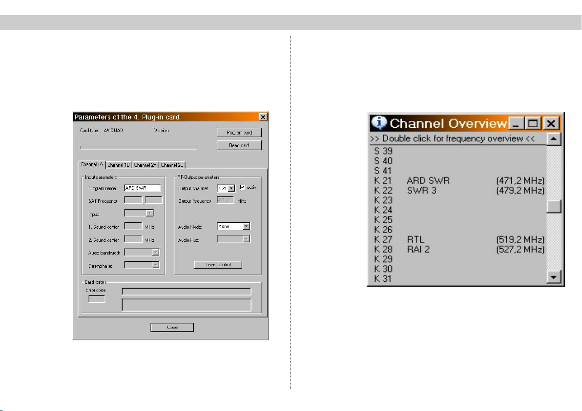
Programming with the HE programming software
. . . . . Page 5
4
Programming with the KC3
. . . . . . . . . . . . . . . . . . . . . Page 7
4.1
Structure
. . . . . . . . . . . . . . . . . . . . . . . . . . . . . . . Page 7
4.2
Moving between menus
. . . . . . . . . . . . . . . . . . . . Page 8
4.3
Entering parameters
. . . . . . . . . . . . . . . . . . . . . . . Page 8
4.4
Saving
. . . . . . . . . . . . . . . . . . . . . . . . . . . . . . . . . Page 8
4.5
Programming the card-specific parameters
. . . . . . Page 8
5
PIN allocation
. . . . . . . . . . . . . . . . . . . . . . . . . . . . . . . Page 9
6
Technical data
. . . . . . . . . . . . . . . . . . . . . . . . . . . . . . . Page10
7
Short-overviev of programming steps
. . . . . . . . . . . . . . Page11
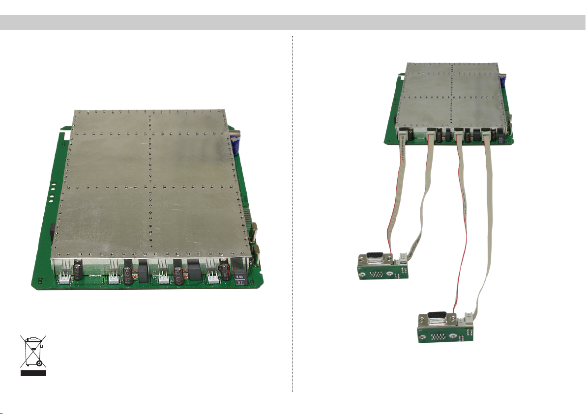
1 Description
The X-A/V quad is used to modulate four audio and/or
video sources and convert them into standard TV signals
in the frequency range from 47 – 862 MHz. The card has
two output converters which belong together, which
means that up to four A/V signals can be processed in
pairs and converted to two pairs of adjacent channels. All
four output channels can be switched on and off inde-
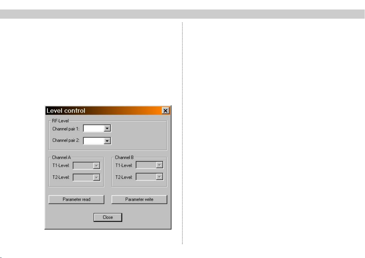
pendently of each other. The levels of the individual
boards are equalized via the HE programming software
or the KC 3 handheld programming device. The X-A/V
quad can only be used in combination with the V16 and
X-8 twin base units, as these have the necessary moun-
ting hardware for the input jacks (a full complement of X-
A/V quads can only be installed in combination with the
V16.13/X-8 twin base unit, otherwise a maximum of only
two X-A/V units is possible).
The video signals which are to be fed in must comply
with the FBAS standard (PAL/CCIR 405-1) and have a
level of 1 Vpp. It is extremely important to ensure that
this level is met exactly, as no level control is provided.
In addition, when setting up the plug-in card and starting
to use it for the first time, make sure that all channels
have the same output level and that they are matched
to any existing systems.
Please note:
These modules must only be replaced or exchanged
by an authorized specialist who has been certified
by the Chamber of Commerce and Industry (master
workshop). The hazard warnings and safety precau-
tions contained in the operating instructions of the
base unit and the relevant safety regulations accor-
ding to DIN VDE regulation 0701, part 1 and 200,
must be followed.