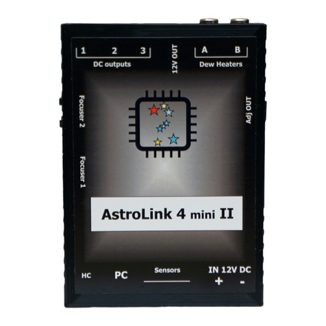
astrojolo AstroLink 4 USB User manual

AstroLink 4 USB manual - @2021 astrojolo.com
1
Rev. 1.3
AstroLink 4 USB
astrojolo.com @2021
WARNING!
Do not connect or disconnect stepper motor when power is on. It may
damage stepper motor controller.
Make sure the stepper hold torque is set to 0% before replacing stepper
motor with motor of different type.

AstroLink 4 USB manual - @2021 astrojolo.com
2
Rev. 1.3
Main features:
•focuser motor control for Robofocus, Moonlite, or generic unipolar or bipolar stepper motor
•1/8 and 1/32 micro-stepping control with 1.5A maximum current
•advanced temperature compensation with scripting support and compensation calculator
•permanent focuser position –no need to park focuser after the session
•2 adjustable PWM power outputs to control dew heaters, telescope fans, or custom Peltier
coolers. The maximum load is 40W per output
•3 switchable power outputs to power mount, cameras, or filter wheels. The maximum load is
5A per output
•1 additional permanent power output
•1 additional regulated 5V output (maximum load for connected USB devices and additional
5V output cannot exceed 3A). This output voltage is galvanically isolated from the input
voltage.
•XT60 high current input voltage socket
•temperature/humidity/sky temperature/sky brightness sensors to monitor environmental
conditions and calculate the dew point. It is also used for automatic control of dew heaters
•monitor voltage, current consumption, and total energy consumed during the session –
useful when working in the field with a battery
•user-defined alerts for voltages, current, energy, and temperature changes conditions
•programmable overcurrent and overvoltage protection
•integrated USB 3.0 hub with galvanically isolated power supply (three outputs available)
•opto-isolated USB 3.0 input
•dedicated AstroLink 4 panel software, ASCOM drivers available, INDI available
Technical data
•dimensions: 162x92x29mm
•weight: 215g
•the maximum current drawn from all outputs: 10A
•AstroLink power consumption: 2W max
•Regulated PWM outputs: 40W max
•Permanent 12V DC output: 5A max
•Switchable 12V DC outputs: 5A max
•Focuser stepper motor output: RJ12 6 pin, 1.5A max
•5V DC output: 3A max total with USB hub outputs, galvanically isolated from the analog part
•Sensor inputs: RJ11 4 pin I2C digital interface
•Auxiliary input: RJ11 4 pin input
•USB input: USB3.0 opto-isolated from analog part

AstroLink 4 USB manual - @2021 astrojolo.com
3
Rev. 1.3
Device overview
Integrated USB 3.0 hub
The USB 3.0 hub integrated into the AstroLink device is a standard 4 port hub based on the Realtek
chipset. One of its outputs is used internally to provide the data stream to the AstroLink processor.
Hub is supplied with a galvanically isolated regulator. The data stream between the hub and
AstroLink processor is separated by the optoisolator. This way analog and digital parts are completely
separated and ground loops risk are minimal.
Hub input and outputs are USB2.0 compatible, so there is no need to use fat USB3.0 cables if you
connect USB2.0 peripherals –cameras, mounts, or other accessories.
Hub is not guaranteed to work with all peripherals. It is especially valid for astronomy dedicated
cameras, which are known to cause conflicts when connected to the same USB hub. Several steps
can be taken to make things work: replace USB cables with shorter or better quality, use the latest
camera drivers, connect the hub to another port in the computer, adjust camera driver settings (USB
traffic), update the operating system, update computer hardware drivers. If all that fails then the
problematic camera needs to be connected to the computer using a separate data cable.
Permanent 12V DC output
This output is connected directly to the input 12V XT60 socket. Can be used to provide power to a
mini PC or other device powered with 12V.
5V DC output
This output provides regulated 5V DC voltage from a galvanically isolated internal regulator. This is
the same voltage that powers an integrated USB hub. All 5V receivers (including the ones connected
to the hub) can consume 3A max. You can use this voltage to power a mini PC, RPi, or other device
powered with 5V.
Sensors
AstroLink 4 USB has two equivalent sensor inputs, so you can plug any available sensor into any
socket and it will be recognized and properly assigned. Connecting three sensors (two
temperature/humidity and one sky temperature) requires an additional sensor bus splitter.
WARNING!
Do not connect or disconnect stepper motor when power is on. It may
damage stepper motor controller.
Make sure the stepper hold torque is set to 0% before replacing stepper
motor with motor of different type.

AstroLink 4 USB manual - @2021 astrojolo.com
4
Rev. 1.3
External view

AstroLink 4 USB manual - @2021 astrojolo.com
5
Rev. 1.3
1. 12V DC input –XT60 socket
2. 12V DC permanent output
3. 12V DC switchable outputs
4. 5V DC regulated output galvanically
isolated from the analog part
5. USB3.0 hub outputs
6. LED indicator
7. USB3.0 input optoisolated from analog
8. AUX input
9. Sensors inputs
10. RJ12 focuser stepper motor output
11. PWM regulated power outputs

AstroLink 4 USB manual - @2021 astrojolo.com
6
Rev. 1.3
Panel overview
AstroLink 4 panel contains several control sections. Most of the area is occupied by different
controller sections, which will be described later on. Below the control section, several other controls
are available.
Stay on top checkbox makes the AstroLink panel not go to the background when another application
is selected.
Buzzer checkbox controls buzzer activity.
Menu
A small cogwheel menu contains shortcuts to all other settings menu windows, so they can be also
opened from here. There is one additional position in this menu:
•Manual control. You need to check this field when you have connected the manual control
box to the AstroLink device
•Compensation calculator. This option opens an additional popup window with the
compensation calculator. See the Compensation calculator section for details
•Reset device to factory defaults - this option will reset all device settings to factory default
values. The confirmation window will be opened.
•Settings Load.../ Save... - these options allow us to save or load all device settings and
configurations. All settings, labels, initial PWM, and power output values can be stored.

AstroLink 4 USB manual - @2021 astrojolo.com
7
Rev. 1.3
Status bar
The status bar displays several different information that is visible depending on the context. It is a
read-only field.
Charts and notes
Notes panel - after clicking on this button small editor will popup, where you can note down some
information you need during the imaging session (like focuser positions, flat images exposure time,
etc.). Its content is saved dynamically.
Charts button opens an additional window with AstroLink charts. See the AstroLink charts section for
details.
Logo icon
After clicking on the logo icon a small information window will pop up. It contains information about
firmware and software versions.
Connection controls
The panel can communicate with the device in two modes. The first one is DIRECT connect - then the
panel connects directly to the device and no other interface can control any of the device
components at the same time. The second communication mode is ASCOM connect. In this mode,
the panel connects to the device using the installed AstroLink 4m Focuser driver, and as this driver is
a part of a multi-driver Local Server instance many other applications can control any of ASCOM
interfaces at the same time.
DIRECT connect
After selecting DIRECT connect and clicking on Settings button Direct connect settings popup will
open. Then you need to select the proper COM port where the AstroLink device is connected and
detected. After selecting the port you can click Test port to make sure the device is connected
properly. After clicking the Save button settings will be saved and the software will connect to the
AstroLink device each time using the selected port.
There is another option in the window called reset AstroLink on connect. When this field is checked
each time the connection to the device is established AstroLink will reset, so its state will be restored
to the power-on state. It can be useful in case when AstroLink is not responding and you work
remotely and cannot switch it off and on. In all other cases, it is recommended to keep this field
unchecked.
ASCOM connect (recommended)
After selecting ASCOM connect and click on the Settings button ASCOM Focuser Chooser window will
open. You need to select the AstroLink 4m Focuser interface and then click the Properties button, so
the ASCOM connection setup window will open. Here you need to select the COM port where the
AstroLink device is connected. This driver is for all members of the AstroLink 4 family, that is why you
also need to select connection speed. For AstroLink 4 USB it is 38400 bps. You can also test the

AstroLink 4 USB manual - @2021 astrojolo.com
8
Rev. 1.3
connection using the Test port button. When the trace check-box is checked ASCOM log file will be
written with all communication between the device and any software - it can be useful to investigate
errors. Reset AstroLink on connect works in the same way as in DIRECT connect mode.
There is one more setting available for the ASCOM driver. Under the cogwheel menu in the lower-left
corner, there are ASCOM Profile settings. There you can adjust sky temperature cloud coverage
mapping points that correspond to clear sky and maximum cloud coverage, and set names for DC and
PWM outputs that will be visible in ASCOM Switch client software.
Both connection modes offer the same functionality. The only difference is that DIRECT connect
works exclusively, so no other software than the panel can communicate with the device. ASCOM
connect mode allows other 3rd party software to operate with the device at the same time - see 3rd
party software section.
Connection status
Small indicator field with selected COM port number and light. Gray means not connected, green
means connected, red means active communication.

AstroLink 4 USB manual - @2021 astrojolo.com
9
Rev. 1.3
Focuser section
The focuser position in mm is calculated based on the focuser position in steps and step size defined
in settings.
The coarse relative movement factor can be set in settings between 2 and 10.
The motor status icon may be in three colors: red means the motor is rotating, blue means the motor
is idle but holding current is applied, and green means idle and no holding current is applied.
Temperature compensation and focuser settings are described below.
Max. focuser position - here you need to enter the maximum focuser position, so the focuser will not
move to any larger value. This is to prevent any mechanical damage to the focuser.
Step size [um] - this value is stored in the driver and can be provided to any 3rd party software when
requested. It is not used internally in AstroLink.
Reversed - you can check this box when to select proper behavior of the focuser, so decreasing the
focuser position will cause the focuser tube to move into the telescope
Backlash [steps] - this is for focuser motor backlash compensation. You may enter here backlash
value that will be applied to focuser moves to cancel the stepper motor gearbox backlash. This value
may be positive or negative. A positive value means, that backlash compensation will be applied for
outward moves, and a negative value will be applied to inward moves. This compensation is applied
only when the motor is controlled with the AstroLink panels button. When you use 3rd party
software for focusing (FocusMax, MaxIm DL, and others) use this software backlash compensation!
Display motor graphics –toggles displaying stepper motor status icon

AstroLink 4 USB manual - @2021 astrojolo.com
10
Rev. 1.3
Preset –select any of the predefined settings for common motor parameters. Other fields at this tab
will be filled with values, but settings will be saved after the Save button is pressed.
Speed [pps] - focuser stepper speed in pulses per second. You need to select the appropriate value,
so the focuser will move with reasonable speed, but no steps will be lost during the move. For
popular unipolar stepper motors with a 7.5-degree step, it should be usually no more than 120-150.
Bipolar steppers with a 1.8 degree step usually can operate at a faster rate, up to 400-500pps. Micro
stepping can operate at rates up to 2000pps.
Acceleration [pps/s] - each time stepper starts to move, it accelerates to the speed selected in the
field Speed. Here you can enter the acceleration value. So for example, when the selected speed is
300pps, and you select an acceleration value for 600, then the stepper will accelerate to maximum
speed in 0.5 seconds. This value is also used for manual stepper control, but acceleration is divided
by 5 for this purpose, so it is possible to do small manual corrections.
Motor current [A] –this is the current limit set to the motor. Refer to your motor technical data to
set proper current. For 12V unipolar geared motors offered in shop.astrojolo.com set it to 0.4A or
use preset.
Hold torque [%] - when this is selected to any value greater than zero, the stepper motor will be
powered when stopped. It can then provide additional holding torque to your focuser, however
more current will be drawn, and motor temperature will increase. Make sure the stepper motor you
use is designed to be powered constantly if you want to use this option.
Stepper type - can be selected between Unipolar (like Robofocus compatible) or Bipolar motor full or
half step motors. It can be also bipolar motor controlled with micro-steps –two options 1/8 and 1/32
stepping are available.
Enable compensation - switch compensation on or off
Compensation steps [steps/C] - this is the number of steps the focuser will move when the
temperature will change from the initial value. So if you put here 35 and the temperature will drop
2C, then the focuser will move 70 steps (outwards). This value usually must be determined
practically, so you can note focuser positions over long night session together with corresponding
temperatures, and then calculate this coefficient
Auto compensation threshold [steps] - when compensation mode is set to AUTO and the calculated
compensation error will exceed this value, then compensation will be automatically applied
Compensation sensor - here you can select the sensor that will be used for temperature
measurements for focuser compensation
Compensation mode. When set to MANUAL the calculated compensation will be displayed in
Compensation difference window, however, no compensation will be performed - it must be
triggered manually with the Compensate button (or using script - see Temperature compensation
section). When this option is set to AUTO then manual compensation will still work, but it will also be
performed automatically each time when calculated compensation error will exceed the Auto
compensation threshold value

AstroLink 4 USB manual - @2021 astrojolo.com
11
Rev. 1.3
Set focuser position - you can set any desired focuser position to calibrate it. Usually, it will be used to
set a zero position. For this case you need to move the focuser tube inwards as much as possible,
then enter 0 value into the field and press the Set position button

AstroLink 4 USB manual - @2021 astrojolo.com
12
Rev. 1.3
PWM section
PWM output value can be set between 0 and 100%. HEAT option controls value automatically basing
on current relative humidity. AUTO option controls value automatically to keep Sensor #2 at a given
temperature.
The first tab Labels contains labels for each PWM output, so it can be set for example to 'OTA dew
cap'or 'Guider cooling'. Another two select boxes determine the startup state of PWM outputs. Any
value set here will be set up to PWM output after power is on.
Second tab Automated contains parameters used when HEAT or AUTO option is selected for PWM
output:
Heat power at max humidity [%] –select here the heating power when relative humidity reaches
100%. If your heater has correct power you may enter here 100%. But when your heater is oversized,
you may put here a lower value.
Temperature preset [C] - PWM output power will be adjusted to keep the selected sensor at the
given temperature
Control direction - when the output should increase with increased value (DIRECT) or should decrease
with increased measured value (REVERSED)
The last tab is Frequency. Here there is only one select box where you can change the frequency of
PWM output. It is usually the best approach to select the highest 31kHz frequency - this frequency is
not audible by humans and also requires low-value LC filtering elements if you want to use it. But
some receivers may not work well with such high frequency, and then it needs to be adjusted down.

AstroLink 4 USB manual - @2021 astrojolo.com
13
Rev. 1.3
Power section
The power section helps to monitor power conditions. It displays voltage, current, and energy
consumption. Under the settings button, there are some more options related to alerts and
protection.
Input voltage - this field displays the current supply voltage value
Total current - this field displays current drawn by the device and all attached gears from the power
supplier (also USB devices connected to the integrated hub)
Energy consumed - these two fields display energy consumed from the power source since the
moment device has been powered on or reset. This information can be used to monitor energy when
powering in the field from a battery
When any of the alert values are close to the defined limit corresponding field becomes orange.
When any of the alert values exceeded the limit, the corresponding field becomes red. Additionally, if
a system sound alert or device buzz alert is enabled there will be an audible sound alert.
Total current warn level - when the total current will exceed this value, an alert will be triggered
Energy warn level - when energy consumed from the power supplier will exceed this value alert will
be triggered
Low input voltage warn - when input voltage will decrease below this value alert will be triggered
High input voltage warn - when input voltage will increase over this value alert will be triggered
also buzz with device buzzer - when one or more alerts is triggered there will be a sound signal
emitted from the AstroLink device

AstroLink 4 USB manual - @2021 astrojolo.com
14
Rev. 1.3
also alert with system sound - when one or more alerts is triggered there will be a system sound alert
played in the computer
Overvoltage protection level [V] - when input voltage will exceed this level for a time longer than
specified as protection sensitivity time all PWM and DC outputs will be switched off
Overcurrent protection level [A] - when total output current will exceed this level for a time longer
than specified as protection sensitivity time all PWM and DC outputs will be switched off
Protection sensitivity [ms] - the delay between protected condition and the moment the PWM and
DC outputs will be switched off
V in. ADC coefficient - this is the voltage of the internal reference source of the device. It should be
1.1V in the perfect world, however, this source is not so precise. There is a real reference voltage
value printed in the box, but if you notice that measured in the panel voltage differs from the real
voltage value you may adjust this coefficient.
Calibrate AstroLink current sensor. Every time you adjust the ADC coefficient also current sensor
needs to be calibrated. To do it you need to disconnect all receivers from the AstroLink device and
click this button. After a moment current sensor will be calibrated.

AstroLink 4 USB manual - @2021 astrojolo.com
15
Rev. 1.3
Sensors section
Sensors and PWM sections are separate ones, although they work together to provide some
combined functionalities. The sensors section contains four read-only fields that labels may be
changed. Sensor sockets in AstroLink are equivalent, so it does not matter where you connect the
given sensor. The temperature/humidity sensors enclosures are numbered, and the sensor marked
with 2 will be displayed in the #2 column in the panel. Sky brightness sensor refresh rate depends on
the actual sky brightness. Darker sky requires longer integration time. Up to 30s for 21 mag/arcsec2
sky, or up to 60s if darker.

AstroLink 4 USB manual - @2021 astrojolo.com
16
Rev. 1.3
In the tab called Alerts you can set temperature change monitor parameters:
Enable temperature alert - here you can enable or disable temperature alerts
Temp. change sensor - it is the sensor that temperature is taken to monitor its value. Make sure the
selected sensor is connected to the device
Temp. change warning - it is the difference between the current temperature and start temperature
that causes an alert to be triggered. When the temperature difference is close to this value, the
temperature window becomes orange. When the limit is reached, the temperature window becomes
red and alerts are emitted (if activated)
also buzz with device buzzer - when the temperature change limit is reached alert signal will be
emitted from the AstroLink device buzzer
also alert with system sound - when the temperature change limit is reached system alert sound will
be played
Enable sky temperature warning - when the difference between sky and ambient temperature drops
below the specified threshold alert will be triggered. It usually indicates a scenario, when the sky is
covered with clouds
Cloud sensor tab contains threshold levels that change the icon representing sky conditions. Default
values 8, 12 18 and 25 degrees are usually suitable for the average location. However, if the sensor is
used in specific conditions (desert, mountains, lake, or river proximity) these threshold levels may
need to be adjusted.
Third tab called Icons controls the displaying of environmental status icons.
Temperature icon source and Humidity icon source determines if icon color is controlled with values
that come from the first or second sensor, from the sensor that provides higher or lower value or
averages both sensor readings.
Display temperature icon toggles temperature status icon displaying
Display humidity icon toggles humidity icon displaying
Display cloud sensor graphics toggles displaying sky temperature status graphics
The last tab –SQM controls settings of the optional sky brightness sensor. Numeric fields are used
for the sensor reading calibration. If you want to calibrate the sensor to a reference sky brightness
sensors, usually it is enough just to determine offset. If after applying the offset there are still
significant differences between the sensors, please contact us, so we can analyze the case and
provide a way to determine Coefficient parameter.
Offset –the difference between the AstroLink sensor reading and reference sensor reading
Coefficient –second parameter that controls sensor calibration
Reset sensor –reset sky brightness sensor parameters to the factory defaults (confirmation window
will popup)
Dark calibrate –determines the dark signal of the sensor that will be then applied to sensor readings.
Process requires sensor cover and no stray or ambient light available. It may take up to three minutes
(confirmation window will popup).

AstroLink 4 USB manual - @2021 astrojolo.com
17
Rev. 1.3
12V output section
The second section is called the 12V output. Here we have three check-boxes that control DC outputs
where you can connect supply voltage to peripheral devices like mounts, cameras, or filter wheels.
Lock outs check-box can be checked and then three boxes above will be locked (not clickable). This
way you can prevent accidentally turning on or off any of the connected devices.
Under the cogwheel button settings windows is hidden. There are not many options, however. You
can label each power output, so it can have a meaningful name like 'Mount' or 'CCD main camera'.
On the second tab, there are three check-boxes that control power-on behavior. If the check-box is
checked then the corresponding output will be on after turning on the power or resetting the device.

AstroLink 4 USB manual - @2021 astrojolo.com
18
Rev. 1.3
AstroLink charts
AstroLink charts are the tool that allows you to monitor the following data that is collected by the
AstroLink device:
•temperature, humidity, and dewpoint measured by connected sensors
•sky temperature and the difference between sky and ambient temperature (if the sky
temperature sensor is connected)
•focuser position in steps
•PWM outputs power in %
•switchable DC outputs states
•input voltages value
•total current draw
•total energy consumed
Charts start to collect data at the moment AstroLink panel software connects to the AstroLink device.
You can open the charts window by clicking the corresponding button in the lower-left of the panel.
After opening the charts window the default view is opened - that is a mixed plot of the temperature
and focuser position. The chart scale is calculated automatically. You can zoom any selected chart
range by selecting it with a mouse. Then the scroll bar will appear, so you can pan the graph. To
cancel zoom you need to press a small button on the left side of the scroll bar. After clicking with the
right mouse button in the chart area the context menu will be opened. In this menu following
options are available:
•the first five options can be used to switch between different views of plots that present
different data in a combined way

AstroLink 4 USB manual - @2021 astrojolo.com
19
Rev. 1.3
•Export as image - this option saves the current graph as a PNG image in the folder selected
by the user in the dialog. The saved image will contain exactly what is visible on the chart
•Collect data to file - this checkbox indicates if data is saved to the file. This is checked on by
default, and data files are saved in My Documents/AstroLink folder. Saved files may be later
imported for example to an Excel sheet and processed
•Data collection period - here you can set the time span of the graph. If the new selected
period is shorter than already collected data, then data will be truncated. This setting does
not affect data collected in files.
•Data collection sampling rate - you may choose here how often data should be collected.
Actual data is always sampled two times per second. This setting determines how many
samples are averaged to create data points in the chart. Recommended values are 5 or 10
seconds unless you need to have it collected more often.
•Clear all collected data - clicking here causes all data in the chart to be cleared. It does not
affect data collected in files.

AstroLink 4 USB manual - @2021 astrojolo.com
20
Rev. 1.3
Overcurrent and overvoltage protection
AstroLink panel contains settings to provide overcurrent and overvoltage protection. Both input
voltage and total output current are monitored 200 times per second and measured values are
compared to user settings. If any of these values exceeds settings for some specified time (also
configured by the user) then all PWM and DC outputs will be switched off. Default protection settings
are:
•voltage: 14.0V. It is also the maximum allowed input voltage for AstroLink device
•current: 10.0A. It is the maximum output current that the AstroLink device can handle safely
•protection sensitivity: 100ms
Overvoltage setting
The value here should be adjusted to the voltage that our power supply provides. If we use a
regulated 12V power supply, then a reasonable value here could be 12.5 or 13V. For 13.6V regulated
voltage, we can stay at the default value of 14V.
Overcurrent setting
This preset should be adjusted to the receivers that we power from AstroLink. If we have a mount
that drains 2A when doing GoTo, a camera that drains 2.5A at maximum cooling power, and a dew
cap heater that consumes 1.5A, then the maximum current will be 6A. Plus some current for focuser,
and then 7A can be reasonable value for such configuration. Probably it is the best way to monitor
the actual total current drawn in AstroLink panel software during one session, and then determine
overcurrent value basing on this. You can use charts for this and look for maximum power
consumption.
Protection sensitivity setting
When either overcurrent or overvoltage occurs, the device is waiting for this amount of time and
checks if this condition still occurs. If so, then an alert is triggered. However if during this time
overcurrent or overvoltage will end, then no alert will be triggered. Usually, it is the best approach to
set a short time, however, it is not always possible. When the receiver connected to AstroLink (like
mount or camera) consumes much power at the moment it is switched on, then this protection
sensitivity time may be increased. But it is recommended to keep this setting low, like 30 or 50ms.
Table of contents
Other astrojolo Power Supply manuals