manuals.online logo
Brands
  1. Home
  2. •
  3. Brands
  4. •
  5. ASTRUM
  6. •
  7. Touch Panel
  8. •
  9. ASTRUM INSPINA SLIM User manual

ASTRUM INSPINA SLIM User manual

This manual suits for next models

2

Popular Touch Panel manuals by other brands

Endress+Hauser ria45 operating instructions

Endress+Hauser

Endress+Hauser ria45 operating instructions

Wincomm WLP-7B20 Series user manual

Wincomm

Wincomm WLP-7B20 Series user manual

NEC ME Series user manual

NEC

NEC ME Series user manual

VIPA TP 606C CAN manual

VIPA

VIPA TP 606C CAN manual

Acnodes PC 1080 quick guide

Acnodes

Acnodes PC 1080 quick guide

Extron electronics TLP 700MV user guide

Extron electronics

Extron electronics TLP 700MV user guide

AMX AXT-EL Plus Dimensional drawing

AMX

AMX AXT-EL Plus Dimensional drawing

LEGRAND 67285 installation manual

LEGRAND

LEGRAND 67285 installation manual

FlowLine Data loop quick start

FlowLine

FlowLine Data loop quick start

ALPEX AEx-8 P Series user manual

ALPEX

ALPEX AEx-8 P Series user manual

Harman AMX MODERO S MSD-701-L2 quick start guide

Harman

Harman AMX MODERO S MSD-701-L2 quick start guide

ADT 6270ADT Installation and setup gude

ADT

ADT 6270ADT Installation and setup gude

Acnodes PC 1150 installation guide

Acnodes

Acnodes PC 1150 installation guide

AMX ViewPoint quick start guide

AMX

AMX ViewPoint quick start guide

AIS IP10IA99 series user guide

AIS

AIS IP10IA99 series user guide

IBASE Technology ASTUT-152-RE1S user manual

IBASE Technology

IBASE Technology ASTUT-152-RE1S user manual

YASKAWA TP 610C manual

YASKAWA

YASKAWA TP 610C manual

B&R Power Panel C Series user manual

B&R

B&R Power Panel C Series user manual

manuals.online logo
manuals.online logoBrands
  • About & Mission
  • Contact us
  • Privacy Policy
  • Terms and Conditions

Copyright 2025 Manuals.Online. All Rights Reserved.

INSPINIA TOUCH PANELS
Version INS-QI02-201911
www.inspinia.eu
QUICK INSTALLATION GUIDE
7” 10” 7” 10” 10”
SLIM VITRE GRAND
MOBILE APP
Download INSPINIA mobile app from
App Store or Google Play to your
mobile device.
Make sure that INSPINIA is connected
to the network and has internet
access.
Unique device ID and QR-code will be
generated on settings page.
Press add button and scan
QR-code on your mobile app.
Define a name and save your
settings. You are ready!
SETTINGS
IP ADDRESS: 192.168.2.100
VERSION: 6.1.4
SUBNET: 255.255.255.0
FEATURES & FUNCTIONALITY
Web
Programming
Network Switch
DIGITAL I/O PORT 1
VRV/VRF
Shutter
SwitchThermostat
Outdoor
Unit
Indoor
Unit
Indoor
Unit
Indoor
Unit
Actuator
Security Console /
IP Phone
IP Intercom
IP Camera
Bell
Valve Motion
Sensor
Fire
Sensor
• News
• Messages
• Shortcuts
• Dashboard Logo
• Ambient Temperature
Menu Bar
• Dashboard
• Smart Home
• Scenarios
• Intercom
• Security
• Concierge
• Camera
• Settings
1Information Bar
• Date
• Time
• Traffic
• Weather
2Speakers
4
Microphone
5
Dashboard
3
12
3
5
44
PRODUCT OVERVIEW DIMENSIONS
FRONT
SIDE
BACK
307mm10” 243mm7”
287mm10” 223mm7”
287mm10” 223mm7”
194,6mm10”
149mm7”
61mm10”
61mm7”
174,6mm10”
129mm7”
LAN PORT 2
KNX/SCS/NIO
Adjust slot for
perfect fit
10mm
FLUSH-MOUNTING
wallbox
panel
Thickness
3.8mm
wall
Box must align
the wall vertically
FLUSH MOUNTED BOX
Inspinia Inspinia
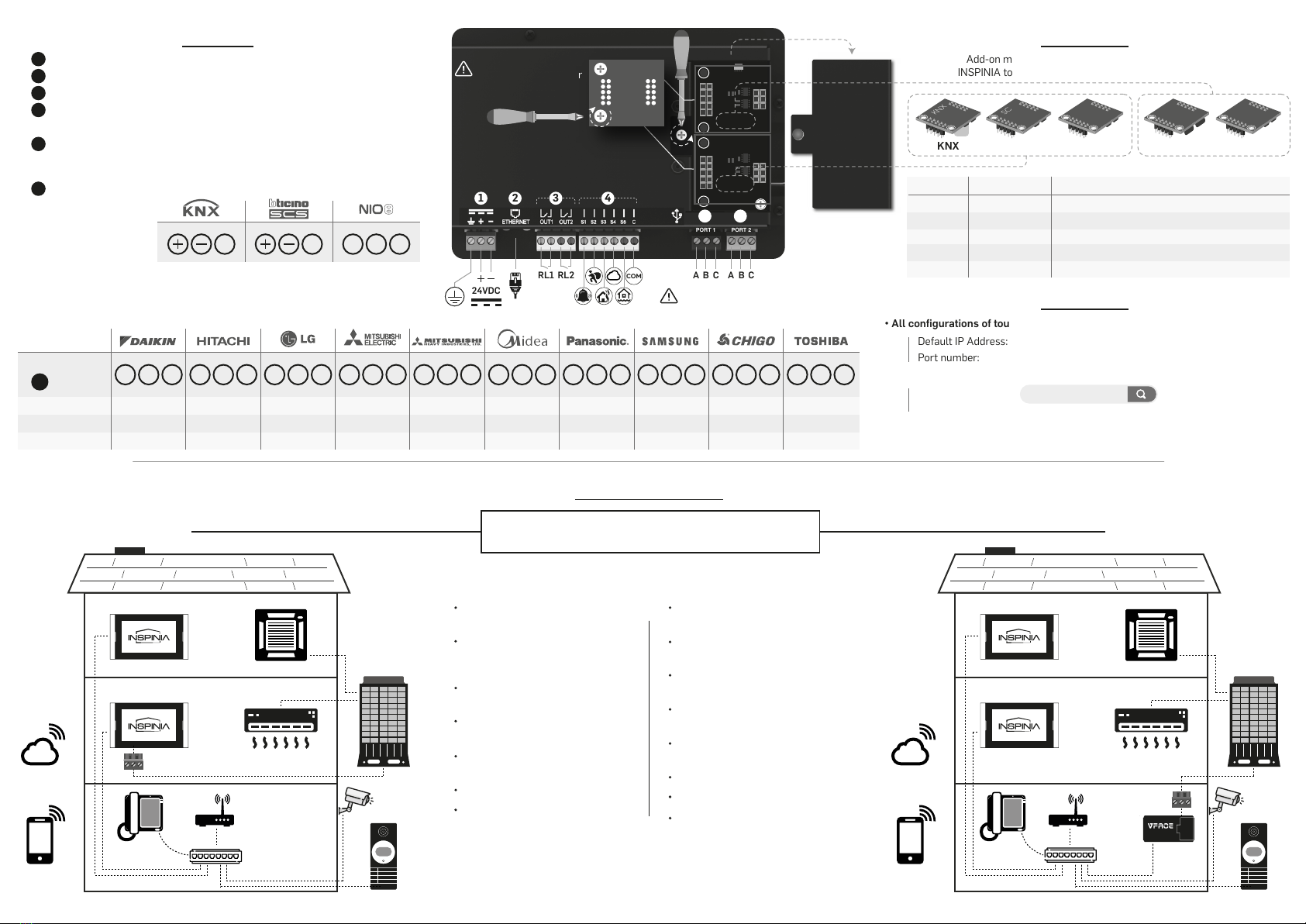
Power Supply: 12V/24V 2A (DC)
Ethernet: 10M/100M/1000M (IEEE 802.3)
Outputs (O1-O2): Relay 24V, 2A (DC)
Inputs (I1-I5): Digital Inputs: bell, motion, gas, flood sensors,
magnetic contact
Port 1 Connector: VRV/VRF Bus connection & Relay
Port 1: Port for VRV/VRFand Relayadd-on modules
(VRM, VRR, RLY)
Port 2: Port for BMS add-on modules (KNX, SCS, NIO)
Port 2 Connector:
HVAC Unit Connections
Each brand of HVAC have different communication terminals on outdoor unit.
Please check below table for terminals connections.
• Default Security Password: 1234
• For more detail please check for Programming_Guide.pdf visit www.astrum.eu
Add-on modules can be plugged to extension ports of
INSPINIA to provide a various combination of connectivity.
• All configurations of touch panel can be made through web interface.
Default IP Address: 192.168.2.100
Port number: 8080
CONNECTIONS
1 2 3 4
1
RL1
24VDC
CA B CA B
2
3
4
5
6
RL2 COM
CONFIGURATION
OPERATION MODE
• Enter IP address and port number to web browser.
Example:
Username: admin Password: 51GX19MH
KNX
KNX
SCS
SCS
NIO
NTP
VRV/VRF
VRM
RELAY
R LY
PORT 2PORT 1
PORT 1 PORT 2
-
-
VRV/VRF
RELAY
RELAY
-
KNX/SCS/NIO
KNX/SCS/NIO
-
KNX/SCS/NIO
IP Intercom
IP Intercom + Automation
IP Intercom + Automation + VRV/VRF
IP Intercom + Additional Output
IP Intercom + Automation + Additional Output
OPERATION MODE
BRAND
Comm. Line
Indoor Unit
Outdoor Unit
TCC LINK
64
16
INTER A B
128
NO SUPPORT
M NET (TB3/7)
50
10
64
16
S3 NET
64
NO SUPPORT
64
16
64
16
TCC LINK
64
NO SUPPORT
S SLINK I / II
64
NO SUPPORT
D3 NET
64
16
192.168.2.100:8080
HVAC VRV/VRF SOLUTIONS
1. MODULE
1. MODULE 2. VFACE
2. VFACE
There are two options of monitoring and controlling
VRV/VRF units on INSPINIA:
VRV/VRF add-on module must be
plugged to INSPINIA Port 1
Port 1 connector will be directly
connected to VRV/VRF Outdoor
Unit
Control of Indoor unit available
only on one INSPINIA Panel
Provides full functionality of indoor
unit on INSPINIA Panel
Indoor units can be controlled by
KNX and MYHOME Thermostat
Supports up to 64 indoor units
Full control on indoor unit
functions
VFace Basic or VFace Touch is
required and need to be installed
No direct connection to Outdoor
Unit with Port 1
Provides full functionality of indoor
unit on INSPINIA Panel
VFace lets up to 16 simultaneous
connection of INSPINIA
Indoor units can be controlled by
KNX and MYHOME Thermostat
Supports up to 64 indoor units
Full control on indoor unit functions
VFace communicates touch panels
through IP
PORT 1 Connector
VRF
Outdoor Unit
Smart
Console
IP Intercom
Network
Switch
Router
Cloud
Mobile
App
IP
Camera
VRF
Outdoor Unit
Smart
Console
IP Intercom
Network
Switch
Router
Cloud
Mobile
App
IP
Camera
BASIC
PORT
Port 1
connector
F1 F2 1 2 A B M1 M2 A B X Y E U1 U2 X Y E U1 U2
5
Terminal Name A B C A B C A B C A B C A B C A B C A B C
F1 F2
A B C A B C A B C
5 6
A B C A B C
A B G
A B C
PORT 1
PORT 2
PSU24-D, PSU24-R
The add-on modules
must be screwed after
they are installed in
the port slots.
Warning! You may damage add-on
modules if you make any wrong
connection to the ports.