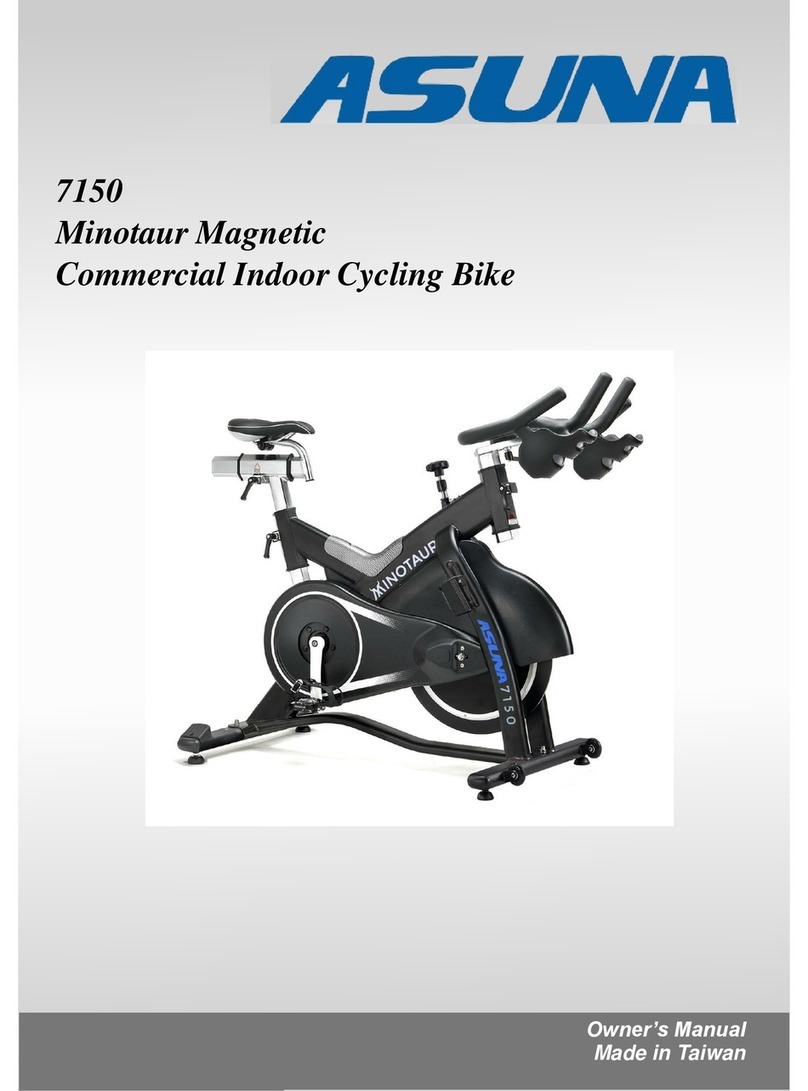
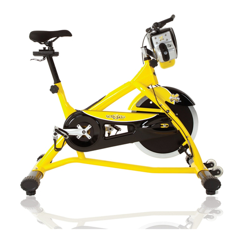
ASUNA 7150 Minotaur User manual

7150
Minotaur Magnetic
Commercial Indoor Cycling Bike
Owner’s Manual
Made in Taiwan
7150
Minotaur Magnetic
Commercial Indoor Cycling Bike


INDEX
IMPORTANT SAFETY INFORMATION ..................................................................... 1
EXPLODED DRAWING ............................................................................................. 2
PARTS LIST................................................................................................................ 3
ASSEMBLY INSTRUCTION.....................................................................................4-9
USER INSTRUCTION .............................................................................................. 10
MAINTENANCE ....................................................................................................... 11
ATTENTION:
Please verify that all parts associated with this product are in good condition
and accounted for.
During the assembly process, please be sure to follow each step accordingly, as it has been explained
within this manual.
WARNING: During assembly, it is recommended that all bolts be tightened by hand. Upon completing
assembly, bolts should be secured using the wrench provided. To avoid injury, check bolts carefully before
use.
IMPORTANT
:
Read all instructions carefully before using this product. Retain owner's
manual for future reference. For customer service, please contact:
support@sunnyhealthfitness.com

IMPORTANT SAFETY INFORMATION
We thank you for choosing our product. To ensure your safety and health, please use this
equipment correctly. It is important to read this entire manual before assembling and using
the equipment. Safe and effective use can only be achieved if the equipment is assembled,
maintained and used properly. It is your responsibility to ensure that all users of the
equipment are informed of all warnings and precautions.
1. Before starting any exercise program you should consult your physician to determine if
you have any medical or physical conditions that could put your health and safety at risk,
or prevent you from using the equipment properly. Your physician’s advice is essential if
you are taking medication that affects your heart rate, blood pressure or cholesterol level.
2. Be aware of your body’s signals. Incorrect or excessive exercise can damage your health.
Stop exercising if you experience any of the following symptoms: pain, tightness in your
chest, irregular heartbeat, and extreme shortness of breath, lightheadedness, dizziness
or feelings of nausea. If you do experience any of these conditions, you should consult
your physician before continuing with your exercise program.
3. Keep children and pets away from the equipment. The equipment is designed for adult
use only.
4. Use the equipment on a solid, flat level surface with a protective cover for your floor or
carpet. To ensure safety, the equipment should have at least 2 feet (60cm) of free space
all around it.
5. Ensure that all nuts and bolts are securely tightened before using the equipment. The
safety of the equipment can only be maintained if it is regularly examined for damage
and/or wear and tear.
6. Always use the equipment as indicated. If you find any defective components while
assembling or checking the equipment, or if you hear any unusual noises coming from the
equipment during exercise, discontinue use of the equipment immediately and do not use
until the problem has been rectified.
7. Wear suitable clothing while using the equipment. Avoid wearing loose clothing that may
become entangled in the equipment. Do not use bike without shoes, or with loose shoes.
8. Do not place fingers or objects into moving parts of the exercise equipment.
9. The maximum weight capacity of this unit is 330 pounds (150kgs).
10. The equipment is not suitable for therapeutic use.
11. Please take proper precautions when lifting and moving the equipment. Always use proper
lifting technique and seek assistance if necessary.
12. For all adjustable parts be aware of the maximum position to which they can be adjusted.
13. Be aware of non-fixed or moving parts while mounting or dismounting the bike.
14. We take no responsibility for personal injury or damage sustained by or through the use
of this exercise bike.

Exploded Drawing

No.
Name
QTY
No.
Name
QTY
1
Seat
1
40
Plastic washer
3
2
Alloy bind clamp ( L )
3
41
Fixed bolt
3
3
Spring
3
42
Seat post
1
4
Alloy bind clamp ( R )
3
43
Seat slider
1
5
Washer
3
44
Washer
3
6
L-Shaped Knob 1
3
45
Belt
1
7
Crank bolt
2
46
Spring
1
8
Nut
4
47
Outer chain guard bolt
5
9
Washer
4
48
Outer chain guard bolt M5
4
10
Bolt
4
49
Flywheel
1
11
Pedal
1PR
50
Bushing
6
12
End cap
4
51
Plate for screw
1
13
Adjuster pad
4
52
Idler w/bearing, clip
1
14
Rear stabilizer
1
53
Sprocket bracket for resistance knob
1
15
Flywheel security washer
2
54
Bolt for sprocket bracket
2
16
Flywheel adjuster screw
2
55
Belt pulley
1
17
L-Shaped Knob 2
1
56
Bolt
1
18
Front stabilizer
1
57
Connection bracket
1
19
Outer belt guard
1
58
Brake pad w/holder
1
20
Left crank arm
1
59
E clip w/fixed pin
1
21
Right crank arm
1
60
Screw & nut for brake pad
1
22
Handlebar post
1
61
Washer
4
23
Handlebar
1
62
Rubber cover for flywheel
2
24
Tension knob
1
63
Fixed plate for fender
1
25
Bottle holder bolts
2
64
Washer for fixed plate
1
26
Bottle holder
1
65
Bolt for fixed plate
1
27
Screw for plate
2
66
Screw for fixed plate
2
28
Flywheel security washer
1
67
End cap
1
29
Washer for L shape knob 2
2
68
Top protect cover
1
30
O clip for L shape knob 2
1
69
Rear foot tube cover
2
31
Flywheel security nut
2
70
Screw for foot tube cover
4
32
Left axle cover
1
71
Top protect cover bolt M5
2
33
BB bearing
3
72
Fender
1
34
BB Axle with plate
1
73
Flywheel adjuster plate
2
35
Flywheel axle
1
74
Washer for fender
2
36
Flywheel security nut cap
2
75
Screw for fender
2
37
Flywheel bearing
5
76
Rubber cover
1
38
Axle bolt for moving wheel
2
77
Screw for pulley
5
39
Transportation wheels
2
G01
Magnetic holder w/magnetic set
1
Parts list

STEP 1:
Attach the Front Stabilizer (No. 18) and the Rear Stabilizer (No. 14) to the Main
Frame (Y) using 4 Bolts (No. 10), 4 Washers (No. 9) and 4 Nuts (No. 8). Tighten and
secure using spanner wrench.
Assembly Instruction

STEP 2:
Loosen L-Shaped Knob 1 (No. 6) on main frame handlebar tube to remove insert
protect cap, then insert the Handlebar Post (No. 22) into the handlebar tube of the
Main Frame (Y). Adjust Handlebar Post (No. 22) to the desired height. Tighten the L-
Shaped Knob 1 (No. 6) to secure the Handlebar Post (No. 22) into position.
Slide the Handlebar (No. 23) onto the Handlebar Post (No. 22). Tighten the L-
Shaped Knob 2 (No. 17) to secure the Handlebar (No. 23) into position.
NOTE: To adjust the Handlebar (23) back and forth to the desired position, first loosen
the L-Shaped Knob 2 (17).
Assembly Instruction

STEP 3:
Insert the Seat Post (No. 42) into the seat tube located on the Main Frame (Y).
Insert the Seat Slider (No. 43) into the Seat Post (No. 42). Tighten the L-Shaped
Knob 1 (No. 6) to secure the Seat Slider (No. 43) in place.
Secure the Seat (No. 1) onto the post of the Seat Slider (No. 43). Tighten the seat
clamp screw to secure the Seat (No. 1) in place.
Use L-Shaped Knob 1 (No. 6) to adjust height of the seat, use L-Shaped Knob
1(No. 6) to adjust the seat back and forth.
Assembly Instruction

STEP 4:
Connect Pedals (No. 11) onto the Left and Right Crank Arms (No. 20 and No. 21).
(Before you begin, immobilize the crank arms by turning the tension control knob all
the way to the right).
NOTE: Pedals (No. 11) are marked, Lfor the (left pedal) and Rfor the (right pedal).
Left Pedal: align the left pedal, Pedal L (No. 11) with the Left Crank Arm (No. 20)
at 90 degrees. Gently insert the pedal into the crank arm, turn the pedal counter-
clockwise as tightly as you can with your hand. Tighten and secure with (15mm)
spanner wrench.
Right Pedal: align the right pedal, Pedal R (No. 11) with the Right Crank Arm (No.
21) at 90 degrees. Gently insert the pedal into the crank arm, turn the pedal
clockwise as tightly as you can with your hand. Tighten and secure with (15mm)
spanner wrench.
Attach the Bottle Holder (No. 26) to the Main Frame (Y) using 2 Bottle Holder Bolts
(No. 25). Tighten with spanner wrench.
Assembly Instruction
IMPORTANT:
Read instructions
carefully, failure to
do so may cause
permanent damage
to your bike.

Assembly is complete!

Before beginning use of equipment, please be sure to inspect the entire bike
carefully. Ensure that all moving and stationary parts have been properly
installed and are operational. Inspect all screws, nuts and bolts as well to make
sure that they are tightened and secure.
MOVING
There are Transportation Wheels (No. 39) on the front stabilizer. Hold the
handlebar and tilt the bike towards you until the Transportation Wheels (No.
39) touch the ground. With the wheels on the ground, you can transport the bike to
the desired location with ease.

ASSEMBLY
Properly assembling the equipment before use is very important. Be sure to follow
all instructions as detailed in the assembly instructions section of the owner’s
manual.
ADJUSTING THE RESISTANCE
Adjust the resistance of the bike using the Tension Knob (No. 24). Increase the
level of resistance by turning the tension knob to the RIGHT, and decrease the
level of resistance by turning the tension knob to the LEFT.
BRAKE to stop the bike, press down on the Tension Knob (No. 24) located at the
top of the Main Frame.
HANDLEBAR ADJUSTMENT
It is important that the handlebar and seat are both set to the correct height of your
body. To adjust the handlebar height, loosen the Handlebar L-Shaped Knob 1 (No.
6) and slide the Handlebar Post (No. 22) up or down to the desired height. Once
adjusted, retighten the handlebar L-Shaped Knob 1 (No. 6). Ensure that it is
securely tightened and that isn’t any lateral or vertical movement of the handlebar.
The Handlebar (No. 23) can also be adjusted forward or backward. To do so,
loosen the L-Shaped Knob 2 (No. 17) located below the handlebar slider. Slide
the handlebar assembly forwards and backwards until you reach the desired
position. Once adjusted retighten the L-Shaped Knob 2 (No. 17).
SEAT ADJUSTMENT
To adjust the seat height, loosen the L-Shaped Knob 1 (No. 6), move the seat up
or down to the desired height. Once adjusted, retighten the L-Shaped Knob 1 (No.
6). Ensure that the L-Shaped Knob 1 (No. 6) is tight enough to prevent the seat
from moving side to side. The seat can also be adjusted forward or backward. To
do so, loosen the L-Shaped Knob 1 (No. 6) located at the top of the Seat Post
(No. 42). Slide the Seat Slider (No. 43) to the required position. Once adjusted,
retighten the L-Shaped Knob 1 (No. 6).
PEDALS AND TOE STRAPS
Feet should be securely positioned in the toe clips during exercise. Put your foot
as far forwards as you can into the toe-clip and then pull the strap tight. Repeat
this process to secure your other foot.
ADJUSTING THE HEIGHT OF THE BIKE
Located underneath the Front and Rear Stabilizers (No. 18 and No. 14) of the
bike are Adjuster Pads (No. 4). These pads are used to adjust the height of the
bike in order to increase the stability to the ground. To increase the height of the
bike, turn the adjustment pad counter-clockwise. To decrease the height of the bike,
turn the adjustment pad clockwise.
User Instruction

IMPORTANT:
Safe and effective use can only be achieved if the equipment is assembled, maintained and used
properly. It is your responsibility to ensure that the equipment is maintained regularly. Any
components found to be worn and/or damaged should be replaced before continuing use of the
equipment. Equipment should only be used and stored indoors. Prolonged exposure to
weathering and changes in temperature and humidity may have a severe impact on electrical
components and moving parts of the machine.
Daily Maintenance:
- Clean away sweat and moisture after each use.
- Inspect all nuts and bolts associated with moving parts of the equipment and tighten as
required.
- Check the mobility of moving parts and components on the equipment and lubricate if
required.
- Clean plastic parts of the equipment using a damp cloth, metal parts of the equipment using
a dry cloth. Do not use cleaning products to clean the equipment.
Weekly Maintenance:
- Thoroughly inspect the parts of the equipment; nuts, bolts, screws and moving parts such
as foot pedals, seat, pulleys, etc. Tighten or replace parts as required.
Monthly Maintenance:
- Inspect the frame and inner working components for wear and tear as well as damage.
Perform maintenance or replace as required.
Maintenance
Version 1.3


Version 1.1
Other manuals for 7150 Minotaur
1
Table of contents
Other ASUNA Exercise Bike manuals