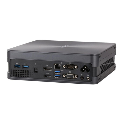
Asus V6 Series User manual

English
V6-Series
V7-Series
ASUS PC (Desktop Barebone)
Installation manual
R
a4967_V7-P5G43M_qsg.indb 1 9/4/09 3:23:37 PM

2Installation manual
English
Front panel features
1. 5.25-inch drive bay cover
2. 3.5-inch drive bay cover
3. Microphone port
4. Headphone portHeadphone port
5. USB 2.0 ports**
6. Power button
NOTE:
* The portable hard disk drive and the Infrared function are optional.
**Some models may have two additional USB 2.0 ports and/or one IEEE 1394a port, and/orSome models may have two additional USB 2.0 ports and/or one IEEE 1394a port, and/or
multiple card slot.
R
1
V6 Series Front Panel
1. Push button
2. Push button
3. Front panel coverFront panel cover
4. Power button
5. CF/MemoryStick®/,Memory Stick Pro™ card slot Secure Digital™/Multimedia Card slot™ card slot Secure Digital™/Multimedia Card slotcard slot Secure Digital™/Multimedia Card slot
/ USB 2.0 ports / Microphone port / Headphone port
R
R
V7 Series Front Panel
2
345
6
1
2
3
44
5
a4967_V7-P5G43M_qsg.indb 2 9/4/09 3:23:40 PM

3
Installation manual
English
Rear panel features
NOTE: The rear panel ports and their locations may
vary, depending on the model of your system. For
detailed descriptions, refer to the system User Guide.
1. PS/2 keyboard port ( )
2. PS/2 mouse port ( )
3. VGA port ( )
4. USB 2.0 ports ( )
(some models may have
four rear USB 2.0 ports)
5. One of the following ports:
• Optical S/PDIF Out port ( )
• Coaxial S/PDIF Out port ( )
6. IEEE 1394a port ( )
(some models only)
7. LAN (RJ-45) port ( )
8. One of the following ports:
• E-SATA port ( )
• Serial (COM1) port ( )
• DVI port ( )
• HDMI port ( )
• 6-channel • 8-channel
Internal components
1. Front panel cover
2. 5.25-inch optical drive bays
3. 2.5-inch portable hard disk drive bay
(optional)
4. Hard disk drive bay
5. Power supply unit
6. Chassis fan slot
7. ASUS motherboard*
8. Expansion slot metal brackets
9. 3.5-inch hard disk drive holder
(optional)
NOTE: *Refer to the system User Guide for
motherboard details.
1
12
3
8
9
2
3
4
9
5
7
6
8
a4967_V7-P5G43M_qsg.indb 3 9/4/09 3:23:51 PM

4Installation manual
English
Selecting the voltage
selector switch located beside the power connector. Use
this switch to select the appropriate system input voltage
according to the voltage supply in your area.
If the voltage supply in your area is 100-127 V, set the switch
to 115 V.
If the voltage supply in your area is 200-240 V, set the switch
to 230 V.
Removing the side cover and front panel assembly
1. Remove the cover screws on the rear panel.
2. Pull the side cover toward the rear panel until its hooks disengage from the chassis tab
holes. Set the side cover aside.
3. Locate the front panel assembly hooks, then lift them until they disengage from the
chassis.
4. Swing the front panel assembly to the right, until the hinge-like tabs on the right side of
the assembly are exposed.
5. Remove the front panel assembly, then set aside.
Chassis tab holes
NOTE: Refer to the system User Guide for the exact location of the voltage selector.
Installing a CPU
CAUTION! To prevent damage to the
socket pins, do not remove the PnP cap
unless you are installing a CPU.
Installing an Intel CPU
1. Locate the CPU socket on the motherboard.
2. Press the load lever with your thumb (2A),
then move it to the left (2B) until it is released
from the retention tab.
Load lever
Retention tab
2A
2B
1
2
1
2
3
3
3
4
4
4
4
a4967_V7-P5G43M_qsg.indb 4 9/4/09 3:23:54 PM

5
Installation manual
English
3. Lift the load lever in the direction of the arrow to a 135º angle.
PnP cap from the load plate window to remove (4B).
5. Position the CPU over the socket, making sure that the gold triangle is on the
bottom-left corner of the socket. Fit the socket alignment key into the CPU notch.
6. Close the load plate (6A), then push the load lever (6B) until it snaps into the retention
tab.
3
Load plate
PnP cap
4B 4A
6B
6A
Gold
triangle
mark
Alignment key
5
Installing an AMD CPU
1. Locate the CPU socket, then lift the socket lever to a 90º angle.
2. Install the CPU to the socket, making sure that the CPU corner with the gold triangle
matches the socket corner with a small triangle.
3. Push down the socket lever to secure the CPU.
CAUTION: Incorrect installation of the CPU into the socket may bend the pins and severely
damage the CPU!
1 2 3
Installing the CPU fan and heatsink assembly
Installing an Intel CPU heatsink and fan
1. Place the heatsink on top of the installed CPU,
making sure that the four fasteners match the holes
on the motherboard.
2. Push down two fasteners at a time in a diagonal
sequence to secure the heatsink and fan assembly in
place.
3. When the fan and heatsink assembly is in place,
connect the CPU fan cable to the connector on the
motherboard.
A
B
B
A
1
1
a4967_V7-P5G43M_qsg.indb 5 9/4/09 3:23:58 PM

6Installation manual
English
Installing an AMD CPU heatsink and fan
1. Place the heatsink on top of the installed CPU.
IMPORTANT.
module base; otherwise you can not lock the retention bracket.
2. Attach one end of the retention bracket to the retention module base.
3. Attach the other end of the retention bracket (near the retention bracket lock) to the
retention module base until it clicks in place.
NOTE. Your boxed CPU should come with installation instructions for the CPU, fan/heatsink assembly,
and the retention mechanism. If the instructions in this section do not match the CPU documentation,
follow the latter.
4. Push down the retention bracket lock on the retention mechanism to secure the fan
and heatsink to the module retention module base.
5. Connect the CPU fan cable to the connector on the motherboard.
CAUTION. Do not forget to connect the CPU fan connector! Hardware monitoring error can occur if
you fail to plug this connector.
Retention module base
CPU heatsink
CPU fan
Retention
bracket lock
Retention bracket
CPU fan
connector
2
1
5
3
4
Installing a DIMM
1. Locate the DIMM sockets in the motherboard.
2. Unlock a DIMM socket by pressing the retaining clips
outward.
3. Align a DIMM on the socket such that the notch on the
DIMM matches the break on the socket.
4. Push the DIMM to the socket until the retaining clips
snap inward.
CAUTION:
• Unplug the power supply before adding or removing
DIMMs. Failure to do so may cause damage to the
motherboard and/or components.
in only one direction. Do not force a DIMM into a socket
to avoid damaging the DIMM.
2
2
3
4
a4967_V7-P5G43M_qsg.indb 6 9/4/09 3:24:01 PM

7
Installation manual
English
Installing an expansion card
2. Remove the metal bracket lock.1. Remove the metal cover opposite the
slot that you intend to use.
3. Insert the card connector to the slot,
place.
4. Replace the metal bracket lock.
1
2
3
4
Installing storage drives
Optical drive
1. Place the chassis upright, then remove the upper 5.25” drive bay metal plate cover.
2. Insert the optical drive to the bay, then carefully push the drive until its screw holes
align with the holes on the bay.
3. Secure the optical drive with two screws on both sides of the bay.
4. Connect the IDE (4A) and power (4B) plugs to connectors at the back of the drive.
Floppy disk drive
If th
drive into the 3.5-inch drive bay.
1. Place the chassis upright, then remove the upper 3.5” drive bay metal plate cover.
align with the holes on the bay.
4. Connect the signal (4A) and power (4B) plugs to connectors at the back of the drive.
2
4B
4A
3
3
2
3
3
4A
4B
a4967_V7-P5G43M_qsg.indb 7 9/4/09 3:24:05 PM

8Installation manual
English
Hard disk drive
1. Remove the 3.5-inch hard drive holder out
of the chassis.
NOTE: The 3.5-inch hard drive holder is
optional.
2. Insert the hard disk drive to the 3.5-inch
hard drive holder, then carefully push the
drive until its screw holes align with the
holes on the holder.
3. Secure the hard disk drive with two screws on both sides of the bay.
4. Replace the hard drive holder to the chassis and secure the screws.
2
3
3
5. For SATA HDD: Connect the SATA
signal and power plugs to the
connectors at the back of the drive.
For IDE HDD: Connect the IDE signal and
power plugs to the connectors at the back of
the drive.
Reinstalling the front panel assembly and side cover
To reinstall the front panel assembly and side cover:
1. Insert the front panel assembly hinge-like tabs to the holes on the right side of the
chassis.
2. Swing the front panel assembly to the left, then insert the hooks to the chassis until the
3. Insert the six side cover hooks into the chassis tab holes .
5. Secure the cover with two screws you removed earlier.
SATA IDE
5
5
3
4
1
21
1
2
2
2
Chassis tab holes
5
a4967_V7-P5G43M_qsg.indb 8 9/4/09 3:24:09 PM

Français
V6-Série
V7-Série
ASUS PC (Système barebone)
Manuel d’installation
R
a4967_V7-P5G43M_qsg.indb 9 9/4/09 3:24:13 PM

10
Français
Caractéristiques de la façade
1. Cache pour baies 5.25”
2. Cache pour baies 3.5”
3. Port microphone
4. Port casque
5. Ports USB 2.0**
6.
NOTE:
* Le lecteur de disque dur portable et le capteur infrarouge sont optionnels.
** Certains modèles peuvent embarquer deux ports USB 2.0 additionnels et/ou un port IEEE
1394a et/ou plusieurs slots pour carte mémoire.
R
1
Façade de la série V6
1. Bouton-poussoir
2. Bouton-poussoir
3. Cache rétractable
5. Slot pour carte mémoire CF/MemoryStick®/Memory Stick ProTM / Slot pour carte
mémoire Secure Digital / Multimedia Card / Ports USB 2.0 / Port microphone / Prise
casque
R
R
Façade de la série V7
2
345
6
1
2
3
44
5
a4967_V7-P5G43M_qsg.indb 10 9/4/09 3:24:14 PM

11
Français
Caractéristiques de l’arrière
NOTE: Les ports du panneau arrière ainsi que leur
emplacement peuvent varier selon votre système. Pour
une description détaillée, reportez-vous au manuel de
1. Port clavier PS/2 ( )
2. Port souris PS/2 ( )
3. Port VGA ( )
4. Ports USB 2.0 ( )
(certains modèles peuvent
intégrer quatre ports USB 2.0)
5. Un des ports suivants:
• Port S/PDIF Out optique ( )
• Port S/PDIF Out coaxial ( )
6. Port IEEE 1394a ( )
(uniquement sur
certains modèles)
7. Port LAN (RJ-45) ( )
8. Un des ports suivants:
• Port E-SATA ( )
• Port Série (COM1) ( )
• Port DVI ( )
• Port HDMI ( )
• 6 canaux • 8 canaux
plus de détails.
12
3
8
9
Composants internes 1. Façade
2. Baie 5.25 pouces vide
3. Baie pour lecteur de disque dur
portable de 2.5” (optionnel)
4. Baie pour disque dur
5. Alimentation
6. Slot pour ventilateur châssis
7. Carte mère ASUS*
8. Protections métalliques pour slots
9. Cage pour disque dur de 3.5”
(optionnel)
NOTE: *Reportez-vous au manuel de
sur la carte mère.
1
2
3
4
9
5
7
6
8
a4967_V7-P5G43M_qsg.indb 11 9/4/09 3:24:24 PM

12
Français
Selecting the voltage
en fonction des standards utilisés dans votre région.
Si la tension dans votre région est de 100-127 V, passez
Si la tension dans votre région est de 200-240 V, passez
Retirer le panneau latéral et la façade
1. Retirez les vis du panneau arrière.
détachent des onglets du châssis. Mettez le panneau latéral de côté.
châssis.
du panneau soient visibles.
5. Retirez la façade, puis mettez-la de côté.
NOTE:
sélecteur de voltage.
Installer le CPU
ATTENTION:
les broches du socket, ne retirez pas le
cache PnP sauf pour installer le CPU.
Installer un processeur Intel®Pentium®4 au format LGA775
1. Localisez le socket du CPU sur la carte mère.
2. Pressez le levier avec votre pouce (2A) et
soit libéré du loquet de rétention.
Levier
Loquet de rétention
2A
2B
1
2
1
2
3
3
3
4
4
4
4
Onglets du châssis
a4967_V7-P5G43M_qsg.indb 12 9/4/09 3:24:26 PM

13
Français
5. Placez le CPU au dessus du socket, en vous assurant que le triangle doré soit dans le
loquet de rétention.
3
Plaque
Plaque de protection
4B 4A
6B
6A
Marque
triangulaire
dorée
5
Installer le AMD CPU
2. Placez le CPU sur le socket, en vous assurant que le triangle doré sur le CPU est
installé sur le triangle du socket.
ATTENTION: Une mauvaise installation du CPU sur le socket peut plier les broches et
sérieusement endommager le CPU!
1 2 3
Installer l’ensemble dissipateur-ventilateur
Installer un ensemble dissipateur-ventilateur
pour processeur Intel®Pentium®4
1. Placez le dissipateur sur le processeur, en vous
assurant que les quatres systèmes de serrage
correspondent aux trous de la carte mère.
dissipateur-ventilateur.
place, connectez le câble du ventilateur CPU au
connecteur de la carte mère étiqueté CPU_FAN.
A
B
B
A
1
1
a4967_V7-P5G43M_qsg.indb 13 9/4/09 3:24:29 PM

14
Français
Base du module de
rétention
Dissipateur CPU
Ventilateur
CPU
Clip de la patte
Connecteur
du ventilateur
CPU
2
1
5
3
4
Installer un module DIMM
1. Localisez les sockets DIMM de la carte mère.
2. Déverrouillez un socket DIMM en pressant sur les clips
3. Alignez un module DIMM sur le socket de sorte que
socket.
que les clips de rétention se referment.
ATTENTION:
ou de retirer des modules DIMMs. Ne pas le faire peut
endommager la carte mère et/ou les composants.
• Un module DDR2/DDR3 DIMM est verrouillé par une
que dans un seul sens. NE FORCEZ pas sur un
module pour le faire entrer dans son socket pour ne pas
2
2
3
4
Installer un ensemble dissipateur-ventilateur pour processeur AMD
IMPORTANT.
NOTE.
dissipateur-ventilateur, et du module de rétention. Si les instructions de cette section ne
5. Connectez le câble du ventilateur CPU au connecteur de la carte mère.
ATTENTION:
Des erreurs lors de la surveillance du matériel peuvent survenir si vous ne branchez pas ce
connecteur.
a4967_V7-P5G43M_qsg.indb 14 9/4/09 3:24:30 PM

15
Français
Installer une carte d’extension
2. Retirez le verrou des protections
métalliques.
1. Enlevez la protection métallique du
slot que vous voulez utiliser.
3. Insérez le connecteur de la carte dans
carte soit en place.
4. Replacez le verrou des protections
métalliques.
1
2
3
4
Installer des disques de stockage
Installer un lecteur optique
1. Mettez le châssis en position verticale, puis retirez le premier cache métallique pour baie
5.25”.
du lecteur.
Installer un lecteur de disquettes
lecteur de disquettes dans la baie de 3.5”.
1. Mettez le châssis en position verticale, puis retirez le premier cache métallique pour baie
3.5”.
que les pas de vis salignent avec ceux situés sur la baie.
4. Connectez le câble du lecteur de disquettes (4A) et darrière du
lecteur.
2
4B
4A
3
3
2
3
3
4A
4B
a4967_V7-P5G43M_qsg.indb 15 9/4/09 3:24:34 PM

16
Français
Installer un disque dur
1. Retirez la cage pour disque dur de 3.5” du
châssis.
NOTE: La cage pour lecteur de disque dur de
3.5” est un élément optionnel.
2. Insérez le disque dur dans la baie, puis
pas de vis salignent avec ceux situés sur
la baie.
vis.
5. Pour un disque dur SATA: connectez
les câbles SATA et dalimentation aux
arrière du disque.
Pour un disque dur IDE: connectez
les câbles IDE et dalimentation aux
arrière du disque.
Réinstaller le panneau avant/latéral
Pour replacer la façade et le panneau latéral:
1. Insérez les clapets de la façade dans les ouvertures situées sur le côté droit du
châssis.
que la façade tienne bien en place.
3. Insérez les crochets du panneau latéral dans les ouvertures situées en haut et en bas
du châssis.
5. Sécurisez le capot avec les deux vis, retirées précédemment.
IDE
2
3
3
SATA IDE
5
5
5
3
4
1
21
1
2
2
2
Onglets du châssis
a4967_V7-P5G43M_qsg.indb 16 9/4/09 3:24:36 PM

日本語
V6-シリーズ
V7-シリーズ
ASUS PC (デスクトップ ベアボーン)
インストールマニュアル
R
a4967_V7-P5G43M_qsg.indb 17 9/4/09 3:24:40 PM

18 インストールマニュアル
日本語
フロントパネルの機能
1. 5.25インチドライブベイカバー
2. 3.5インチドライブベイカバー
3. マイクポート
4. ヘッドフォンポート
5. USB2.0ポート**
6. 電源ボタン
注:
*ポータブルハードディスクドライブと赤外線機能はオプションです。
**モデルによっては、追加のUSB2.0ポートが2個、IEEE1394aポートが1個、または複数のカードスロ
ットがついてる場合があります。
R
1
V6 Series フロントパネル
1. プッシュボタン
2. プッシュボタン
3. フロントパネルカバー
4. 電源ボタン
5. CF/MemoryStick®/MemoryStickProカードスロット/SecureDigital/Multimediaカード
スロット/USB2.0ポート/マイクポート/ヘッドホンポート
R
R
V7 Series フロントパネル
2
345
6
1
2
3
44
5
a4967_V7-P5G43M_qsg.indb 18 9/4/09 3:24:43 PM

19
インストールマニュアル
日本語
背面パネル機能
注:リアパネルの各ポートと位置はシステムのモデルに
より異なります。詳細はシステムのユーザーガイドをご
覧ください。
1. PS/2キーボードポート( )
2. PS/2マウスポート( )
3. VGAポート( )
4. USB2.0ポート( )
(リアUSB2.0ポートが4基搭
載されているモデルもあります。)
5. 下のポートのいずれか1つ:
• 光学S/PDIF出力ポート( )
• 同軸S/PDIF出力ポート( )
6. IEEE1394aポート( )
(特定モデルのみ)
7. LAN(RJ-45)ポート( )
8. 下のポートのいずれか1つ:
• E-SATAポート( )
• シリアル(COM1)ポート( )
• DVIポート( )
• HDMIポート( )
9. 各オーディオポート構成:
• 6チャンネル •8チャンネル
詳細はユーザーガイドの構成表をご覧ください。
12
3
8
9
内部コンポーネント
1. フロントパネルカバー
2. 5.25インチ光学ドライブベイ
3. 2.5インチポータブルハードディスクドラ
イブベイ(オプション)
4. HDDベイ
5. 電源
6. ケースファンスロット
7. ASUSマザーボード*
8. 拡張スロットメタルブラケット
9. 3.5インチハードディスクドライブホ
ルダー(オプション)
注: *マザーボードの詳細はシステムのユーザーガイドをご覧ください。
1
2
3
4
9
5
7
6
8
a4967_V7-P5G43M_qsg.indb 19 9/4/09 3:24:54 PM

20 インストールマニュアル
日本語
電圧の選択
システムの電源には、電源コネクタの側に115V/230V
電圧セレクタスイッチがあります。このスイッチを使って、
ご利用地域の電圧に合わせて適切なシステム入力電圧
を選択します。
ご利用地域の電圧が100〜127Vの場合、スイッチを
115Vに設定します。
また、200〜240Vの場合は、スイッチを230Vに設定します。
サイドカバーとフロントパネルを取り外す
1. リアパネルのネジを外します。
2. サイドカバーをリアパネルの方向へフックがケースタブから外れるまで引きます。
3. フロントパネルのフック上げ、ケースから外します。
4. フロントパネルを、右側にあるヒンジ状のタブが露出するまで右へ移動させます。
5. フロントパネルを外します。
ケースタブホール
注:電圧セレクタの正確な位置はシステムのユーザーガイドをご覧ください。
1
2
1
2
3
3
3
4
4
4
4
警告:ソケットピンの損傷防止のため、ソ
ケットキャップはCPUを取り付けるまで外
さないでください。
CPUを取り付ける
Intel® Pentium® 4 CPU を取り付ける(LGA775 パッケージ)
1. CPUソケットの位置を確認します。
2. 親指(2A)でロードレバーを押し、保持タブか
ら外れるまで左(2B)に移動します。
ロードレバー
保持タブ
2A
2B
a4967_V7-P5G43M_qsg.indb 20 9/4/09 3:24:56 PM
Other manuals for V6 Series
3
This manual suits for next models
1
Table of contents
Languages:
Other Asus Desktop manuals

Asus
Asus P2-M3A3200 User manual

Asus
Asus AAEON BOXER-8250AI User manual

Asus
Asus Essentio CM6331 User manual

Asus
Asus CM1735 User manual

Asus
Asus AAEON RTC-710AP User manual

Asus
Asus PN Series User manual

Asus
Asus BP6320 User manual

Asus
Asus PB61V User manual

Asus
Asus BT1AD User manual

Asus
Asus VivoMini VM65N User manual