Asus C202SA Installation instructions

ASUS Computer International
C202SA: Disassembly Guide
PN: 90NX00Y2-M00040
PN: 90NX00Y2-M00050
IMPORTANT NOTICE: This document is intended for ASUS Authorized
Service Providers only. Performing any repairs without authorization
will void warranty. ASUS will not be liable for any damages that may
occur while performing any procedures provided in this guide.

C202SA Disassembly Guide
ASUS Computer International
1 of 22
Table of contents
Product Overview ..................................................................................................................................................2
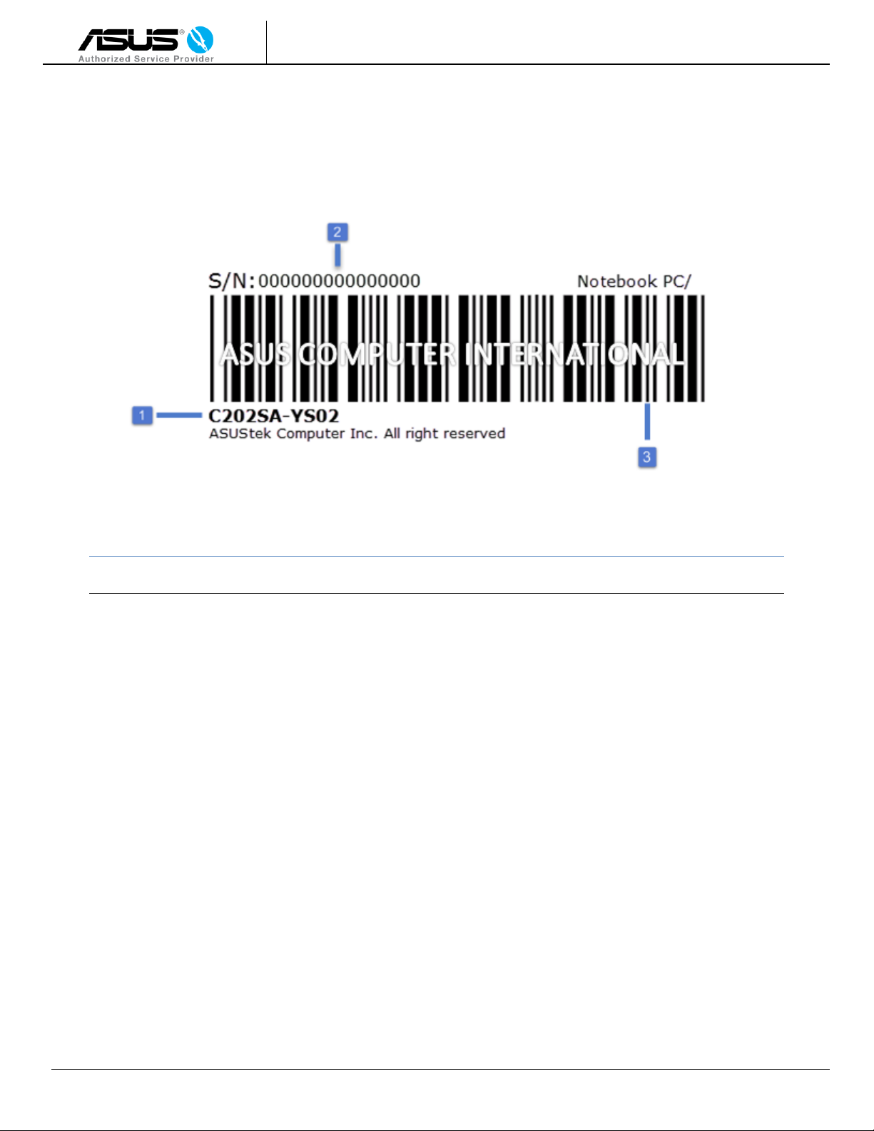
Identifying Serial Number ......................................................................................................................................5
Best Practices .........................................................................................................................................................6
Bottom Case Module (Keyboard)…………….…………….……………………….….….………………..…..…………..…………..............7
Touchpad Module……..………………………………………………………………………………….…………………………………..……..…….10
IO FFC Connector & Thermal Module………………………………………………………………………..……………………………..….…11
Battery………………………………………………………………………………………………………………………………………….……...…….….12
Daughterboard………………………………………………………………………………………………………….…………………...………………13
Motherboard and Stereo Speakers …………….……………….…………..…………….………………………………………..….…..……14
Detaching Top Cover from Bottom Chassis….……………..…………………………….……………….….……………..….….………..18
Camera Module / EDP Cable ……..………………………………………………………………………………………….….…….….…………19
Hinges …………………………..………………………………………….……………………………………..…………………….……….……….……20
Darts List Continued ……….……………………………………………………..……………………………………………………….…………....22
Disclaimer …………………………………………………………….…………………………………………………………………………….….…… 23

C202SA Disassembly Guide
ASUS Computer International
2 of 22
C202SA Overview
Front
Item
Component
Part Description
Part Number
1
LCD Panel
LCD TFT 11.6' HD US EDP
18010-11621100
2
LCD Bezel
LCD Bezel Cover
90NX00Y2-R7B010
3
Camera, MIC
HD Camera, MIC
04081-00093500
4
Touchpad
Touchpad Module
90NX00Y0-R90010
5
Keyboard
Keyboard Module
90NX00Y1-R30120
6
LCD Bezel Mylar
LCD Bezel Screw Mylar
13NX00Y2L02011

C202SA Disassembly Guide
ASUS Computer International
3 of 22
Left Side
Item
Component
Part Description
Part Number
6
HDMI
HDMI 1.4 Port
Items 6-9 on Motherboard
PN: 90NX00Y0-R00020 (2GB)
PN: 90NX00Y0-R00010 (4GB)
7
USB Port
USB 3.0
8
Headphone Jack
Single 3.5mm Jack
9
Card Reader
SD Card Reader

C202SA Disassembly Guide
ASUS Computer International
4 of 22
Right Side
Item
Component
Part Description
Part Number
7
USB Port
USB 3.0
Items 7-10
on Daughterboard
PN: 90NX00Y0-R10010
8
AC Adapter Input
100~240V AC, 50/60Hz
9
LED Indicators
Single 3.5mm Jack
10
Kensington Lock
Security Lock

C202SA Disassembly Guide
ASUS Computer International
5 of 22
Identifying Serial Number
Item
Component
1
Model
2
Serial Number
3
Barcode

C202SA Disassembly Guide
ASUS Computer International
6 of 22
Best Practices
Grounding Best Practices
Electronic components are sensitive to electrostatic discharge (ESD). Please use precaution and wear
protective gear and gloves when handling electronic components.
A discharge of static electricity from a finger or other conductor can destroy static-sensitive devices or micro-
circuitry. To prevent this from occurring, it is recommended to wear gloves and wrist strap with a grounded
surface. An electronic device exposed to ESD may not be affected at all and can work perfectly throughout a
normal cycle but may degrade during the life-cycle of the device.
Workstation
It is recommended that you work in a well-lit, static free area.
Before You Begin
Before beginning the disassembly process, please follow the preliminary steps below:
a. Power off the C202SA.
b. Disconnect the AC adapter from the device by unplugging the power cord.
c. Disconnect any external devices (ex: flash-drive, USB mouse, headphones).
Please use industry standard tools intended for PC repair purposes.
Suggested tools:
Pry Tool
Philips Screw Driver
Precision Tweezers

C202SA Disassembly Guide
ASUS Computer International
7 of 22
Bottom Case Module
1. Close the C202SA and turn it upside down with the front toward you.
2. Using a Philips screwdriver, remove the (8) screws circled in red.
3. On the top rubberized grip closest to the hinge, use the tweezers to pull out the rubber plugs on
each side to remove the remaining (2) screws underneath circled in blue.

C202SA Disassembly Guide
ASUS Computer International
8 of 22
Bottom Case Module (Keyboard)
1. Turn over the device right side up and open it with the front toward you.
2. Using the Pry Tool, insert the tool between the keyboard module and rubber chassis as shown below. Pry along
the edges of the whole keyboard until the module is separated from the rubber chassis.

C202SA Disassembly Guide
ASUS Computer International
9 of 22
3. Carefully lift the keyboard module from the top towards you as shown below.
4. Disconnect the keyboard and Touchpad FFC cable attached to the motherboard by lifting the black latch to
unlock.
You can now successfully remove the keyboard module from the chassis.
Note: The touchpad ribbon ends are marked with MB and TP. MB=Motherboard TP= Touchpad. When
reinstalling the ribbon cable, make sure the ends are connecting to the right component.

C202SA Disassembly Guide
ASUS Computer International
10 of 22
Touchpad Module
1. Turn over the Keyboard Module upside down. Use the tweezers to carefully lift the gold mylar tape
outlined in blue and remove the (3) screws circled in red.
2. Lift the touchpad module up to remove it from the keyboard module.
Touchpad Module
Keyboard Module
Note: The Gold Mylar Tape will be reused for installation.

C202SA Disassembly Guide
ASUS Computer International
11 of 22
IO FFC Cable & Thermal Module
1. Using the tweezers, carefully lift the yellow Mylar-tape outlined in red.
Note: The Yellow Mylar Tape will be reused for installation.
2. Unlock the latch by lifting the black tab up on both sides to disconnect the IO FFC Cable
3. To remove the thermal module, remove the (3) screws circled in red and blue.

C202SA Disassembly Guide
ASUS Computer International
12 of 22
Battery
1. Using a Philips screwdriver remove the (6) screws circled in red.
2. Unplug the battery connecter outlined in blue. Pull towards the right to unplug.
3. The battery is now ready for removal. You can use the pry tool to lift the battery from the chassis.

C202SA Disassembly Guide
ASUS Computer International
13 of 22
Daughterboard
1. The Daughterboard is outlined in blue. Use the Philips screwdriver to remove the (2) screws circled in red.
2. Carefully lift the Daughterboard up and pull towards the left to remove it.

C202SA Disassembly Guide
ASUS Computer International
14 of 22
Motherboard & Stereo Speakers
4. Once the motherboard has been removed, you can now disconnect and remove the stereo speakers.
1. Use the Philips screwdriver to remove the (4)screws circled in red and (1) circled in blue.
2. Remove (1) screw securing the WLAN module on the motherboard circled in yellow. Disconnect the WLAN card
outlined in also yellow.
3. Carefully lift up the mylar-tape using the tweezers to detach ribbon cable from motherboard outlined in purple.
There will be (1) remaining screw to remove underneath the mylar-tape. You will now be able to remove the
motherboard.
Note: The mylar tape will be reused for installation.

C202SA Disassembly Guide
ASUS Computer International
15 of 22
LCD Bezel
1. Lay the C202SA flat at 180° degrees as shown below.
2. Use the pry tool to carefully remove the LCD screw mylar covering the screws on both the left and
right side of the bezel. Pry in a circular motion as shown below.
3. Use a Philips screwdriver to remove the (2) screws circled in red.

C202SA Disassembly Guide
ASUS Computer International
16 of 22
4. Insert the pry tool in between the Bezel and LCD panel as shown below. Every ½ inch has a pry point; pry along the
edges of the LCD Bezel until fully detached from LCD Panel.
5. Use the Philips screwdriver to remove the (4) screws circled in red.

C202SA Disassembly Guide
ASUS Computer International
17 of 22
6. Carefully lift the LCD panel until the back is visible. Use the tweezers to lift the clear mylar-tape and unplug the EDP
cable on the bottom of the panel.
7. You can now remove the LCD Panel from the top cover assembly.
Note: The mylar tape will be reused for installation.

C202SA Disassembly Guide
ASUS Computer International
18 of 22
Detaching Top Cover from Bottom Chassis
2. Lift the hinges up to detach the top module from bottom chassis.
1. Remove the (4) screws circled in red on both sides of the hinges.

C202SA Disassembly Guide
ASUS Computer International
19 of 22
Camera Module/ EDP Cable
1. Disconnect the camera cable from the camera Module.
2. On the bottom of the top cover assembly, use the tweezers to carefully lift the black mylar-tape that is securing
the LCD cable.
3. You can now remove the camera module and EDP cable from the top cover assembly.
Note: The mylar tape will be reused for installation.
Other manuals for C202SA
1
Table of contents
Other Asus Laptop manuals

Asus
Asus X102B Guide

Asus
Asus N56VM User manual

Asus
Asus F8VA Instructions for use

Asus
Asus G74S Series Installation instructions

Asus
Asus S7F User manual

Asus
Asus Zephyrus GX531GW-ES008R User manual

Asus
Asus W1V Instructions for use

Asus
Asus A46CB User manual

Asus
Asus Eee PC 701SD XP User manual

Asus
Asus Eee PC 900HD Series Operating manual