Asus FX505DY Series User manual

Disassembly Procedure
V1.0
2 - 1
Rev.
Change History
Change Time
Originator
V1.0
First Release
2019/1/17
Susan_Tsai
V2.0
Add MB ABSORBER/FX505DY RX560 GPU ABSORBER
2019/1/18
Susan_Tsai
V2.1
P11: Add SSD ABSORBER/SSD AL FOIL.
P15: Add MB TOP CU FOIL.
P22: Add MB TOP ABSORBER/MB TOP SSD ABSORBER.
P23: Add MB Thermal KAPTON/MB GPU KAPTON.
P26: Add KB TOP CU WASHER.
2019/1/17
Stephanie
V2.2
P12: Add FX505DY WLAN INDICATOR
2019/4/16
Stephanie
Disassembly Procedure
Please follow the information provided in this section to perform the complete disassembly procedure of the
Notebook. Be sure to use proper tools described before.
SUS FX505DY series notebook consists of various modules. This chapter describes the procedure for the
complete notebook disassembly and assembly (Assemble document please look up from the last page).
In addition, in between procedures, the detailed disassembly procedure of individual modules will be
provided for your service needs.
The disassembly procedure consists of the following steps:
Service overview
Appropriate Tools
Bottom case Module
Battery Module
HDD
SSD
WLAN Module
Memory Module
Thermal and Fan Module
Main Board
LED Board
Topcase Module
LCD Module
Gap Step
A

Disassembly Procedure
V1.0
2 - 2
Service Overview
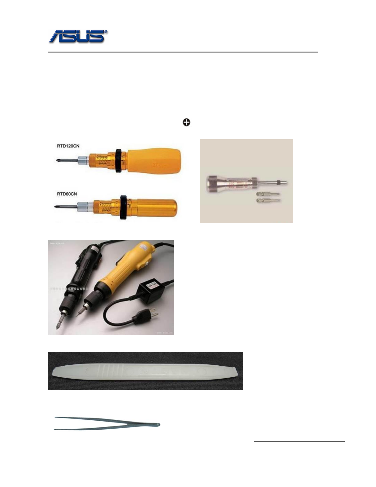
Please pay special attention to the cautions below to prevent any damages to the notebook and also please be
sure to select the appropriate tools described in this section to perform any services desired.
Precautions
Before you perform any service and or repair on the notebook, please follow the steps below first.
1. Be sure that the notebook is powered down.
2. Disconnect the AC plug from the notebook.
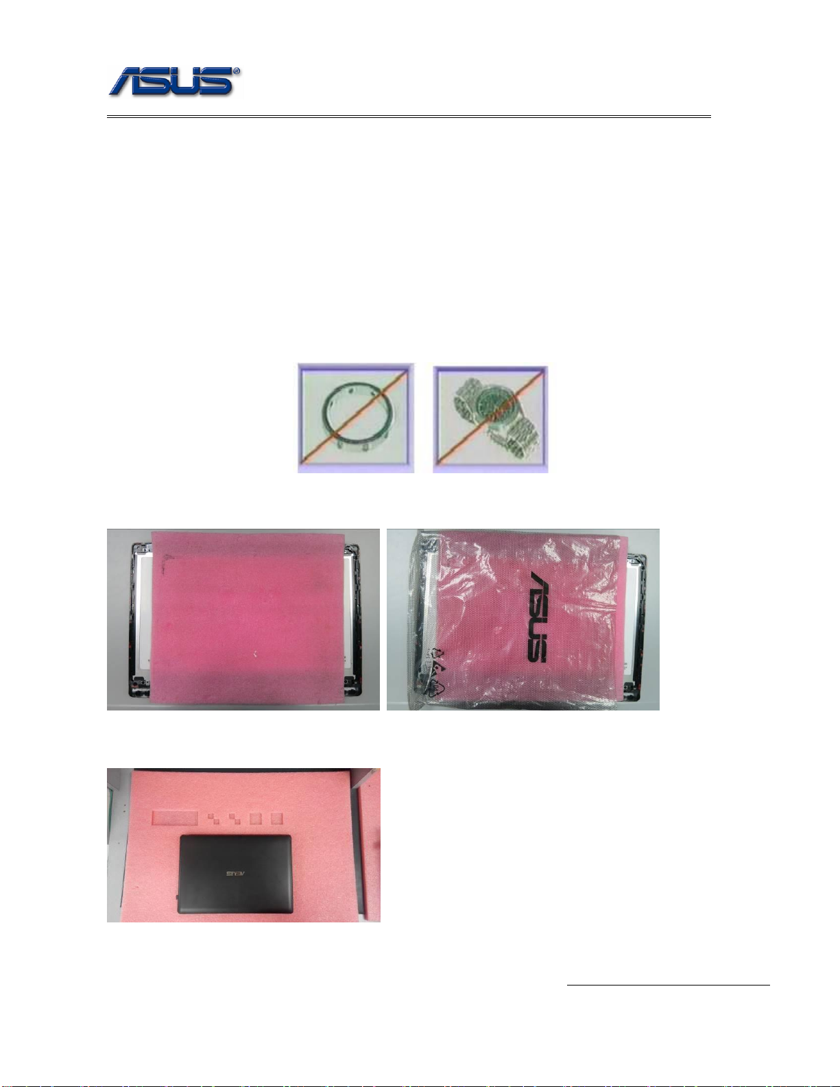
3. Remove all rings, watches and any other metal objects from your hands.
4. Always wear a ground strap on your hand to protect the notebook from static discharge.
5. Please refer to “ANSI ESD S20.20”about ESD protection measure.
6. Put disassemble the parts in the functional PE BAG for avoid any damages of the A/B/C/D part.
7. Environment temperature is 20-30 ℃and humidity is 40% - 70%.
8. Avoid scratching the surface of the machine, please use anti-static and soft materials to put on desk in
repair environment as below photo.
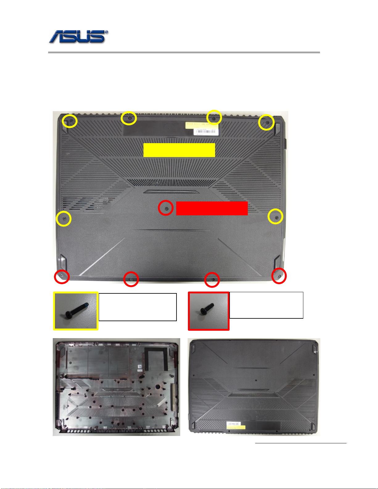
9. Screw Appearance Criteria.

Disassembly Procedure
V1.0
2 - 4
Appropriate Tools
The illustrations below show the appropriate tools that should be used for the notebook’s service and repair.
Cross Screwdriver
Please according to different screw specification and choose different screwdriver and head.
Below photos are for reference only.
Use a cross screwdriver to fasten/remove screws.
Plastic Blade (PN: 20LT0-0005O000)
Tweezers
Use a pair of tweezers to remove/insert flexible cables.

Disassembly Procedure
V1.0
2 - 6
Bottom case Module
The illustration below shows how to remove the bottom case module.
1. Remove 11 pcs screws on the bottom case.
Assembly Notice: Follow the reverse numbers to lock screws.
Screw tightening torque (Kg F-cm): 3kgf-cm
13050-B2813000 *6
13GMBKXD061Z-1 *5
13050-B2813000 :
SCREW M2.5*13L
(4.5,0.8) (K) B-ZN NY #1
13GMBKXD061Z-1:
SCREW M2.5*6L
(4.6,0.85) (K) B-ZN NY
#1

Disassembly Procedure
V1.0
2 - 8
Battery Module
The illustration below shows how to remove the battery module.
1. Disconnect the connector at PCB end.
2. Remove 1 screws on battery module.
Assembly Notice: Follow the reverse numbers to lock screws.
Screw tightening torque (Kg F-cm): 3kgf-cm
Disconnect the battery cable.
Notice: Before disassembly, please be sure to pull out adapter and disconnect the battery more than ten
seconds in order to avoid IC damage. BACK
13GMBKXD061Z-1:
SCREW M2.5*6L
(4.6,0.85) (K) B-ZN NY
#1

Disassembly Procedure
V1.0
2 - 9
HDD
The illustration shows how to remove the HDD.
1. Remove 2 screws on HDD.
Assembly Notice: Follow the reverse numbers to lock screws.
Screw tightening torque (Kg F-cm): 3kgf-cm
2. Disconnect HDD.
3. Remove 3 screws on HDD Bracket.
Assembly Notice: Follow the reverse numbers to lock screws.
Screw tightening torque (Kg F-cm): 3kgf-cm
BACK
13GMBKXD061Z-1:
SCREW M2.5*6L
(4.6,0.85) (K) B-ZN NY #1
13GMAKXF030B-1:
SCREW M3*3L
(5.25,0.8) (K) B-NI

Disassembly Procedure
V1.0
2 - 10
SSD
The illustrations below show how to remove the SSD.
1. Remove a screw from SSD.
Assembly Notice: Follow the reverse numbers to lock screws.
Screw tightening torque (Kg F-cm): 2.0kgf-cm
13GMBK3C036Z-1:
SCREW M2*3L (4.6,0.8)
(K) B-ZN NY #1

Disassembly Procedure
V1.0
2 - 12
WLAN Module
The illustration below shows how to remove the WLAN module.
1. Remove mylar and disconnect antenna.
2. Remove 1pcs screw on WLAN module.
Assembly Notice: Follow the reverse numbers to lock screws.
Screw tightening torque (Kg F-cm): 2.0kgf-cm
3. Remove WLAN.
Notice: Add WLAN Indicator on WLAN card.
BACK
13GMBK3C036Z-1:
SCREW M2*3L (4.6,0.8)
(K) B-ZN NY #1
13NR01A0T01011
FX505DY WLAN
INDICATOR//上藝
Align the mental cover edge to attach
Connect White
Antenna
Connect Black
Antenna

Disassembly Procedure
V1.0
2 - 14
Thermal and Fan Module
The illustration below shows how to remove the Thermal and fan module.
1. Remove 13 screws on the thermal module and take it away.
Assembly Notice: Follow the reverse numbers to lock screws.
Screw tightening torque (Kg F-cm): 2.0kgf-cm
2. Disconnect fan cables.
13GMBK3C045W-1:
SCREW M2*4.5L
(4.5,0.8) (K) W-NI NY #1

Disassembly Procedure
V1.0
2 - 15
Notice: Add MB TOP CU FOIL.
13NR01A0M02011
FX505DY MB TOP
CU FOIL

Disassembly Procedure
V1.0
2 - 17
Main Board
The illustrations below show how to remove the main board.
1. Disconnect eDP/FFC/Touchpad FFC/Speaker cable/DC IN cable from MB.
a. Remove KB FFC.
b. Remove touchpad FFC.
c. Remove KB FFC.
a
b
d
e
f
c

Disassembly Procedure
V1.0
2 - 18
d. Disconnect EDP cable.
e. Disconnect speaker cable.
f. Disconnect DC jack cable.

Disassembly Procedure
V1.0
2 - 19
2. Remove 5 screws on MB.
Assembly Notice: Follow the reverse numbers to lock screws.
Screw tightening torque (Kg F-cm): 2.0kgf-cm
3. Remove LED FFC from MB.
13GMBK3C036Z-1: SCREW M2*
3L (4.6,0.8) (K) B-ZN NY #1

Disassembly Procedure
V1.0
2 - 20
4. Mylar on MB
BACK
13NR01A0L02011 FX505DY RX560 GPU MYLAR
13NR01A0L02021 FX505DY RX560 GPU MYLAR
13NR01A0L01011 FX505DY FP5 CPU MYLAR
13NR01A0L01021FX505DY FP5 CPU MYLAR
13NR00S0L43011 FX505GE DIMM COVER MYLAR
13NR00S0L43021 FX505GE DIMM COVER MYLAR
13NR00S0L50011FX505GE PCB MYLAR1
13NR00S0L50021 FX505GE PCB MYLAR1
13NR00S0AM0401 FX505GE GPU BKT ASSY
13NR00S0M06011 FX505GE GPU BRACKET
13NR00S0AM0301 FX505GE CPU BKT
13NR00S0M05011 FX505GE CPU BRACKET
13NR00S0L97011 FX505GE SAFETY SPONGE
13NR00S0L97021 FX505GE SAFETY SPONGE
13NR00S0L55011 FX505GE SSD MYLAR
13NR00S0L55021 FX505GE SSD MYLAR
13NR00S0L66011 FX505GE MB ABSORBER
13NR00S0L66021 FX505GE MB ABSORBER
13NR01A0L03011 FX505DY RX560 GPU ABSORBER
13NR01A0L03021 FX505DY RX560 GPU ABSORBER
Table of contents
Other Asus Laptop manuals

Asus
Asus Eee PC 701SD XP Operating manual

Asus
Asus Transformer Book Flip TP300UA Guide

Asus
Asus UL30A Instructions for use

Asus
Asus VivoBook Flip 12 TP203NA-WB01T Guide

Asus
Asus A55A User manual

Asus
Asus N45SL User manual

Asus
Asus Eee PC 1002HA XP User manual

Asus
Asus F7E Instructions for use

Asus
Asus 1001PX-EC27-BK User manual

Asus
Asus E14715 User manual