Asus G72Gx User manual

Notebook PC User Manual
September 2009
E4965

2
Notebook PC User Manual
Table of Contents
Safety Precautions ............................................................................................. 3
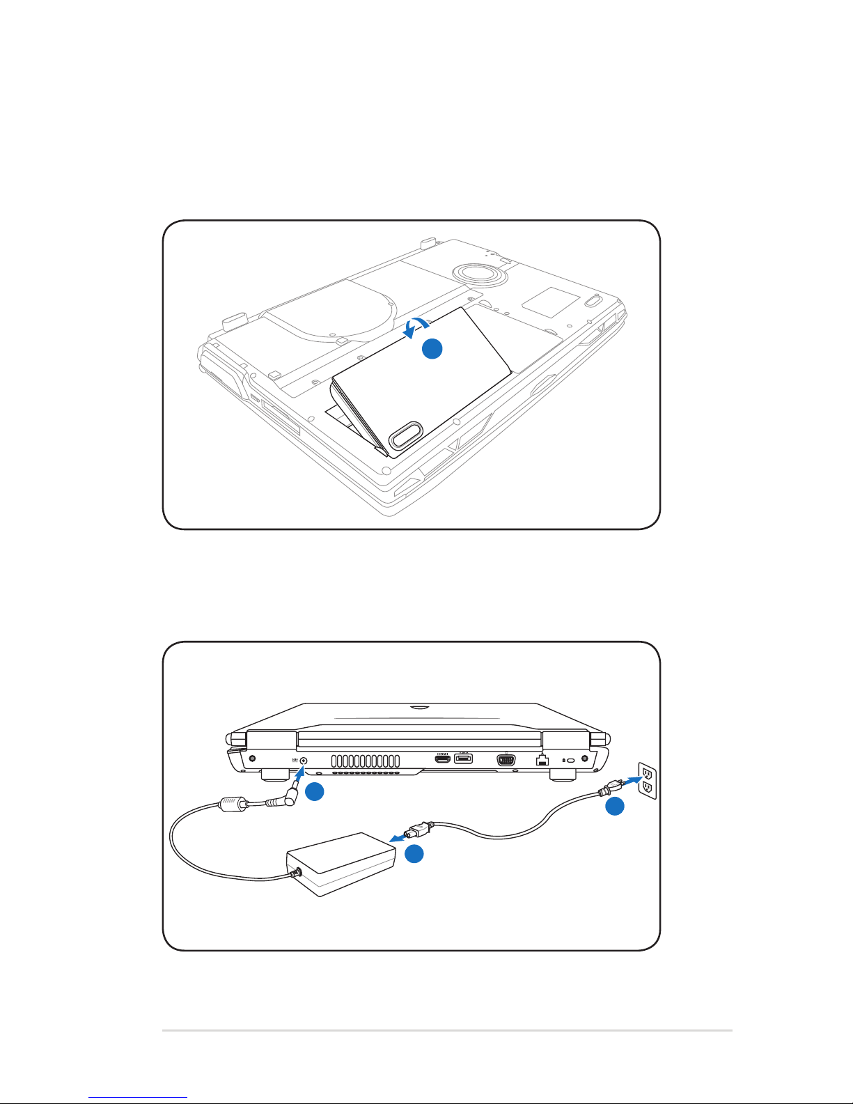
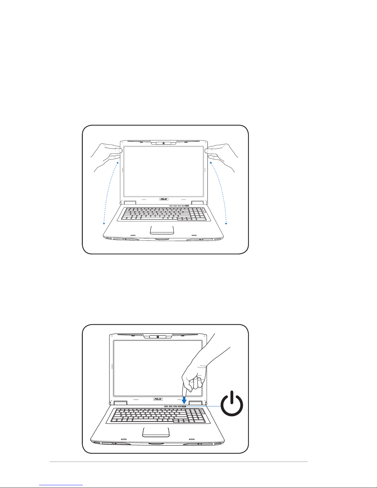
Preparing your Notebook PC......................................................................... 5
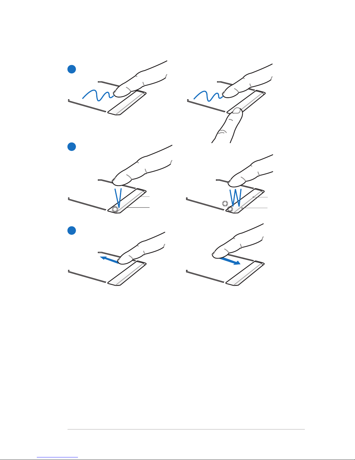
Using the Touchpad .......................................................................................... 7
Knowing the Parts.............................................................................................. 8
Right Side ............................................................................................................ 8
Left Side .............................................................................................................10
Rear Side ............................................................................................................12
Front Side ..........................................................................................................14
Recovering Your Notebook PC ....................................................................15
Using Recovery Partition ............................................................................15
Using Recovery DVD (on selected models)...........................................16
Declarations and Safety Statements .........................................................18
Federal Communications Commission Statement.............................18
FCC Radio Frequency (RF) Exposure Caution Statement.................19
Declaration of Conformity(R&TTE directive 1999/5/EC)...................19
CE Mark Warning.............................................................................................20
IC Radiation Exposure Statement for Canada ......................................20
Wireless Operation Channel for Different Domains...........................21
France Restricted Wireless Frequency Bands .......................................21
UL Safety Notices............................................................................................23
Power Safety Requirement .........................................................................24
REACH .............................................................................................................24
Nordic Lithium Cautions (for lithium-ion batteries)...........................25

Notebook PC User Manual
3
Safety Precautions
The following safety precautions will increase the life of the
Notebook PC. Follow all precautions and instructions. Except as
described in this manual, refer all servicing to qualified personnel.
Battery safety warning:
DO NOT throw the
battery in fire. DO NOT
short circuit the contacts.
DO NOT disassemble the
battery.
DO NOT leave the
Notebook PC on your lap
or any part of the body
to prevent discomfort
or injury from heat
exposure.
DO NOT expose to dirty
or dusty environments.
DO NOT operate during a
gas leak.
DO NOT expose to
strong magnetic or
electrical fields.
DO NOT expose to or
use near liquids, rain,
or moisture. DO NOT
use the modem during
electrical storms.
DO NOT press or touch
the display panel. Do not
place together with small
items that may scratch or
enter the Notebook PC.
DO NOT place on
uneven or unstable work
surfaces. Seek servicing
if the casing has been
damaged.
DO NOT place or drop
objects on top and
do not shove any
foreign objects into the
Notebook PC.
Disconnect the AC power and remove the battery pack(s) before
cleaning.Wipe the Notebook PC using a clean cellulose sponge
or chamois cloth dampened with a solution of nonabrasive
detergent and a few drops of warm water and remove any extra
moisture with a dry cloth.

4
Notebook PC User Manual
SAFE TEMP:This
Notebook PC should
only be used in
environments with
ambient temperatures
between 10°C (50°F) and
35°C (95°F)
DO NOT carry or cover
a Notebook PC that
is powered ON with
any materials that will
reduce air circulation
such as a carrying bag.
DO NOT throw the Notebook PC in municipal waste.This
product has been designed to enable proper reuse of parts
and recycling.The symbol of the crossed out wheeled bin
indicates that the product (electrical, electronic equipment
and mercury-containing button cell battery) should not
be placed in municipal waste. Check local regulations for
disposal of electronic products.
DO NOT throw the battery in municipal waste.The symbol
of the crossed out wheeled bin indicates that the battery
should not be placed in municipal waste.
INPUT RATING: Refer to
the rating label on the
bottom of the Notebook
PC and be sure that your
power adapter complies
with the rating.
Incorrect installation
of battery may cause
explosion and damage
the Notebook PC.
DO NOT use damaged
power cords, accessories,
or other peripherals.
DO NOT use strong
solvents such as
thinners, benzene, or
other chemicals on or
near the surface.

Notebook PC User Manual
5
Preparing your Notebook PC
These are only quick instructions for using your Notebook PC.
Installing the Battery Pack
Connecting the Power Adapter
1
1
2
3

6
Notebook PC User Manual
Opening the LCD display panel
1. Press the display panel button and lift up the display panel with
your thumb.
2. Slowly tilt the display panel forward or backward to a
comfortable viewing angle.
Turning on the Power
1. Push and release the power button located beneath the LCD
display panel.
2. Use [Fn]+[F5] or [Fn]+[F6] to djust the LCD brightness.

Notebook PC User Manual
7
C
A
A. Slide your finger across the touchpad to move the pointer.You
can also hold the left button and slide your finger to drag the
selected item.
B. Use the left and right buttons like a standard mouse.
C. Slide your finger up or down on the right side to scroll up or
down a window.
Using the Touchpad
Left button
Right button
B
Left button
Right button

8
Notebook PC User Manual
Knowing the Parts
Right Side
1
2
3
ExpressCard Slot
One 26pin Express card slot is available to support one
ExpressCard/34mm expansion card.This new interface
is faster by using a serial bus supporting USB 2.0 and PCI
Express instead of the slower parallel bus used in the PC
card slot. (Not compatible with previous PCMCIA cards.)
Wireless Switch
Enables or disables the built-in wireless LAN and Bluetooth
(selected models).When enabled, the wireless status
indicator will light.Windows software settings are necessary
before use.
SPDIF Output Jack
This jack provides connection to SPDIF (Sony/Philips Digital
Interface) compliant devices for digital audio output. Use
this feature to turn the Notebook PC into a hi-fi home
entertainment system.
Headphone Output Jack
The stereo headphone jack (1/8 inch) is used to connect
the Notebook PC’s audio out signal to amplified speakers
or headphones. Using this jack automatically disables the
built-in speakers.
1 2 3 4 5 6 6
Combo

Notebook PC User Manual
9
Headphone Output Jack
The stereo headphone jack (1/8 inch) is used to connect
the Notebook PC’s audio out signal to amplified speakers
or headphones. Using this jack automatically disables the
built-in speakers.
Microphone Input Jack
The mono microphone jack (1/8 inch) can be used to
connect an external microphone or output signals from
audio devices. Using this jack automatically disables the
built-in microphone.Use this feature for video conferencing,
voice narrations, or simple audio recordings.
USB Port (2.0/1.1)
The USB (Universal Serial Bus) port is compatible with USB
2.0 or USB 1.1 devices such as keyboards, pointing devices,
cameras, hard disk drives, printers, and scanners connected
in a series up to 12Mbits/sec (USB 1.1) and 480Mbits/sec
(USB 2.0). USB allows many devices to run simultaneously
on a single computer, with some peripherals acting as
additional plug-in sites or hubs.USB supports hot-swapping
of devices so that most peripherals can be connected or
disconnected without restarting the computer.
4
5
6

10
Notebook PC User Manual
Left Side
1
2
3
Antenna Input (on selected models)
The antenna input is for TV (on selected models) frequency
signal and allows for use with the provided digital TV
antenna or input from subscription television services.
The provided antenna can receive digital TV. Cable service
connection can receive digital TV, analog TV, depending on
paid services. Note: Use the provided adapter for use with
coaxial connectors.
USB 2.0 Port
The USB (Universal Serial Bus) port is compatible with USB
2.0 or USB 1.1 devices such as keyboards, pointing devices,
cameras, hard disk drives, printers, and scanners connected
in a series up to 12Mbits/sec (USB 1.1) and 480Mbits/sec
(USB 2.0). USB allows many devices to run simultaneously
on a single computer, with some peripherals acting as
additional plug-in sites or hubs.USB supports hot-swapping
of devices so that most peripherals can be connected or
disconnected without restarting the computer.
IEEE1394 Port (on selected models)
IEEE1394 is a high speed serial bus like SCSI but has simple
connections and hot-plugging capabilities like USB.The
interface IEEE1394 has a bandwidth of 100-400 Mbits/sec
and can handle up to 63 units on the same bus. IEEE1394
is also used in high-end digital equipment and should be
marked “DV” for Digital Video port.
1 2 2 3 4 5 6 7

Notebook PC User Manual
11
5
6
Flash Memory Slot
Normally an external memory card reader must be
purchased separately in order to use memory cards from
devices such as digital cameras, MP3 players, mobile
phones, and PDAs.This Notebook PC has a built-in high-
speed memory card reader that can conveniently read from
and write to many flash memory cards.
Optical Drive
The Notebook PC comes in various models with different
optical drives.The Notebook PC’s optical drive may support
compact discs (CD) and/or digital video discs (DVD) and
may have recordable (R) or re-writable (RW) capabilities.
See the marketing specifications for details on each model.
Optical Drive Electronic Eject
The optical drive eject has an electronic eject button for
opening the tray.You can also eject the optical drive tray
through any software player or by right clicking the optical
drive in Windows“Computer”and selecting Eject.This eject
also functions as the optical drive activity indicator which
shows when data is being transferred by the optical disk
drive.This indicator will light in proportion to the data size
transferred.
Optical Drive Emergency Eject
(location varies by model)
The emergency eject is used to eject the optical drive tray
in case the electronic eject does not work. Do not use the
emergency eject in place of the electronic eject.
7
4

12
Notebook PC User Manual
Rear Side
21 3 4 5 6 7
Power (DC) Input
The supplied power adapter converts AC power to DC
power for use with this jack. Power supplied through this
jack supplies power to the Notebook PC and charges the
internal battery pack.To prevent damage to the Notebook
PC and battery pack, always use the supplied power
adapter.
1
Ensure that paper, books, clothing, cables, or other objects do not
block any of the air vents or else overheating may occur.
HDMI
HDMI Port (on selected models)
HDMI (High-Definition Multimedia Interface) is an
uncompressed all-digital audio/video interface between
any audio/video source, such as a set-top box, DVD player,
and A/V receiver and an audio and/or video monitor, such
as a digital television (DTV). Supports standard, enhanced,
or high-definition video, plus multi-channel digital audio
on a single cable. It transmits all ATSC HDTV standards and
supports 8-channel digital audio, with bandwidth to spare
to accommodate future enhancements or requirements.
2
3
The adapter may become warm to hot when in use. Ensure not
to cover the adapter and keep it away from your body.
Air Vents
The air vents allow cool air to enter and warm air to exit the
Notebook PC.

Notebook PC User Manual
13
7
E-SATA
E-SATA Port (on selected models)
External SATA or eSATA allows external connection of Serial-
ATA devices originally designed for use inside the computer.
It is up to six times faster than existing USB 2.0, & 1394 for
external storage solutions and is also hot pluggable using
shielded cables and connectors up to two meters.
Display (Monitor) Output
The 15-pin D-sub monitor port supports a standard VGA-
compatible device such as a monitor or projector to allow
viewing on a larger external display.
LAN Port
The RJ-45 LAN port with eight pins is larger than the RJ-11
modem port and supports a standard Ethernet cable for
connection to a local network.The built-in connector allows
convenient use without additional adapters.
Kensington® Lock Port
The Kensington® lock port allows the Notebook PC to
be secured using Kensington® compatible Notebook PC
security products.These security products usually include
a metal cable and lock that prevent the Notebook PC to
be removed from a fixed object. Some may also include a
motion detector to sound an alarm when moved.
6
5
4

14
Notebook PC User Manual
Front Side
1 12 3 4
Audio Speakers
The built-in stereo speaker system allows you to hear audio
without additional attachments.The multimedia sound
system features an integrated digital audio controller
that produces rich, vibrant sound (results improved with
external stereo headphones or speakers). Audio features
are software controlled.
Status Indicators (front)
Status indicators represent various hardware/software
conditions.
CIR (Consumer Infrared) Port (on selected models)
The consumer infrared (IrDA) communication port allows
convenient wireless control of the provided multimedia
software in selected models using the provided wireless
remote control in selected models.
Display Panel Button
Press the display panel button to open the display panel.
1
2
3
4
WARNING! When opening, do not force the display panel
down to the table or else the hinges may break! Never lift the
Notebook PC by the display panel!

Notebook PC User Manual
15
Recovering Your Notebook PC
Using Recovery Partition
The Recovery Partition quickly restores your Notebook PC’s software
to its original working state. Before using the Recovery Partition,
copy your data files (such as Outlook PST files) to floppy disks or to
a network drive and make note of any customized configuration
settings (such as network settings).
About the Recovery Partition
The Recovery Partition is a reserved space on your hard disk drive
used to restore the operating system, drivers, and utilities installed
on your Notebook PC at the factory.
IMPORTANT! DO NOT delete the partition named RECOVERY.
The Recovery Partition is created at the factory and cannot be
restored if deleted.Take
your Notebook PC to an
authorized ASUS service
center if you have problems
with the recovery process.
Using the Recovery Partition:
1. Press [F9] during bootup.
2. Press [Enter] to select Windows Setup [EMS Enabled].
3. Read the ASUS Preload Wizard screen and click Next.
4. Select a partition option and click Next. Partition options:
Recover Windows to first partition only.
This option deletes only the first partition and allows you to keep other
partitions,and to create a new system partition as drive“C”.
Recover Windows to entire HD.
This option deletes all partitions from your hard disk drive and creates
a new system partition as drive“C”.

16
Notebook PC User Manual
Recover Windows to entire HD with 2 partition.
This option deletes all partitions from your hard drive and creates two
new partitions“C”(60%) and“D”(40%).
5. Follow the onscreen instructions to complete the recovery
process.
Visit the ASUS website at www.asus.com for updated drivers and
utilities.
Using Recovery DVD (on selected models)
Creating the Recovery DVD:
1. Double-click the AI Recovery Burner icon on the Window
desktop.
2. Insert a blank
writable DVD
into the optical
drive and click
Start to start
creating the
Recovery DVD.
3. Follow the onscreen instructions to complete creating the
recovery DVD.
Prepare three blank writable DVDs to create the Recovery DVD.
IMPORTANT! Remove the external hard disk drive before
performing system recovery on your Notebook PC. According
to Microsoft, you may lose important data because of setting
up Windows Vista on the wrong disk drive or formatting the
incorrect drive partition. Refer to http://support.microsoft.com/
kb/937251/en-us for more details.

Notebook PC User Manual
17
Using the Recovery DVD:DVD::
1. Insert the Recovery DVD into the optical drive.Your Notebook
PC needs to be powered ON.
2. Restart the Notebook PC and press [Esc] on bootup and select
the optical drive (may be labeled as“CD/DVD”) and press [Enter]
to boot from the Recovery DVD.
3. Select a partition option and click Next. Partition options:
Recover Windows to first partition only.
This option deletes only the first partition and allows you to keep other
partitions,and to create a new system partition as drive“C”.
Recover Windows to entire HD.
This option deletes all partitions from your hard disk drive and creates
a new system partition as drive“C”.
Recover Windows to entire HD with 2 partition.
This option deletes all partitions from your hard drive and creates two
new partitions“C”(60%) and“D”(40%).
4. Follow the onscreen instructions to complete the recovery
process.
WARNING: Do not remove the Recovery disc, unless instructed to
do so, during the recovery process or else your partitions will be
unusable.
Visit the ASUS website at www.asus.com for updated drivers and
utilities.

18
Notebook PC User Manual
Declarations and Safety Statements
Federal Communications Commission Statement
This device complies with FCC Rules Part 15. Operation is subject to
the following two conditions:
• This device may not cause harmful interference.
• This device must accept any interference received, including
interference that may cause undesired operation.
This equipment has been tested and found to comply with the
limits for a class B digital device, pursuant to Part 15 of the Federal
Communications Commission (FCC) rules. These limits are designed
to provide reasonable protection against harmful interference in
a residential installation. This equipment generates, uses, and can
radiate radio frequency energy and, if not installed and used in
accordance with the instructions, may cause harmful interference
to radio communications. However, there is no guarantee that
interference will not occur in a particular installation. If this equipment
does cause harmful interference to radio or television reception,
which can be determined by turning the equipment off and on, the
user is encouraged to try to correct the interference by one or more of
the following measures:
• Reorient or relocate the receiving antenna.
• Increase the separation between the equipment and receiver.
• Connect the equipment into an outlet on a circuit different from
that to which the receiver is connected.
• Consult the dealer or an experienced radio/TV technician for
help.
The use of a shielded-type power cord is required in order to
meet FCC emission limits and to prevent interference to the
nearby radio and television reception. It is essential that only
the supplied power cord be used. Use only shielded cables to
connect I/O devices to this equipment.You are cautioned that
changes or modifications not expressly approved by the party
responsible for compliance could void your authority to operate
the equipment.

Notebook PC User Manual
19
(Reprinted from the Code of Federal Regulations #47, part 15.193, 1993.
Washington DC: Office of the Federal Register, National Archives and
Records Administration, U.S. Government Printing Office.)
FCC Radio Frequency (RF) Exposure Caution
Statement
Any changes or modifications not expressly approved by the
party responsible for compliance could void the user’s authority
to operate this equipment.“The manufacture declares that
this device is limited to Channels 1 through 11 in the 2.4GHz
frequency by specified firmware controlled in the USA.”
This equipment complies with FCC radiation exposure limits set forth
for an uncontrolled environment.To maintain compliance with FCC
RF exposure compliance requirements, please avoid direct contact
to the transmitting antenna during transmitting. End users must
follow the specific operating instructions for satisfying RF exposure
compliance.
Declaration of Conformity
(R&TTE directive 1999/5/EC)
The following items were completed and are considered relevant
and sufficient:
• Essential requirements as in [Article 3]
• Protection requirements for health and safety as in [Article 3.1a]
• Testing for electric safety according to [EN 60950]
• Protection requirements for electromagnetic compatibility in
[Article 3.1b]
• Testing for electromagnetic compatibility in [EN 301 489-1] & [EN
301 489-17]
• Effective use of the radio spectrum as in [Article 3.2]
• Radio test suites according to [EN 300 328-2]

20
Notebook PC User Manual
CE Marking
CE marking for devices without wireless LAN/Bluetooth
The shipped version of this device complies with the requirements
of the EEC directives 2004/108/EC“Electromagnetic compatibility”
and 2006/95/EC“Low voltage directive”.
CE marking for devices with wireless LAN/ Bluetooth
This equipment complies with the requirements of Directive 1999/5/
EC of the European Parliament and Commission from 9 March, 1999
governing Radio and Telecommunications Equipment and mutual
recognition of conformity.
IC Radiation Exposure Statement for Canada
This equipment complies with IC radiation exposure limits set forth
for an uncontrolled environment.To maintain compliance with IC
RF exposure compliance requirements, please avoid direct contact
to the transmitting antenna during transmitting. End users must
follow the specific operating instructions for satisfying RF exposure
compliance.
Operation is subject to the following two conditions:
• This device may not cause interference and
• This device must accept any interference, including interference
that may cause undesired operation of the device.
To prevent radio interference to the licensed service (i.e. co-channel
Mobile Satellite systems) this device is intended to be operated
indoors and away from windows to provide maximum shielding.
Equipment (or its transmit antenna) that is installed outdoors is
subject to licensing.
This manual suits for next models
1
Table of contents
Other Asus Laptop manuals