ATA AXESS 2000 Pro Series User manual

AUTOMATIC TECHNOLOGY AUSTRALIA PTY LTD
OWNERS COPY
Installation Instructions
COMMERCIAL ROLLER
SHUTTER OPENER
Pro Series 2000
WARNING
It is vital for the safety of persons to follow all
instructions. Failure to comply with the installation
instructions and the safety warnings may result in
serious personal injury and/or property and remote
control opener damage.
Please save these instructions for future reference.

Automatic Technology Australia Pty Ltd to the extent that such may be lawfully excluded hereby expressly disclaims all
conditions or warranties, statutory or otherwise which may be implied by laws as conditions or warranties of purchase of
an Automatic Technology Australia Pty Ltd automatic opener and Automatic Technology Australia Pty Ltd hereby
further expressly excludes all or any liability for any injury, damage, cost, expense or claim whatsoever suffered by any
person as a result whether directly or indirectly from failure to install the Automatic Technology Australia automatic
opener in accordance with these installation instructions.
CONTENTS
PAGE CONTENTS
3 IMPORTANT SAFETY WARNINGS
3 FEATURES
4 PRODUCT DESCRIPTION
5 DRIVE UNIT INSTALLATION
7 WIRING DIAGRAM - LEFT HAND INSTALLATION
8 WIRING DIAGRAM - RIGHT HAND INSTALLATION
9 SETTING TRAVEL LIMITS
9 SPECIFICATIONS
10 MAINTENANCE RECORD
11 PARTS LIST
12 WARRANTY AND EXCLUSION OF LIABILITY

PLEASE READ THESE IMPORTANT SAFETY RULES
3
Warning - It is vital for the safety of persons to follow all instructions. Failure to comply
with the following Safety Rules may result in serious personal injury and/or property damage.
Thank you for purchasing the ATA Axess Automatic Opener. This
opener is designed to suit commercial heavy duty roller shutter
doors. The components and materials used in this opener are of
the latest technology and highest quality.
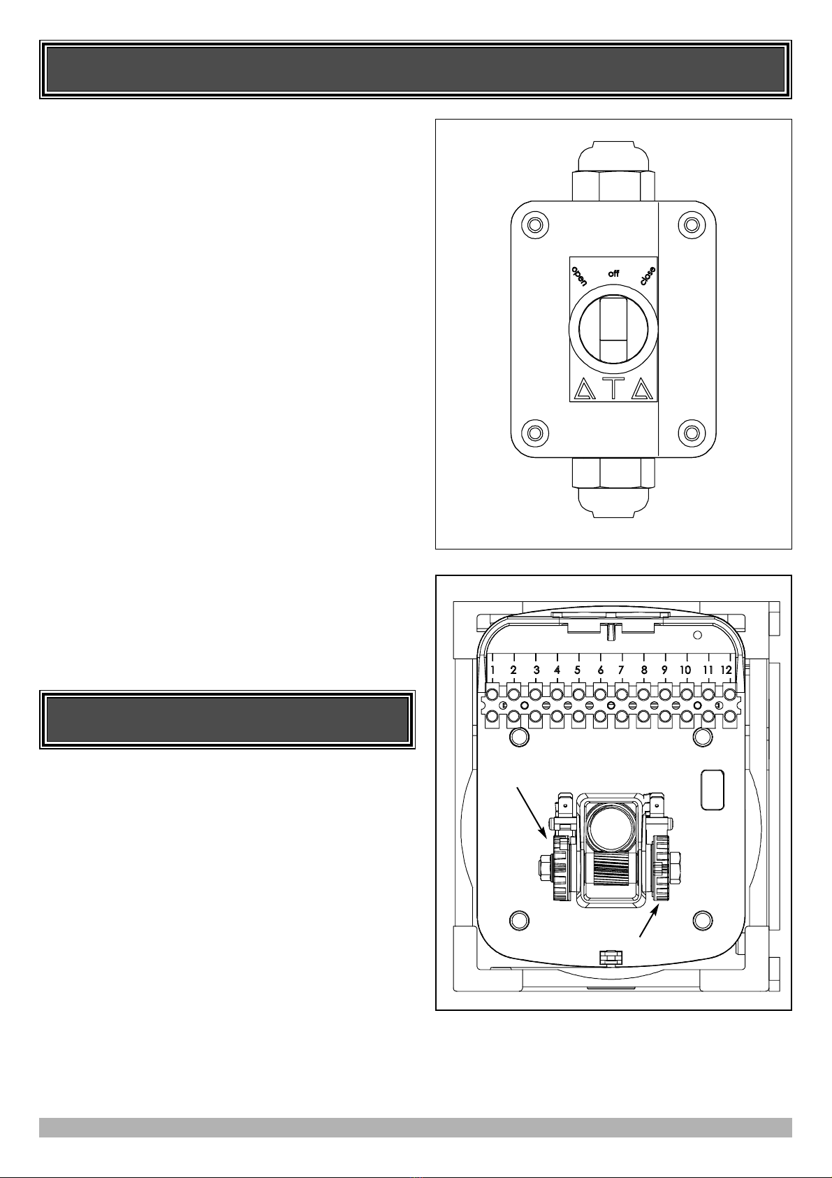
OPERATION
To operate the opener simply turn the pendant switch anti-
clockwise to open or clockwise to close the door. The open
position allows the door to open fully without having to
constantly hold the switch. For safety the close position requires
continuous contact.
MANUAL OPERATION
The opener is equipped with a unique manual operation device. If
the power to the opener is disrupted for any reason the clutch
disengages and the door can move manually via the manual chain.
When power is restored the clutch re-engages to allow automatic
operation.
FEATURES
DO NOT operate the opener unless the door is in full
view and free from objects such as cars and persons.
Make sure that the door has finished moving before
entering or leaving the driveway.
DO NOT operate the opener when persons are near the
door. Children must be supervised near the door at all
times when the opener is in use. SERIOUS
PERSONAL INJURY and/or property damage can
result from failure to follow this warning.
DO NOT allow children to operate the opener.
SERIOUS PERSONAL INJURY AND/OR
PROPERTY DAMAGE can result from failure to
follow this warning.
Frequently examine the installation, in particular guides
and mountings for signs of wear, damage or imbalance.
DO NOT use if repair or adjustment is needed since a
fault in the installation or an incorrectly balanced door
may cause injury.
The opener is not showerproof - it should not be
immersed in water or sprayed directly by a hose or other
water carrying device.
The door must be WELL BALANCED. and in good
working order. A faulty door must be repaired by a
qualified technician prior to opener installation.
REMOVE OR DISENGAGE all locks and
mechanisms prior to installation of the opener.
Keep hands and loose clothing CLEAR of the door and
opener at all times.
Make sure that the door is fully open before driving into
or out of the driveway. And make sure the door is fully
closed before leaving the driveway.
The opener is not intended for use by young children or
infirm persons without adequate supervision. Children
should be supervised to ensure that they do not play with
the opener.

PRODUCT DESCRIPTION
4
DRIVE UNIT INSTALLATION
The ATA Axess Roller Shutter Opener consists of
one drive unit, and pendant switch.
PENDANT SWITCH
Housed in a commercial grade heavy duty enclosure is a
momentary contact switch. A standard 240V AC power outlet is
required to power the system. The enclosure meets the IP55
standard for ingress of dust and water.
MECHANICAL DRIVE UNIT
The drive unit consists of a powerful 240V single phase motor,
rugged gearbox and position encoder. It inlcudes a cluth
mechanism to allow easy manual operation and is rated to IP42
standard.
The ATA Axess Roller Shutter Opener is designed to operate
most commercial and heavy duty slat roller shutter doors. The
doors must be in good working condition and travel freely in the
guides.
INITIAL CHECK
Before commencing installation check the following:
1. The door moves freely for the full travel in both directions.
2. The mounting must be solid construction (concrete, brick or
steel. It must be able to withstand the full force applied to the
door.
3. There is a 240V 10Amp power point located within 1 metre of
pendant switch.
FIG. 1
FIG. 2

5
DRIVE UNIT INSTALLATION
MOUNTING THE DRIVE UNIT
The mounting plate holes are slotted for fine adjustment of the
output gear position. Follow the procedure below to ensure final
adjustments can be made later.
1. Determine on which side of the door the opener is to be
mounted.
2. Install manual chain guide as required.
3. Mount the base plate to door bracket either by welding in
place or using M12 hex bolts, washers and nuts.
4. Position opener and secure with M10 fasteners.
5. Mount drive sprocket on shaft in line with door drive gear.
6. Shorten drive chain as required and fit around drive gears.
7. Feed manual chain through guide and over pulley.
8. Shorten chain as required and fix ends to make a loop.
FIG. 4
FIG. 3
Door Drive Gear
Drive Chain
Manual Chain Guide
Mounting Plate

6
INITIAL ELECTRICAL INSTALLATION
CAUTION:
CABLES WHICH HAVE A GREEN/YELLOW COLOURED INSULATION ARE FOR
EARTHING PURPOSES ONLY. NEVER USE THESE CABLES FOR ANY OTHER PURPOSE.
SELECTING LEFT OR RIGHT HAND INSTALLATION.
Using the figure below, place the motor connector for the drive
unit so as to reflect the side of the doorway that it is installed.
NOTE: The wiring diagram on Page 7 is for right hand
installation. If left hand installation is required - interchange the
brown and white either inside the pendant switch.
Left Hand Right Hand
FIG. 5 FIG. 6

7
WIRING DIAGRAM - LEFT HAND INSTALLATION
0
0
1
1
2
2
3
3
4
4
5
5
6
6
7
7
8
8
9
9
10
10
11
11
12
12
13
13
14
14
AA
B B
C C
D D
E E
F F
G G
H H
I I
J J
S3(INTLK)
S3(INTLK)
N/C
S2(OPN)
S1(CLS)
S2(OPN)
S1(CLS)
DRIVE UNIT
#92242
LIMITS
J1
S1
S2
S3
PENDANT SWITCH BOX
BX1-ATA-SS
M
EARTHING
N/C
CLUTCH
INTERLOCK
SWITCH
L
N
E
BROWN
BLUE
GREEN/YELLOW
WHITE
BROWN
BLUE
G/YG/Y
BLUE
BROWN
RED
BROWN
WHITE
BLUE
G/Y
WHITE
BROWN
240V, 50Hz
OPENCLOSE
J1
SW1
J2
J2
YELLOW
RED
ORANGE
BROWN
BROWN
BLUE
BLUE
BLACK
BLUE
12
11
10
9
8
7
6
5
4
R A2
S A1
T N
NOTE: Wiring as shown are for left hand installation.
BLUE
BROWN
WHITE
BLUE
BROWN
WHITE
ATA-MOTOR
240V,1HP
THREE POSITION
PENDANT SWITCH

8
WIRING DIAGRAM - RIGHT HAND INSTALLATION
0
0
1
1
2
2
3
3
4
4
5
5
6
6
7
7
8
8
9
9
10
10
11
11
12
12
13
13
14
14
AA
B B
C C
D D
E E
F F
G G
H H
I I
J J
S3(INTLK)
S3(INTLK)
N/C
S2(OPN)
S1(CLS)
S2(OPN)
S1(CLS)
DRIVE UNIT
#92242
LIMITS
J1
S1
S2
S3
PENDANT SWITCH BOX
BX1-ATA-SS
M
EARTHING
N/C
CLUTCH
INTERLOCK
SWITCH
L
N
E
BROWN
BLUE
GREEN/YELLOW
WHITE
BROWN
BLUE
G/YG/Y
BLUE
BROWN
RED
BROWN
WHITE
BLUE
G/Y
WHITE
BROWN
240V, 50Hz
OPENCLOSE
J1
SW1
J2
J2
YELLOW
RED
ORANGE
BROWN
BROWN
BLUE
BLUE
BLACK
BLUE
12
11
10
9
8
7
6
5
4
R A2
S A1
T N
NOTE: Wiring as shown are for right hand installation.
BLUE
BROWN
WHITE
BLUE
BROWN
WHITE
ATA-MOTOR
240V,1HP
THREE POSITION
PENDANT SWITCH

9
SETTING TRAVEL LIMITS
SETTING DOOR TRAVEL LIMITS
Note: Door should be moved manually to half open position.
1. Turn pendant switch anticlockwise to move door to desired
open position (Fig. 7).
2. If desired position is reached and green OPEN limit cam is not
in contact with limit switch, adjust cam until limit switch
“clicks”.
Note: If green limit cam activates switch before desired open
position is reached, then rotate cam clockwise, then turn pendant
switch to open position to continue travel to desired open position.
Repeat step 2 above if necessary.
3. Turn pendant switch clockwise to move door to desired closed
position.
4. If desired position is reached and red CLOSE limit cam is not
in contact with limit switch, adjust cam until limit switch
“clicks”.
Note: If red limit cam activates switch before desired close
position is reached, then rotate cam anticlockwise, then turn
pendant switch to close position to continue travel to desired close
position. Repeat step 4 above if necessary.
FIG. 8
GREEN OPEN
LIMIT CAM
RED CLOSE
LIMIT CAM
FIG. 7
SPECIFICATIONS
TECHNICAL SPECIFICATIONS
INPUT VOLTAGE: 240V AC 50Hz Single Phase
MOTOR TYPE: Induction
MOTOR VOLTAGE: 240V Single Phase
MOTOR RATING: 1 H.P. (0.75kW)
MAXIMUM DOOR SIZE: 18m2
MAXIMUM DOOR HEIGHT: 4700mm (11-Tooth Sprocket)
MAXIMUM DOOR HEIGHT: 6000mm (14-Tooth Sprocket)
DRIVE UNIT WEIGHT: 23Kg
PENDANT SWITCH WEIGHT: 0.5Kg
Please Note: Specifications are subject to change without notice.

10
DATE MAINTENANCE PERFORMED BY SIGNATURE AMOUNT INV. No.
MAINTENANCE RECORD
MAINTENANCE
RECOMMENDED MAINTENANCE
The door and opener should be inspected and serviced at
regular intervals based on usage. The table at right indicate
ideal maintenance schedules based on duty cycle.
The following elements should be examined at each service:
zDoor rolls freely.
zDoor guides in good condition.
zDoor stops correctly.
zNo oil leak from opener gearbox.
zOpener retaining bolts secure.
zOpener is clean (no debris or insects, etc.).
zInsect surface spray around opener (not electronics).
zInspect electrical connections.
zLimit switches engage correctly.
zExternal safety devices operate correctly.
zGeneral operationis satisfactory.
DAILY DUTY
CYCLES
RECOMMENDED
MAINTENANCE
Over 150 every 1 month
100 - 150 every 2 months
50 - 99 every 4 months
20 - 49 every 6 months
Under 20 every 12 months

PARTS LIST
WHEN ORDERING SPARE PARTS
PLEASE QUOTE THE ORDER
CODE NUMBER TO YOUR
INSTALLER/DISTRIBUTOR

WARRANTY AND EXCLUSION OF LIABILITY
1. This warranty is an addition to any non-excludable conditions or warranties that are implied into this contract by relevant statute,
including the Trade Practices Act 1974 (Cth).
2. Subject to all of the matters set out below, Automatic Technology Australia Pty Ltd ("ATA") warrants:
(a) the Axess Pro Series Opener for twelve (12) months,
(b) all components and accessories for twelve (12) months,
from the date of purchase (specified in the sales docket receipt) as free of any defects in material and workmanship.
3. This warranty applies only where the purchaser:
(a) immediately notifies ATA or the retailer of the alleged defect;
(b) returns the product to the retailer; and
(c) presents the relevant sales docket and this warranty document to the retailer to confirm the date of purchase.
4. Except for this warranty, ATA gives no warranties of any kind whatsoever (whether express or implied), in relation to the product,
and all warranties of whatsoever kind relating to the product are, to the extent permissible by statute, hereby excluded.
5. To the extent permissible by statute, ATA disclaims any liability of whatsoever nature in respect of any claim or demand for loss
or damage which arises out of:
a) accidental damage to or normal wear and tear to the product or to the product's components;
b) any cost relating to damage resulting from wear and tear;
c) blown fuses, loss or damage caused by electrical surges, power surges or power spikes;
d) loss or damage due to theft, fire, flood, rain, water, lightning, storms or any other acts of God;
g) door surface area exceeding 18m2;
h) door or gate not in safe and correct working order and condition;
i) evidence of unauthorised repairs;
j) any cost relating to damage caused by misuse, negligence or failure to maintain the equipment in a proper working
order as per clauses (d) through (i);
k) installation, adjustment or use which is not in accordance with the instructions set out in installation instruction manual;
l) attempted or complete modification or repairs to the product carried out by a person who is not authorised or has not been
trained by ATA to carry out such modification or repairs;
m) faulty or unsuitable wiring of structure to which the product is fixed or connected;
n) radio (including citizen band transmission) or any electrical interference;
o) damage caused by insects;
p) loss or damage to any property whatsoever or any loss or expense whatsoever resulting or arising there from or any
consequential loss;
q) any cost or expense arising due to manufacturer recall of any product;
r) any cost or expense due to negligence of the approved service provider;
6. ATA's liability under this warranty is limited, at ATA's absolute option, to replacing or repairing the product which ATA, in its
unfettered opinion, considers to be defective either in material and/or workmanship or to credit the dealer with the price at which
the product was purchased by the dealer.
7. This warranty does not extend to cover labour for installation.
8. This warranty is limited to Return-to-Base (RTB) repair and does not cover labour for on-site attendance.
9. This warranty is void if the Product is not returned to the manufacturer in original or suitably secure packaging.
10. This warranty is only applicable for repairs to the product carried out within Australia.
11. This warranty does not cover consumable items including globes, batteries and fuses.
12. This warranty is not transferable.
13. Where the Product is retailed by any person other than ATA, except for the warranty set out above, such person has no authority
from ATA to give any warranty or guarantee on ATA's behalf in addition to the warranty set out above.
Notes:
1. One (1) cycle = one (1) open and one (1) close action of the door.
2. This warranty is to be read in conjunction with the owner's copy of the installation instruction manual.
AUTOMATIC TECHNOLOGY AUSTRALIA PTY LTD
ABN 11 007 125 368
17-19 Advantage Rd, Highett, Victoria, Australia 3190
Tel: +61 3 9532 2788 Fax: +61 3 9532 2799
© November 2005 Automatic Technology Australia Pty Ltd. All rights reserved.
In an ongoing commitment to product quality ATA reserve the right to change specification without notice. E&OE. Printed For Export.
Table of contents
Other ATA Gate Opener manuals
Popular Gate Opener manuals by other brands

Chamberlain
Chamberlain LA250EVK Operator's & installation manual

Nice
Nice TOO3000 User & installation manual

Platinum Access Systems
Platinum Access Systems BLSW1016 Installation instruction and owenrs manual

SOMFY
SOMFY Freevia 280 manual

FAAC
FAAC 413 Series user guide

Beninca
Beninca DU.IT14N User's handbook and spare parts catalogue for the installer