manuals.online logo
Brands
  1. Home
  2. •
  3. Brands
  4. •
  5. AT&T
  6. •
  7. Inverter
  8. •
  9. AT&T Z129A User manual

AT&T Z129A User manual

This manual suits for next models

1

Popular Inverter manuals by other brands

Omnik New Energy Omniksol-1.5k-TL user manual

Omnik New Energy

Omnik New Energy Omniksol-1.5k-TL user manual

Agilent Technologies 33250A user guide

Agilent Technologies

Agilent Technologies 33250A user guide

4-noks ZR-SWITCH-RC instruction manual

4-noks

4-noks ZR-SWITCH-RC instruction manual

V&T V5 Series user manual

V&T

V&T V5 Series user manual

Hon Turing HT-T-S1000-12 introduction

Hon Turing

Hon Turing HT-T-S1000-12 introduction

Metabo E 140 SP Plus Original operating instructions

Metabo

Metabo E 140 SP Plus Original operating instructions

BARRON EXITRONIX Tucson Micro Series installation instructions

BARRON

BARRON EXITRONIX Tucson Micro Series installation instructions

Baumer HUBNER TDP 0,2 Series Mounting and operating instructions

Baumer

Baumer HUBNER TDP 0,2 Series Mounting and operating instructions

electroil ITTPD11W-RS-BC Operation and Maintenance Handbook

electroil

electroil ITTPD11W-RS-BC Operation and Maintenance Handbook

Silicon Solar TPS555-1230 instruction manual

Silicon Solar

Silicon Solar TPS555-1230 instruction manual

Mission Critical Xantrex Freedom SW-RVC owner's guide

Mission Critical

Mission Critical Xantrex Freedom SW-RVC owner's guide

HP 3312A Operating and service manual

HP

HP 3312A Operating and service manual

Hoymiles HM-500T user manual

Hoymiles

Hoymiles HM-500T user manual

Nitecore SPM10 user manual

Nitecore

Nitecore SPM10 user manual

AEG Protect PV installation manual

AEG

AEG Protect PV installation manual

On Board TruePower Plus 1200MS owner's manual

On Board

On Board TruePower Plus 1200MS owner's manual

Plugreen PGM-200P-230 Installation and operation manual

Plugreen

Plugreen PGM-200P-230 Installation and operation manual

Fourgroup Easy use and Programming Handbook

Fourgroup

Fourgroup Easy use and Programming Handbook

manuals.online logo
manuals.online logoBrands
  • About & Mission
  • Contact us
  • Privacy Policy
  • Terms and Conditions

Copyright 2025 Manuals.Online. All Rights Reserved.

CIB 3019
Issue 1
PRINTED IN U.S.A.
Instructions for
(Z129A) RING GENERATOR UNIT
(61351)
Copyright © 1984 AT&T Technologies
All rights reserved
CIB 3019
Issue 1
CIB 3019
(Z129A) RING GENERATOR UNIT (61351)
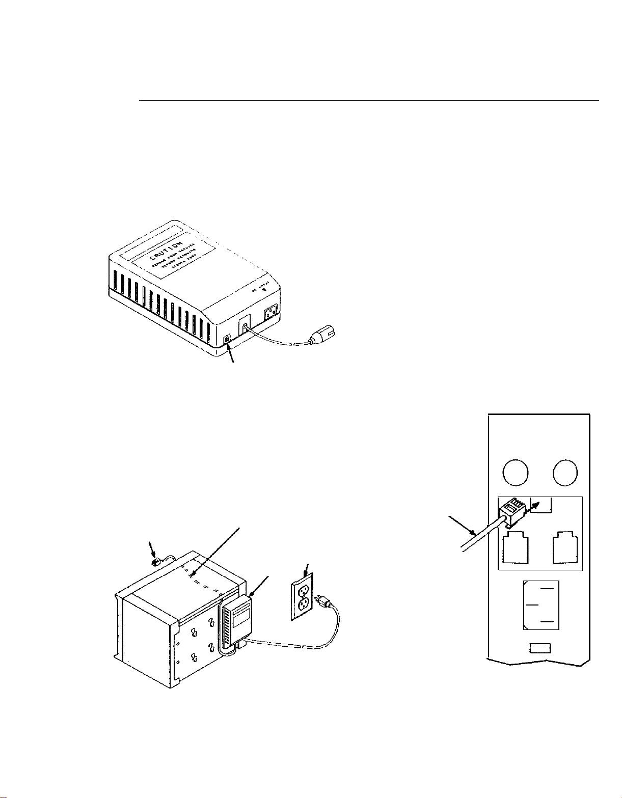
The ring generator (Figure 1) converts the 117-volt 60-Hz in-
put power to 117-volt 30-Hz ringing current. The ringing cur-
rent output is connected to the RING GEN. jack on the Power
Module in the Models 1030 and 3070 control units. This ring-
ing current is used for ringing basic telephones connected to
the Basic Telephone Module.
An ac power cord is included in the package with the ring
generator. The ring generator unit is identified on the label as
a 125H Frequency Generator.
RING SIGNAL
OUTPUT
(PRlMARY)
RING SIGNAL
OUTPUT (SECONDARY)
CORD STORED INSIDE
WHEN NOT IN USED
Figure 1
INSTALLATION
1 2
The ring generator unit has protective feet on the base for
mounting on a horizontal surface. Keyhole slots in the base
permit vertical mounting using a wall mounting bracket. For
Model 1030 and 3070 applications, the unit is mounted on
hangers on the back cover of the control unit. (See Figure 2.)
1.751.75
OUTPUT CORD Ring
Gen
TO RING GEN.
JACK ON POWER RING SIGNAL
MODULE OUTPUT CORD
1.
2.
3.
4.
5.
Align keyhole slots and hang ring generator unit on
hangers on back cover of control unit.
Run the ring signal output cord through and out the
opening under the top front rail of control unit. (See
Figure 2.)
Connect ring signal output cord into RING GEN. jack on
the Power Module. (See Figure 3.)
Note: When the expansion unit also contains a Basic
Telephone Module in slots 21, 22, 23, or 24,
connect the secondary output to the RING
GEN. jack on the Power Module in slot 16.
Never connect the two outputs from the ring
generator to both power moduIes in the expan-
sion unit.
Connect the power cord to the ac input connector on
the ring generator unit.
Connect the power cord to a 117-Vac outlet.
Operational Check
To test the ring generator, a Basic Telephone Module must be
installed in the control unit and at least one basic telephone
connected into the module.
Dial the intercom number of the basic telephone and confirm
that ringing occurs.
Power Module
RING SIGNAL
Circuit Breakers
Auxiliary
Power
117 VOLT
OUTLET
RING
GENERATOR
Power
Figure 2
Figure 3
Equipment manufactured by AT&T Technologies in the U.S.A.