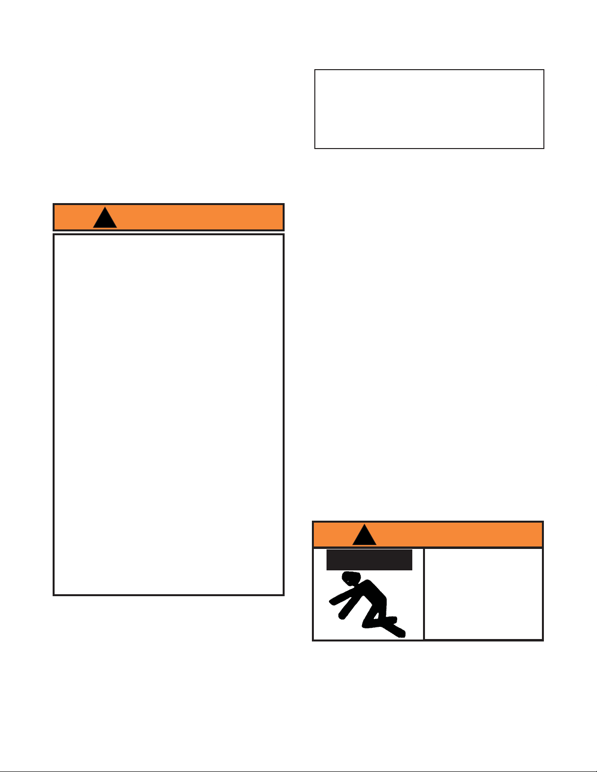
ATD Tools ATD-10141 User manual

Model Number
ATD-10141 Capacity
2 Ton
Owner’sManual
Engine Crane
Printed in China
ATD10141_rev_0417
ATDTools,Inc.
160 Enterprise Drive, Wentzville, MO 63385
Made in China to ATD Tools, Inc. Specications
Visit us at www.atdtools.com
WARNING: This product may contain chemicals, including lead, known to the State of California
to cause cancer, birth defects or other reproductive harm. Wash hands after handling.

2
Model Boom
Position Capacity BoomLength
ATD-10141
1
SPECIFICATIONS
Max.Hook HeightMin.Hook Height
1Ton
18-1/2"
10"
77-1/4"
88-1/4"
84-1/2"
80-3/4"
66-1/8"
4
"4/325noT2
59-1/2"14-1/8"1 1/2 Ton2
3
72-7/8"5-7/8"1/2Ton
PRODUCT DESCRIPTION
ATD Engine Crane is designed to safely lift and lower rated capacity engines. Welded steel tube construction, heavy
duty chain and safety hook, steel casters and wheels ensure safety, strength and stability.
Save these instructions. Foryoursafety, read, understand,andfollow the information provided withandonthisjack.
Theownerandoperatorofthisequipmentshallhaveanunderstandingofthisenginecraneandsafeoperatingprocedures
beforeattemptingtouse.Theownerandoperatorshallbeawarethatuseandrepairofthisproductmayrequirespecial
skills and knowledge. Instructions and safety information shall be conveyed in the operator's native language before
use of this jack is authorized. If any doubt exists as to the safe and proper use of this product, remove from service
immediately. Inspect before each use. Do not use if broken, bent, cracked or damaged parts are noted.Any crane
that appears damaged in any way, or operates abnormally shall be removed from service immediately. If the engine
crane has been or suspected to have been subjected to a shock load (a load dropped suddenly, unexpectedly),
immediatelydiscontinue use untilproduct has been checked by an authorized servicecenter. It is recommendedthat
anannualinspection be done byqualifiedpersonnel. Labels and OwnersManualsare available from manufacturer.
Boom extension
Rear caster
Middle
caster
Leg extensions
Upright
Support strut
Boom
Crane handle
Hydraulic unit
Chain/hook
assembly
Front caster
Handle
Base
Leg holder
Figure1-EngineCrane Nomenclature

3
Figure2 -Assembly Illustrationfor Model ATD-10141
ASSEMBLY
1.Attach two front casters (#1) to legs (# 3) with M8x12 bolts (# 2).
2.Attach two middle casters (#6) and two rear casters (#1) to base (#4) with M8x12 bolts (#2).
3. Slide two legs (#3) into the base (#4) and secure with M14x30 bolts (#8).
4.Attach upright (#7) to base (#4) with M14x100 bolts (#9), washers (#10) and nuts (#11).
5. Attach two strut supports (#12) to base (#4) and upright (#7) with M16x100 bolts (#13), washers (#14), and nuts
(#15).
6. Place hydraulic unit (#16) on upright’s support bracket and secure with M16 x 90 bolt (#17), washer (#18) and nut
(#19).
7.Attachboom(#20)to upright (#7) with M20x100bolt (#21), washer (#22), andnut (#23).
8. Pump jack until ram is extended approximately 2”.
9.Allign the hole on the hydraulic ram with the mounting hole of boom and secure with the lock pin (#24) and retainer
clip(#25).
10. Slide boom extension (#26) into boom (#20) and secure with the lock pin (#24) and retainer clip (# 25).
11.Attachchain/hookassembly(#30) to boomextension (#26) with M14x80 bolt(#27), washer (#28) and nut(#29).
12.Attach handle to upright with four M8x12 bolts (#31).

Toavoidcrushingand
relatedinjuries:
NEVERwork on, under or
aroundaloadsupported
only by a crane.
Immediatelytransferthe
loadtoan appropriately
ratedenginestand.
!WARNING
!SAFETYMESSAGE!
Lift only on areas of the engine as specified by
thevehiclemanufacturer.
Be sure all tools and personnel are clear before
loweringload.
OPERATION
1. Load capacity should be coordinated with boom
extension and legs extension. Do not extend boom
extension beyond the marking that coordinate with
the legs extension.
2. Ensure application is compatible with product.
3.Secureenginetochain/sling hook assembly,ensuring
loadis centered.
4. Follow vehicle service manual recommendations to
remove engine. When ready to remove engine, turn
releasevalve clockwise untilfirm. Pump handleuntil
loadis high enough to clearvehicle.
5. Immediately upon removal and when clear of the
vehicle,lowertheloadtothelowestpracticalposition
byturning the release valve levercounter-clockwise
slowlyand carefully.
Note: Avoid rolling the loaded engine crane. To help
positionanenginestandifnecessary,moveonlyacross
smooth,level, seamless surfaces.
Before movingensure the load:
a. is lowered to the lowest practical position, but
alwaysbelow the center of gravity.
b.ispreventedfrom swinging and inadvertentshifting.
5. Position a suitable engine stand near the removed
engine, then immediately transfer the load to
appropriateenginesupportdevice(enginestand).
6.Checktoensurestandissecure before working on or
around.
BEFORE USE
1. Inspect crane before each use. Do not use if bent,
brokenorcrackedcomponentsare noted.Ensurethat
casters/wheelsandboommove freely. Check for and
tighten any loose assemblies.
2. Verify that the product and the application are com-
patible.
3. Before using this product, read the owner's manual
completely and familiarize yourself thoroughly with
the product and the hazards associated with its im-
properuse.
!WARNING
Study,understand,andfollowallinstructionsprovided
withandonthisdevicebeforeoperatingthisdevice.
Donotexceedratedcapacityforeachboomposition.
Use the device only on a hard, level surface.
These engine cranes are intended to be used to lift
andlowerrated capacity automotive andlight truck
engines. It is an aid in the removal and installation
ofautomotive and light truck engines.
Onlyuse chains and slings with a capacity equal to
orgreater thanthat of the crane.
If loaded crane must be moved, make certain that
load is stable, is in lowest possible position and is
movedoverasmooth,hardlevelsurface.
Avoidshockloadscausedbythe rapid opening and
closingofreleasevalve.
Shock loads may cause the load to swing, causing
thecrane to flip violently, bend or break.
Ensuretheboomisfullylowered before checking or
adding fluid to the hydraulic unit.
Never extend boom extension beyond furthest
distance of leg extension.
Do not stand over loaded boom nor in its intended
lineoftravel.
Do not use adapters or accessories that are not
providedinitially.
Do not use the device for any purpose other than
that for which it is intended.
Do not modify this device.
Failure to heed these markings may result in
personalinjuryand/orpropertydamage.
4

5
MAINTENANCE
Important: Use only a good grade hydraulic jack oil.
Avoid mixing different types of fluid and NEVER use
brake fluid, turbine oil, transmission fluid, motor oil or
glycerin.Improperfluidcancause failureofthejackand
thepotentialforsuddenandimmediateloss of load. We
recommendMobil13Morequivalent.
Adding oil
1.Carefullyremove hydraulic jack fromcrane.
2. With ram fully lowered and pump piston fully
depressed, set jack in its upright, level position.
Removeoilfillerplug.
3. Fill with oil until just below the rim of the oil filler
plug hole. Reinstall the oil filler plug.
Changing oil
Forbest performance and longestlife, replace the
completefluid supply annually.
1.Carefullyremove hydraulic jack fromcrane.
2. With ram fully lowered and pump piston fully
depressed, set jack in its upright, level position.
Removeoilfillerplug.
3. Lay the jack on its side and drain the fluid into a
suitablecontainer.
Note: Disposeof hydraulic fluidin accordance with
localregulations.
4. Set jack in its level upright position.
5. Fill with oil until just below the rim of the oil filler
plug hole. Reinstall the oil filler plug.
Lubrication
A periodic coating of light lubricating oil to pivot points,
axlesandhingeswillhelptopreventrustandassurethat
wheels,casters, and pumpassemblies move freely.
Cleaning
Periodically check the pump piston and ram for signs of
rustorcorrosion. Clean asneeded and wipe withan oily
cloth.
Note:Neverusesandpaperorabrasivematerialon
thesesurfaces !
Storage
1. When not in use, store the jack with pump piston
andram fully retracted.
2. To transform the crane into storage position:
a.Remove lock pin (#24on figure 2)from boom.
b. Lean hydraulic unit back against upright and
slowly lower the boom to rest against hydraulic
unit.
c.Remove bolts(#8 on figure 2) of left and right legs
ofthe crane.
d. Remove legs from crane and keep it in the leg
holderat each side of upright.
Figure3 - Engine CraneStorage Position

TROUBLESHOOTING
PossibleCauses
Jack will not lift load
Jack *bleeds off after lift
Jack will not lift to full extension
• Release valve not tightly closed
• Overload condition
• Fluid level low
• Fluid level low
• Air trapped in system
• Release valve not tightly closed
• Overload condition
• Hydraulic unit malfunction
• Ensure release valve tightly closed
• Remedy overload condition
• Ensure release valve tightly closed
• Remedy overload condition
• Replace hydraulic unit
• Ensure proper fluid level
• With ram fully retracted, remove oil
filler plug to let pressurized air
escape, then reinstall oil filler plug.
Poor lift performance
Jack will not lower after unloading •Reservoiroverfilled • Drain fluid to proper level
Symptom Corrective Action
* "Bleeding off" means that jack begins to slowly lower rather than keep load at height.
6

YTQNOITPIRCSEDTRAP#TRAPGNIREDRO#METI
1MOOBA/N1
1NOISNETXEMOOB2-14101DTA2
1YLBMESSAKOOHDNANIAHCT-3202-233
1ELDNAHENARCA/N4
2TURTSTROPPUSA/N5
1THGIRPUA/N6
1ESABA/N7
2GELA/N8
2"3RETSACELDDIM90-14101DTA9
2"2/1-3RETSACRAER01-14101DTA01
2"2/1-3RETSACTNORF01-14101DTA11
1TINUCILUARDYHE-14101DTA21
LLA)STLOBDNASTUNLLA(TIKERAWDRAHA/N-
-)S(LEBALA/N-
-LAUNAMA/N-
Model ATD-10141
Figure 4 - Replacement Parts Illustration for Model ATD-10141
7
REPLACEMENT PARTS
Not all components of the crane are replacement items, but are illustrated as a convenient reference of location and
position in the assembly sequence. When ordering parts, give the model number, serial number and parts description.

8
ATD Tools, Inc.
160 Enterprise Drive
Wentzville, MO 63385
www.atdtools.com
ONE YEAR LIMITED WARRANTY
For a period of one (1) year from date of purchase, ATD Tools,Inc. will repair or replace, at its option, without charge,
any of its products which fails due to a defect in material or workmanship, or which fails to conform to any implied
warranty not excluded hereby.
Performance of any obligation under this warranty may be obtained by contacting your distributor or point of sale
for further instructions. Please retain your proof of purchase, as it will be needed for any claim.
Except where such limitations and exclusions are prohibited by applicable law, (1) the CONSUMER'S
SOLEAND EXCLUSIVE REMEDY SHALLBE THE REPAIR OR REPLACEMENT OF DEFECTIVE PRODUCTSAS
DESCRIBEDABOVE, and (2)ATD Tools,Inc. SHALLNOT BE LIABLE FORANY CONSEQUENTIALOR INCIDEN-
TALDAMAGE OR LOSS WHATSOEVER, and (3) THE DURATION OFANYANDALL EXPRESSEDAND IMPLIED
WARRANTIES, INCLUDING WITHOUT LIMITATION,ANY WARRANTIES OF MERCHANTABILITYAND FITNESS
FOR A PARTICULAR PURPOSE, IS LIMITED TO A PERIOD OF ONE (1) YEAR FROM DATE OF PURCHASE.
Some states do not allow limitations on how long an implied warranty lasts, so the above limitation may not apply
to you. Some states do not allow the exclusion or limitation of incidental or consequential damages, so the above
limitation or exclusion may not apply to you. This warranty gives you legal rights, and you may also have
other rights which vary from state to state.
Table of contents
Other ATD Tools Construction Equipment manuals
Popular Construction Equipment manuals by other brands

KBT
KBT 573.001.0 001 Series Instructions for use

Maeda
Maeda MC174 Operator's manual

Skylift
Skylift Mini-Derrick Super 6000 Low Pro Parts and maintenance manual

Snorkel
Snorkel 000003 Series Repair parts manual

ABS
ABS Guard OnTop Sandwich quick start guide

Altrad Belle
Altrad Belle Commodore Operator's manual