ATD Tools ATD2P11BS User manual

Jun 2017
ATD2P11BS
Two-Post Clear Floor
‘Bi-Symmetric’ Automotive Lift
11,000 lbs. Capacity
(2,750 lbs. Max per Arm)
Installation & Operation Manual

2
ATD2P11BS
Jun 2017
TABLE OF CONTENTS
1. Safety Information
1.1 Note, Caution and Warning
1.2 Important Information
1.3 Safety Instructions
2. Technical Manual
2.1 Product Description
2.2 Technica Data
3. Installation
3.1 Site Se ection
3.2 Surface Condition/ Foundation & Anchoring
3.3 Too s Required
3.4 Insta ation Procedure
3.5 Hydrau ic Scheme
4. Operation
4.1 Operation Instructions
4.1.1 Lift Preparation
4.1.2 Loading Lift
4.1.3 To Raise Lift
4.1.4 Whi e Using Lift
4.1.5 To Lower Lift
4.1.6 Un oading Lift
4.2 Maintenance Instructions
5. Exploded iew / Parts List
6. Troubleshooting Guide
7. Power Unit Priming
8. Warranty Policy

3
ATD2P11BS
Jun 2017
1. Safety Information
1.1 Note, Caution and Warning
This document uses the following terms - NOTE, CAUTION and WARNING - to alert you to special instructions,
tips, or hazards for a given procedure. Please familiarize yourself with the notations described below.
INDICATES IMPORTANT INFORMATION THAT REQUIRES SPECIAL ATTENTION, SUCH AS A
PROCEDURE FOR A SPECIFIC VEHICLE, OR TIPS ON OPERATING THE EQUIPMENT.
INDICATES THE POTENTIAL FOR DAMAGE TO EQUIPMENT, ACCESSORIES, OR THE VEHICLE
UNLESS YOU FOLLOW THE INSTRUCTIONS OR PROCEDURE EXACTLY.
INDICATES THE POTENTIAL FOR PROPERTY DAMAGE, PERSONAL INJURY, OR DEATH DUE TO
HAZARDS ASSOCIATED WITH THE EQUIPMENT, VEHICLE, OR ENVIRONMENT. DO NO PERFORM
ANY PROCEDURE UNTIL YOU HAVE READ AND UNDERSTOOD THE WARNING INSTRUCTIONS.
1.2 Important Information
1. Read this manual thoroughly before in talling, operating, or maintaining thi lift.
2. This lift is designed for indoor use only, and hould not be installed in a pit or depression.
. The floor on which the lift is to be installed must be 4-1/4” minimum thickne concrete, with a
minimum compre ive trength of 3,000 p i.
4. The lift has pecific electrical requirement as described in the Installation Instructions section of this
manual.
5. This lift has a minimum ceiling height requirement as described in the Installation Instructions section
of this manual.
6. Failure by the owner to provide the recommended helter, mounting urface, electrical upply, and
ceiling height could result in unsatisfactory lift performance, property damage, or personal injury.
7. The operation of the lift is permitted by authorized personnel only.

4
ATD2P11BS
Jun 2017
1.3 Safety Instructions
1. Do not raise a vehicle on the lift until the installation is completed as described in this manual.
2. Technicians should be trained to use and care for the lift by familiarizing themselves with this
instruction manual. The lift should never be operated by an untrained person.
3. Always position the arms and adapters properly out of the way before pulling the vehicle into, or out of
the bay. Failure to do so could damage the vehicle and/or the lift.
4. Do not overload the lift. The capacity of the lift is shown on cover of this document and on the lift’s
serial number tag.
5. Positioning the vehicle is very important. nly trained technicians should position the vehicle on the
lift. Never allow anyone to stand in the path of the vehicle as it is being positioned and never raise
vehicle with passengers inside.
6. Position the arms to the vehicle manufacturer’s recommended pickup points. Raise the lift until
contact is made with the vehicle. Make sure that the arms have properly engaged the vehicle before
raising the lift to a working height.
. Keep everyone clear of the lift when the lift is moving, the locking mechanism is disengaged, or the
vehicle is in danger of falling.
8. Unauthorized personnel should never be in the shop area when the lift is in use.
9. Inspect the lift daily. The lift should never be operated if it has damaged components, or is
malfunctioning. nly qualified technicians should service the lift. Replace damaged components with
manufacturer’s parts, or equivalent.
10. Keep the area around the lift clear of obstacles.
11. Never override the self-returning lift controls.
12. Use safety stands when removing or installing heavy vehicle components.
13. Avoid excessive rocking of the vehicle when it is on the lift.
14. To reduce the risk of personal injury, keep hair, loose clothing, fingers, and all body parts away from
moving parts.
15. To reduce the risk of electric shock, do not use the lift when wet, do not expose the lift to rain.

5
ATD2P11BS
Jun 2017
16. To reduce the risk of fire, do not operate equipment in the vicinity of open containers of flammable
liquids.
1 . Use the lift only as described in this manual, use only manufacturer’s recommended attachments.
18. Unusual vehicles, such as limousines, RV’s, and long wheelbase vehicles, may not be suitable for
lifting on this equipment. If necessary, consult with the manufacturer or the manufacturer’s
representative.
19. The troubleshooting and maintenance procedures described in this manual can be done by the lift’s
owner/employer. Any other procedure should only be performed by trained lift service personnel.
These restricted procedures include, but are not limited to, the following: cylinder replacement,
carriage and safety latch replacement, column replacement and overhead structure replacement.
20. Anyone who will be in the vicinity of the lift when it is in use should familiarize themselves with the
following Caution, Warning, and Safety related decals supplied with this lift, and replace them if they
are illegible or missing.

6
ATD2P11BS
Jun 2017
2. Technical Manual
2.1 Product Description
The ATD2P11BS 2-post hydraulic lift is a surface ounted, fra e contact lift incorporating the latest safety technologies.
Designed and anufactured for a lifting capacity of 11,000 lbs. (Max 2,750 lbs. per Lifting Ar ) and is fully capable for
lifting vehicles, vans and light trucks by safely holding the in an elevated position. The ATD2P11BS also incorporates
the Bi-Symmetric feature, which allows the Ar s to be configured for both asy etrical & sy etrical lifting
configurations.
The ATD2P11BS 2-post hydraulic lift consists of
a fixed structural unit (Crossbea and
Colu ns), the obile units (Carriages and Lift
Ar s), and the Hydraulic Power Syste and
Safety devices.
A. Cro beam
B. Column
C. Carriage
D. Lifting Arm
E. Power Unit
F. Overhead Safety Shut-Off Bar
G. Single Point Safety-Latch Relea e
2.2 Technical Data
Capacity
11,000 lbs. (Max 2,750 lbs. per Ar )
Height Overall
144”
Width Overall
w/ Power Unit
145-1/2”
Max
Lifting Height
71”
Max
Lifting Height w/ Tallest Adaptor
76-1/2”
Width Between Colu ns
116”
Min Pad Height
4”
Drive Thru Clearance
104”
Front Ar Reach
–
Min / Max
2 ” – 45”
Rear Ar Reach
–
Min / Max
41” – 57”
Power
220V, 20 Amp, 1 Phase

7
ATD2P11BS
Jun 2017
Fig. 1 – Front iew Spec.
POWER UNIT MUST BE INSTALLED ON THE PASSENGER SIDE. FAILURE TO DO SO CAN RESULT
WITH INTERFERECE BETWEEN THE POWER UNIT AND SHORT SWING ARM, THUS CAUSING
DAMAGE TO POWER UNIT.

8
ATD2P11BS
Jun 2017
Bi-Symmetric (Asymmetric & Symmetric) Configurations
Fig.2a –Top iew Spec.
Fig.2b - Base Size Spec.
NOTE:
Power Unit must be
mounted on
Passenger Side,
beside the long/rear
Swing Arm.

9
ATD2P11BS
Jun 2017
3. Installation
3.1 Site Selection
The hydraulic lift is designed only for indoor use Application in a room with explosion hazard is not permitted Setting
in a wet place, a car wash center for instance, is prohibited
3.2 Surface Condition / Foundation & Anchoring
The 2-post hydraulic lift should be installed on level ground The foundation must be 4-1/4” minimum thickness
concrete, with a minimum compressive strength of 3,000 psi Failure to meet the foundation requirement may cause
the lift instability or personal injury Installing on asphalt, soft clay floor or near the expansion gap is prohibited
FOUNDATION and ANCHORING REQUIREMENTS
1. Concrete shall have compression strength of at least 3,000 PSI and a minimum thickness of 4-1/4” in order to
achieve a minimum anchor embedment of 3-1/4”. NOTE: When using the standard supplied 3/4” x 5-1/2” long
anchors, if the top of the anchor exceeds 2-1/4” above the floor grade, you DO NOT have enough embedment.
2. Maintain a 6” minimum distance from any slab edge or seam. Hole to hole spacing should be a minimum 6-1/2”
in any direction. Hole depth should be a minimum of 4-1/4”.
3. DO NOT install on asphalt or other similar unstable surface. Columns are supported only by anchoring to floor.
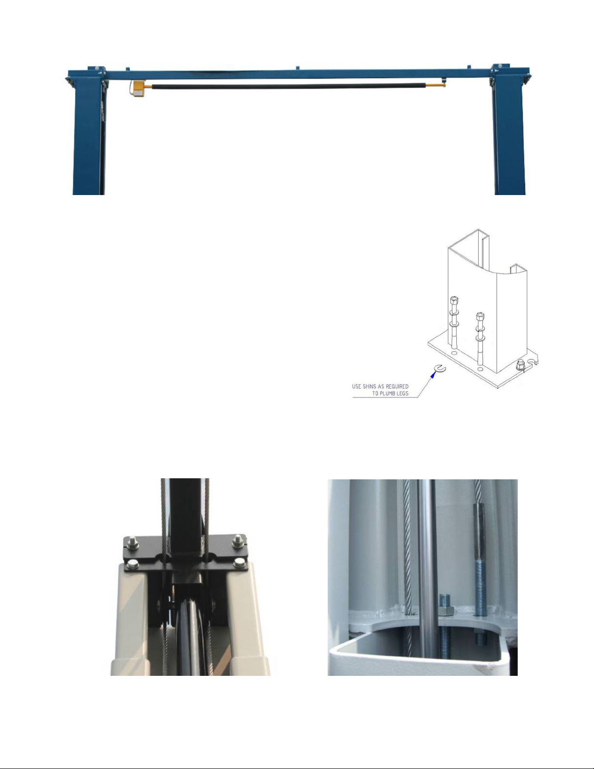
4. Using the horseshoe shims provided, shim each column base as required until each column is plumb. If one
column has to be elevated to match the plane of the other column, full size base shim plates should be used.
Torque anchors to 130 ft-lbs. Shim thickness MUST NOT exceed 1/2” when using the 5-1/2” long anchors
provided with the lift.
5. If anchors do not tighten to 130 ft-lbs. installation torque, replace the concrete under each column base with a
4’ x 4’ x 6” thick 3,000 PSI minimum concrete pad keyed under and flush with the top of existing floor. Allow
concrete to cure before installing lifts and anchors (typically 2 to 3 weeks).
ANCHORING TIPS
1. Use a concrete hammer drill with a carbide tip, solid drill bit the same diameter as the anchor, 3/4” -
(.775 to .787 inches diameter). Do not use excessively worn bits or bits which have been incorrectly sharpened.
2. Keep the drill in a perpendicular line while drilling.
3. Let the drill do the work. Do not apply excessive pressure. Lift the drill up and down occasionally to remove
residue to reduce binding.
4. Drill the hole to depth of 2” deeper than the length of anchor. NOTE: Drilling thru concrete (recommended) will
allow the anchor to be driven thru the bottom of foundation if the threads are damaged or if the lift will need to be
relocated.
5. For better holding power blow dust from the hole.
6. Place a flat washer and hex nut over threaded end of anchor, leaving the nut almost flush with the top of the
anchor bolt. Carefully tap anchor into hole. Do not damage threads. Tap anchor into the concrete until nut and
flat washer are against base plate. Do not use an impact wrench to tighten! Tighten the nut, two or three turns on
average after the concrete has cured (28-day cure). If the concrete is very hard only one or two turns may be
required.

10
ATD2P11BS
Jun 2017
FOUNDATION and ANCHORING REQUIREMENTS, Fig 3
Drill holes using 3/4” Clean hole. Run nut down just Tighten nut with
carbide tipped below impact section Torque wrench to
masonry drill bit per of bolt. Drive anchor 130 ft.-lbs.
ANSI standard into hole until nut and
B94.12.1977 washer contact base.
3.3 Tools & Equi ment Required
•12 quarts of Non-Detergent / Non-Foaming Hydraulic Oil - SAE-10, AW 32 or equivalent
•Chalk line and 12’ Tape Measure
•Concrete hammer drill with 3/4” bit
•11/16” open end wrench
•3/4” open end wrench
•Torque wrench
•15/16” deep socket or wrench
•1-1/8” socket
•13/16” open end wrench
•Level (18” minimum length)
•Vise grips
•Tape measure
•Funnel
•Hoist or Forklift (optional)
•Two 12’ step ladders
•1/4” drive ratchet with 5/16” socket

11
ATD2P11BS
Jun 2017
3.4 Installation Procedure
1. Read this manual thoroughly before installing, operating, or maintaining this lift.
2. Site E aluation and Lift Location:
A. Always use an architect’s plan when provided. Before unpacking the lift entirely, deter ine if the site is
adequate for the lift odel being installed see figures 1 & 2 for typical bay layout and ceiling height
require ents.
B. Snap chalk lines to identify the lift’s centerline.
C. Snap a chalk line parallel to the lift’s centerline, spaced 9.00” (230 ) toward the rear of the bay. This line
represents the back edge of the colu n bases.
D. Snap chalk lines parallel to the lift’s centerline spaced 68-7/8” (1,750 ) to the left and 68-7/8”
(1,750 ) to the right. These lines represent the APPROXIMATE outside edges of the colu n bases.
DO NOT USE THESE LINES TO POSITION THE COLUMNS, FOLLOW THE INSTRUCTIONS IN THIS
MANUAL.
3. Unpack the lift. Remo e the swing arms, bolt box, power unit box, and o erhead beam.
A. Sa e all packing hardware, as these co ponents are necessary to complete the installation.
B. Remo e the 1/2” bolts from the uprights which hold the two colu ns together.
C. Remo e the upper column. Do not stand the columns up now but lay the colu ns with their flat backs on
the floor.
4. Attach the cylinder mounts (uprights) using 4ea 1/2” x 1-3/4” bolts, washers and nuts pro ided as shown in figure
4a & 4b.
Fig. 4a Fig. 4b

12
ATD2P11BS
Jun 2017
5. Install Hydraulic Cylinders
A. Install the cylinder to the cylinder ounts (uprights) with 9/16” x 4-1/2” pins, cylinder bushings (spacer)
washers, and snap rings, as in figure 5a. The hose connecting port near the other end of the cylinder should
be positioned pointing to the colu n’s opening. (Fig. 5b)
B. Bolt the cylinder rods to the carriages. (Fig. 5c)NOTE: Make sure snap ring on cylinder rod is in groove.
Fig. 5a Fig. 5b Fig. 5c
DO NOT HOLD THE CYLINDER ROD IN A WAY THAT COULD DAMAGE THE FINISH. CYLINDER LEAKS CAUSED BY
DAMAGED RODS ARE NOT COVERD UNDER WARRANTY.
6. Columns Positioning & Main Side Column Anchoring
A. Carefully stand up the Main side column (w/ power unit bracket) & Off side column, position the colu ns
where they are to be secured. Ensure colu n’s openings are facing each other.
The Main side column must be positioned to be on the Passenger side or right side with the ehicle headed
forward. The distance between column back edge to wall, should be at least 2 feet for safety.
B. Using the colu n base as a te plate, drill the anchor bolt holes for the Main side column Only!
(Refer to FOUNDATION REQUIREMENTS & ANCHORING TIPS ON PAGES 9 & 10)
NOTE: DO NOT ANCHOR OFF SIDE COLUMN AT THIS TIME!
C. Install the anchor bolts, asse ble washers & nuts onto the anchor bolts. Thread the nuts onto the anchors
bolts where the tops of the nuts are just above the top of the anchor bolts. Carefully tap the anchor bolts
into the concrete until the washer rests against the base plate. Ensure not to damage threads.
D. Using a level, plu b the Main side colu n both side to side and front to back. Shi the leg as necessary
using the Shi s provided. Tighten anchor bolts to 130 ft. lbs. as noted on page 9. Re-check plu bness.
NOTE: Refer to FOUNDATION & ANCHOR REQUIREMENTS if more than 1/2” of shims are required.
E. Ensure Off side colu n is in the correct location. DO NOT DRILL HOLES FOR ANCHORS at this time.
7. O erhead Limit Switch & O erhead Beam (Fig. 6a, 6b & 6c)
A. Install overhead li it switch asse bly to overhead bea , using 2ea 1/4”-20 Bolt & Lock Nuts as shown in
figs 6a, 6b & 6c.
B. Slide end of padded bar (without a ounting hole) through the slot in the overhead switch asse bly.
Connect the padded bar to the inside hole in the overhead bea using a spacer and 1/4”-20 Bolt & Lock Nut

13
ATD2P11BS
Jun 2017
Fig. 6a Fig. 6b
Fig. 6c
8. Install o erhead beam to cylinder mounts (uprights) using 2ea 1/2” x 1-3/4” bolts, washers & nuts on each end,
(Figs. 7a, 7b, 7c). NOTE: Ensure o erhead Limit Switch Assembly is on the Main side column side.
Fig. 7a Fig. 7b

14
ATD2P11BS
Jun 2017
Fig. 7c
9. Anchoring Off Side Column
A. Using a level, check the align ent and plu bness of
the entire structure. Plu b the off side colu n both
side to side and front to back.
B. The base of the colu n ay vary fro the preli inary
layout, as it is ore i portant that the colu n be
perpendicular to the floor and parallel to the other
colu n.
C. Install the anchor bolts and shi the base as described
in Step #6
10. Equalization Cable Routing
A. The carriages should be resting on the sa e colu n latches for proper equalization. Ensure to easure the
height above the baseplate to each carriage. The easure ent should be within 3/8” of each other.
Fig. 8a Fig. 8b

15
ATD2P11BS
Jun 2017
B. Using the diagra s, rout the equalization cables according to Fig. 8a, 8b, 8c fro carriage to carriage
through the cable rollers. Secure to carriages using Nylon Hex Nuts & Washers. Ensure that cables are not
crossed together. Take out slack but DO NOT TIGHTEN CABLES AT THIS TIME.
C. After equalizations cables are routed and connected to carriages, take out the slack in both cables by
turning down the nuts on top of each carriage top. Use vise grips to hold the cable end, but be very careful
not to da age the threads.
NOTE: CARRIAGES MUST REMAIN AT THE SAME COLUMN LOCK HEIGHT POSITION WHILE CABLES ARE
BEING TIGHTENED. FAILURE TO DO WILL CAUSE THE CARRIAGES SAFETY LATCHES TO BE OUT OF SYNC.
D. Alternately tighten the cable nuts at both carriages until the cables are tightened. The correct tension in
the cables are indicated by being able to pull the cables together with approxi ately 15 lbs. effort at
idpoint in the colu n. If the cables are installed correctly, both carriages will raise together.
Fig. 8c - Cable Routing

16
ATD2P11BS
Jun 2017
11. Install the Hydraulic Fittings, Hoses and Return Lines
A. Fitting & Hose Connecting:
1.First screw on the hose fitting connectors on the cylinder’s lower end ports. (Fig. 9a)
2.Connect the longest hose fro the cylinder in Off side colu n to the top of Main side colu n.
Re e ber to route the hose through the hook on cross bea . (Fig. 9b & 9c)
3.Then fro the T-fitting inside colu n, connect the shortest length hose directly down to the ain
inside cylinder connector. (Fig. 9d)
4.Another iddle length hose fro the T-fitting goes to the otor pu p through a hole on the side of
the colu n. (Fig. 9d)
Fig. 9a Fig. 9b
Fig. 9c Fig 9d
B. Return Line Connection (blue air-line)
1.Screw in an elbow air-line fitting on the top end of the off side cylinder (Fig. 9b).
2.Screw in another T air-line fitting on the top end of ain side cylinder also. (Fig. 9c)
3.Connect the return line fro off side cylinder to ain side cylinder through fittings.

17
ATD2P11BS
Jun 2017
12. Mounting of the Power Unit
A. Mount on the otor pu p using 5/16” x 1-1/4” bolts and
nylon nuts provided in the bolt box to Main side colu n.
B. Connect the hose and the ‘blue’ Return Line to the pu p
valve block as shown in ( Fig 10)
13. Latch-release cable wiring and accessories mounting.
A. Mount the safety latch device on each colu n as shown in
( Fig. 11a & 11b)
Fig. 10
Fig. 11a Fig. 11b

18
ATD2P11BS
Jun 2017
B. Mount the Cable Pulley and support bracket on the top of the colu ns. (Fig. 11c)
Fig. 11c
C. Route and adjust the cable tension so that when the handle is pressed down, both latch will be released.
D. Put on the covers of the latch device. (Fig 12a & 12b)
Fig. 12a Fig. 12b

19
ATD2P11BS
Jun 2017
14. Install Lifting Arms
A. Position the gears with pin against the botto of the ar s in the orientation shown in Fig.13a. Attach the
gears to the ar s with bolts. Do not tighten at this ti e.
Fig. 13a Fig. 13b
B. Position the restraint pawls on the carriage to ate with the gears on the ar s.
C. Install the swing ar s and pins.
Suggestion:
The longer ar s go to the rear or drive-in side of the lift, and the short ar s go to the front.
DON’T FORCE THE GEARS, IT MAY BE NECESSARY TO PULL UP ON THE RESTRAINT ACTUATOR PIN
IN ORDER TO INSTALL THE SWING ARM PIN.
D. Tighten the gear bolts to 30 – 34 ft. lbs.
E. Asse ble the ar extensions and lifting pads. Li it ar extensions with bolts & nuts. ( Figs. 14a & 14b)
Fig. 14a - Front Arm
Lifting Pad

20
ATD2P11BS
Jun 2017
Fig. 14b - Rear Arm
15. Fill the Tank
.
Re ove the vent plug fro the power unit and fill the reservoir with hydraulic oil. Make sure the funnel used to fill
the power unit is clean. Fill with Non-Detergent / Non-Foa ing Hydraulic Oil - SAE-10, AW 32 or equivalent.
Replace the vent plug. The unit holds approxi ately ten quarts of fluid.
16. Lubricate the four inside corners of both columns with hea y duty grease.
17. Electrical Connection to POWER UNIT & OVERHEAD LIMIT SWITCH
A. Have a certified electrician ake the electrical connection to the power unit. Use separate circuit for each
power unit, as shown below in the Wiring Diagra .
IMPORTANT! The wiring must comply with local code. Protect each circuit with time delay fuse or circuit brea er.
For 208V-230V single phase, use 20 amp fuse.
WARNING!! Never operate the motor in line voltage less than 208VAC as motor damage may occur.
B. Have a certified electrician ake the electrical connection for the K2 overhead li it switch to power unit’s
switch box, as shown below.
Table of contents
Other ATD Tools Lifting System manuals

ATD Tools
ATD Tools ATD-7321A User manual

ATD Tools
ATD Tools ATD4P8D Operating instructions

ATD Tools
ATD Tools ATD-7489 Instructions for use

ATD Tools
ATD Tools ATD-7478 User manual

ATD Tools
ATD Tools ATD-7461A Service manual

ATD Tools
ATD Tools 6557 User manual

ATD Tools
ATD Tools 7392A User manual

ATD Tools
ATD Tools 4P9DXL Operating instructions

ATD Tools
ATD Tools ATD-7425A User manual

ATD Tools
ATD Tools ATD-10141A User manual