Poweramp CentraAir User manual

POWERAMP®• Division of Systems, Inc. • W194 N11481 McCormick Drive • Germantown, WI 53022
Printed in U.S.A.
Copyright © 2015
Manual No. 4111-0034
May 2015
CentraAir®
PATENT PENDING
Dock Leveler
Owner’s / User’s Manual

Page
Safety
Recognize Safety Information ............................................................. 1
General Operational Safety Precautions............................................ 1
Operational Safety Precautions........................................................... 2
Maintenance Safety Precautions......................................................... 4
Safety Decal’s........................................................................................ 5
Owner’s User’s Responsibilities......................................................... 6
Introduction
General Information, Dock Leveler Stock Specifications................. 7
Dock Leveler Stock Specifications..................................................... 7
Component Identification..................................................................... 8
Theory................................................................................................... 8
Installation
Prepare Pit............................................................................................. 9
Prepare Dock Leveler.......................................................................... 10
Install Dock Leveler............................................................................. 12
Install Control Panel and Wiring ........................................................ 16
Placard Installation.............................................................................. 17
Air Line Installation.............................................................................. 18
Put New Leveler Into Service.............................................................. 22
Operation
Operating Instructions ........................................................................ 24
Ramp Loading/Unloading Instructions ........................................ 25
End Loading/Unloading Instructions ........................................... 26
Maintenance
Service Dock Leveler Safely............................................................... 27
Periodic Maintenance.......................................................................... 28
Adjustments
Adjust Lip Latch and Lip Actuator Springs ...................................... 31
Adjust Lip Stop .................................................................................... 32
Troubleshooting
Troubleshooting................................................................................... 35
Parts
Electrical............................................................................................... 36
Control Box .......................................................................................... 37
Air Control Valves................................................................................ 39
Below Dock Control............................................................................. 41
Pit Extension Kit .................................................................................. 42
Bellows and Regulator........................................................................ 43
Frame and Platform............................................................................. 44
Lip Activation ....................................................................................... 46
Weather Seal ........................................................................................ 47
Placard ................................................................................................. 48
Miscellaneous
Customer Information ......................................................................... 49
Warranty................................................................................ Back Cover
Table of Contents

1
4111-0034 — May 2015
SAFETY
Do not start the equipment until all unauthorized
personnel in the area have been warned and have
moved outside the operating zone.
Remove any tools or foreign objects from the operating
zone before starting.
Keep the operating zone free of obstacles that could
cause a person to trip or fall.
Read and understand the Owner’s/User’s manual and
become thoroughly familiar with the equipment and its
controls before operating the dock leveler
Never operate a dock leveler while a safety device or
guard is removed or disconnected.
Never remove DANGER, WARNING, or CAUTION
signs or Decal’s on the equipment unless replacing
them.
General Operational Safety
Precautions
Recognize Safety Information
Safety-Alert Symbol
The Safety-Alert Symbol identifies NOTICE safety
messages on equipment, safety signs, in manuals,
or elsewhere. When you see this symbol, be alert
to the possibility of personal injury or death. Follow
the instructions in the safety message.
The use of the word DANGER signifies the
presence of an extreme hazard or unsafe practice
which will most likely result in severe injury or
death.
The use of the word WARNING signifies the
presence of a serious hazard or unsafe practice
which may result in serious injury or death.
The use of the word CAUTION signifies possible
hazard or unsafe practice which could result in
personal injury.
The use of the word NOTICE is to draw attention
to a procedure that needs to be followed to prevent
machine damage.
NOTICE
Op
era
ting
Zo
ne
O
peratin
g Zon
e

24111-0034 —May 2015
SAFETY
Operational Safety PrecautionsOperational Safety Precautions
Learn the safe way to operate this equipment. Read and understand the
manufacturer's instructions. If you have any questions, ask your supervisor.
Stay clear of dock leveling device when transport
vehicle is entering or leaving area.
Do not move or use the dock leveling device if
anyone is under or in front of it.
Keep hands and feet clear of pinch points. Avoid
putting any part of your body near moving parts.
Chock/restrain all transport vehicles. Never remove
the wheel chocks until loading or unloading is
finished and transport vehicles driver has been
given permission to drive away.
Do not use a broken or damaged dock leveling
device. Make sure proper service and maintenance
procedures have been performed before using.
Make sure lip overlaps onto transport vehicles bed
at least 4 in. (102 mm).
Keep a safe distance from both side edges.

3
4111-0034 — May 2015
SAFETY
Do not use dock leveling device if transports
vehicles bed is too high or too low.
Do not overload the dock leveling device.
Do not operate any equipment while under the
influence of alcohol or drugs.
Do not leave equipment or material unattended on
dock leveling device.

44111-0034 —May 2015
SAFETY
ALWAYS disconnect electrical power source and
ground wire before welding on dock leveler.
DO NOT ground welding equipment to any hydraulic
or electrical components of the dock leveler. Always
ground to the dock leveler frame.
Failure to follow these instructions may result in
damage to dock leveler and/or serious personal
injury or death.
Always post safety warnings and barricade the
work area at dock level and ground level to prevent
unauthorized use of the unit before maintenance is
complete.
Hydraulic and electrical power must be OFF when
servicing the equipment. For maximum protection,
use an OSHA approved locking device to lock
out all power sources. Only the person servicing
the equipment should have the key to unlock the
device.
ALWAYS stand clear of dock leveler lip when
working in front of the dock leveler. Failure to do this
may result in serious personal injury or death.
DO NOT grind or weld if hydraulic fluid or other
flammable liquid is present on the surface to be
ground or welded
DO NOT grind or weld if uncontained hydraulic fluid
or other flammable liquid is present. Stray sparks
can ignite spills or leaks near the work area. Always
clean up the oil leaks and spills before proceeding
with grinding or welding.
Always keep a fire extinguisher of the proper type
nearby when grinding or welding.
Failure to follow these instructions may result in
serious personal injury or death.
Maintenance Safety Precautions
A maintenance prop permanently attached and
hinged to the unit with means for lock out/tag out
requirements (per OSHA 1910.147) is included
with each pit style dock leveler. In addition, it is
recommended and good safety practice to use an
additional means to support the dock platform and
lip anytime when physically working in front of or
under the dock leveler. This additional means may
include, but not limited to a boom truck, fork truck,
stabilizing bar or equivalent.

5
4111-0034 — May 2015
SAFETY
Safety Decal’s
Every 90 days (quarterly) inspect all safety labels and tags to
ensure they are on the dock leveler and are easily legible. If any
are missing or require replacement, please call 1-800-643-5424
for replacements. 1751-0727
DANGER
1751-0727 Rev A
CRUSH HAZARD
Maintenance prop must
support leveler behind bar.
Do not force maintenance
prop forward of bar to
support lip. Failure to
comply will result in death or
serious injury. Refer to
owner’s/user’s manual for
proper use.
DANGER
1751-0729 Rev A
CRUSH HAZARD
Do not work under dock leveler unless this maintenance prop has been secured in the upright
position. Failure to comply will result in death or serious injury. See owner’s/user’s manual for proper
procedures.
Rotate prop to maintenance
position.
Open the pin latch
and insert through the
maintenance prop housing.
Close the pin latch to secure
prop. Use every time dock
leveler is serviced. Failure to
comply will result in death
or serious injury.
DANGER
1751-0731 Rev A
CRUSH HAZARD
DANGER
1751-0726 Rev A
CRUSH HAZARD
DO NOT ENTER PIT unless dock leveler is
securely supported by maintenance prop. Place
barriers on driveway and dock floor to indicate
service work being performed. Failure to comply
will result in death or serious injury. Refer to
owner’s/user’s manual for proper maintenance
procedures.
1751-0729
1751-0731
1751-0726
Unsupported dock leveler
ramps can lower unexpectedly.
Before allowing vehicle to leave
the dock always:
!Ensure no equipment,
material or people are on
dock leveler.
!Return dock leveler to its
stored position at dock level.
Failure to follow posted instructions will result in death or serious injury.
SAFETY INFORMATION
Call 262.255.1510 for replacement placards, warning labels, or owner’s/user’s manuals.
DANGER
OPERATION 7. Stay clear of hinges and front and
1. Read and follow all instructions and sidesof moving dockleveler.
warnings inowner’s/user’s manual. 8. N e v e r u s e d a m a g e d o r
2. Use of dock leveler restricted to malfunctioning dock leveler. Report
trained operators problems immediately to supervisor.
3. Always chock trailer wheels or
engage truck restraint before MAINTENANCE/SERVICE
operating dock leveler or beginning to 1. Read and follow all instructions,
load or unload. warnings and maintenance
4. Never use hands or equipment to schedules in the owner’s/user’s
move ramp or lip manual.
5. Before activating dock leveler: 2. Maintenance/Service of dock leveler
!
Ensure trailer is backed in against restricted to trained personnel.
bumpers. 3. Place barriers on the driveway and
!
dock floor to indicate service work is
Remove any end loads if required.
!
being performed.
Check trailer alignment to avoid lip
4. DO NOT ENTER PIT unless dock
interference. If lip does not lower to
leveler is securely supported by
trailer bed, reposition vehicle.
maintenance prop.
6. Ensure truck bed supports extended
5. If electrically powered turn off and use
lip or leveler frame supports the ramp
OSHAlockout/tagout procedures.
before driving on ramp.
DO NOT
FORK THIS SIDE
FORK
HERE
1751-0730
(x2)
(decal placed in same position on both sides)
1751-0329
(x2)
1751-0330
(x2)

64111-0034 —May 2015
OWNER’S/USER’S RESPONSIBILITIES
1. The owner/ user should recognize the inherent dangers of the interface between the loading dock and
the transportation vehicle. The owner/ user should, therefore, train and instruct all operators in the safe
operation and use of the loading dock equipment in accordance with manufacturer’s recommendations and
industry standards. Effective operator training should also focus on the owner’s/user’s company policies
and operating conditions. Maintaining, updating and re training all operators on safe working habits and
operation of the equipment, regardless of previous experience, should be done on a regular basis and
should include an understanding and familiarity with all functions of the equipment. Owner’s/user’s shall
actively maintain, update and retrain all operators on safe working habits and operations of the equipment.
2. The manufacturer shall provide to the initial purchaser all necessary information regarding Safety
Information, Operation, Installation and Safety Precautions, Recommended Initial and Periodic Inspections
Procedures, Planned Maintenance Schedule, Product Specifications, Troubleshooting Guide, Parts
Break Down, Warranty Information, and Manufacturers Contact Information, as well as tables to identify
the grade(slope) for all variations of length or configuration of the dock leveling device and information
identifying the maximum uncontrolled drop encountered when sudden removal of support while in the
working range of the equipment.
3. It is recommended that when the transportation vehicle is positioned correctly in the dock opening and in
contact with both bumpers, there shall be a minimum of 4.00 inches (100mm) overlap of the leveling device
and the transportation vehicle at all times during the loading and unloading process.
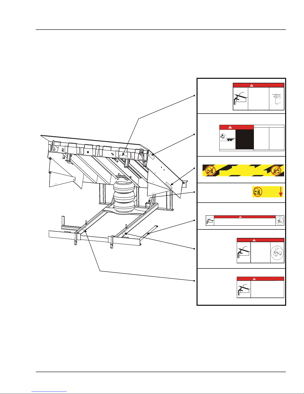
4. The Owner/User must review all name plates, placards, decals, instructions and posted warnings and
place the same in view of the operator or maintenance personnel for whom such warnings are intended
for. Contact manufacturer for any replacements.
5. Manufacturer’s recommended periodic maintenance and inspection procedures in effect at the date of
shipment shall be followed at all times. Written documentation of maintenance, replacement parts or
damage should be retained. In the event of damage notification to the manufacturer is required.
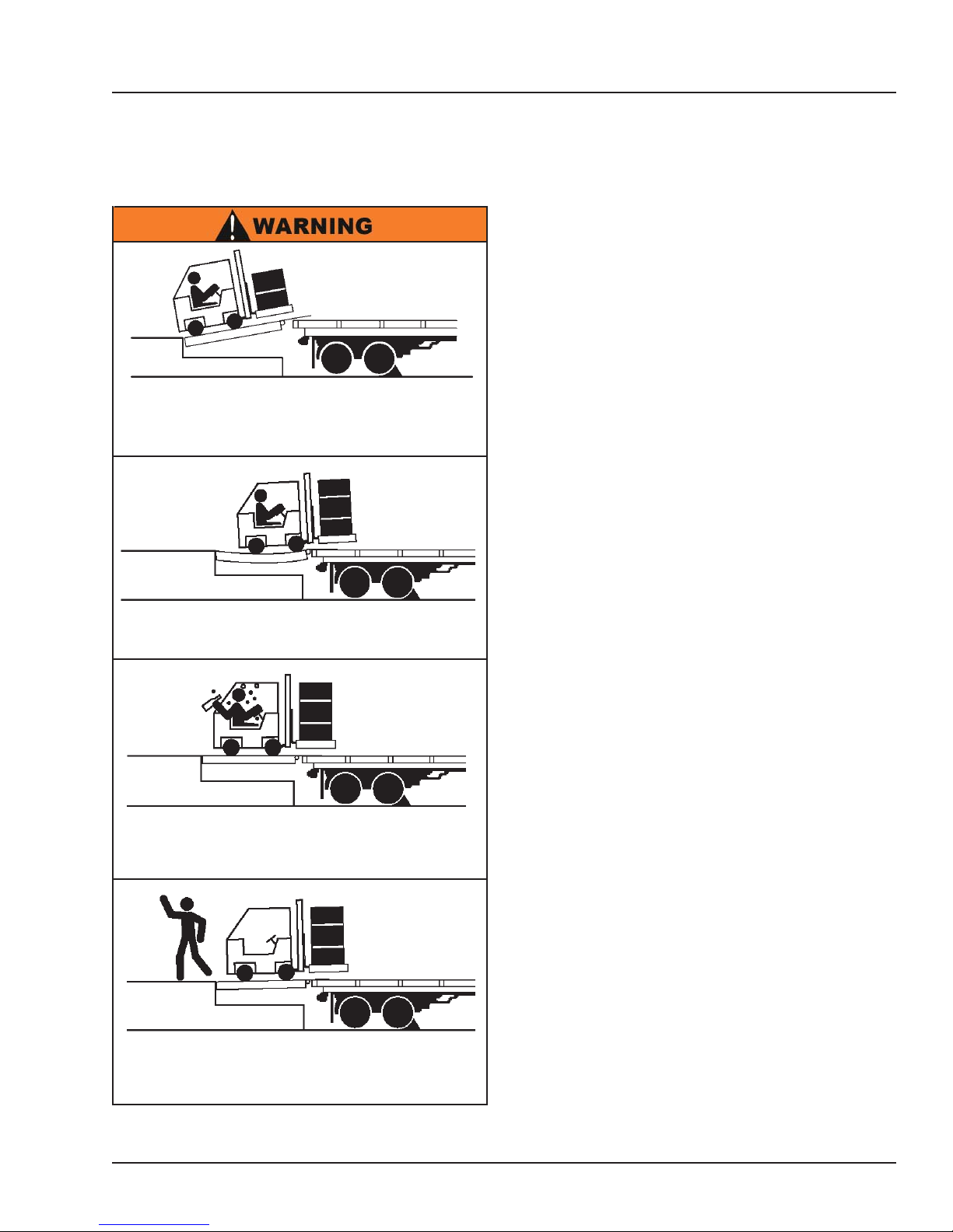
6. Loading dock equipment that has been structurally damaged or has experienced a sudden loss of main
support while under load (such as what might occur when a transport vehicle pulls out from under the
leveling device) shall be removed from service, inspected by a manufacturer’s authorized representative,
and repaired or replaced as needed before being placed back in service.
7. Any modifications or alterations of loading dock equipment shall only be done with prior written approval
from the manufacturer and the same shall be at least as safe as the original equipment was prior to the
modification and shall also satisfy all safety requirements of the manufacturer for the particular application
of the leveling device.
8. When industrial moving devices are being used in the loading or unloading of product from the
transportation vehicle, this vehicle shall have the brakes and wheel chocks applied appropriately or all
other positive restraining device shall be fully utilized. It is recommended that transport vehicles with air-
ride suspension systems shall have its air exhausted prior to performing loading and unloading operation
to minimize transport vehicle bed drop.
9. Loading dock safety equipment should never be used outside of its intended use, vertical working range,
or capacity. Please consult the manufacturer if you have any questions as to the use, vertical working
range or capacity of the equipment. Only properly trained and authorized personnel should operate the
equipment.
10. When selecting loading dock safety equipment, it is NOTICE to consider not only present requirements but
also future plans and any possible adverse conditions, environmental factors or usage.

7
4111-0034 — May 2015
INTRODUCTION
General Information
CentraAir®Series dock levelers are available in the
following sizes, weight capacities, and options:
Width:
6 ft (1828.8 mm)
6-1/2 ft (1981.2 mm)
7 ft (2133.6 mm)
Length
6 ft (1828.8 mm)
8 ft (2438 mm)
10 ft (3048 mm)
Capacity (CIR*)
25,000 lb (11 340 kg)
30,000 lb (13 608 kg)
35,000 lb (15 876 kg)
40,000 lb (18 144 kg)
45,000 lb (20 412 kg)
50,000 lb (22 680 kg)
* CIR (Comparative Industry Rating)
All docks are available in 115V Controls, pneumatic
push button or lanyard.
TheCentraAir®dock hasthreecontroloptions.Lanyard
cable, electrical control or pneumatic control, which
allows operation of the dock leveler functions. Each
CentraAir®leveler unit and control panel have been
factory assembled and tested to ensure satisfactory
operation.
To illustrate which connections are to be made in the
field at installation, electrical drawings and pneumatic
hose drawings are included with each order or by
contacting Poweramp Technical Services.
Once again, thank you and congratulations on your
purchase of a Poweramp CentraAir®dock leveler.
Dock Leveler Stock Specifications
Congratulations on your choice of a Poweramp®dock
leveler. This manual covers the CentraAir®dock
leveler.
Designed by Poweramp to be a marvel of simplicity and
efficiency, your dock leveler, when properly installed,
will provide many years of trouble-free performance
with an absolute minimum of maintenance. Its
revolutionary air bellows system efficiently controls
and operates every function. To obtain maximum
performance and longest possible use, a simple
program of preventive maintenance is recommended.
Q

84111-0034 —May 2015
Component Identification
A — Lip
B — Lip Assist Rod
C —Lip Linkage Assembly
D — Lip Latch Assembly
E — Lip Maintenance Prop Pivot
F — Lip Actuator Chain Spring
G — Lip Actuator Chain
H — Lip Actuator Chain Adjustment Link
(not shown)
I — Lip Keepers (2 used)
J — Air Bellows
K — Main Frame
L — Maintenance Prop
M —Toe Guard (2 used)
N —Raise Button (Electric)
O —Safety Legs
P —Air Control Valve
Q —Lanyard
R —Filter/Regulator -
Lubricator
S —Raise Button (Air)
T —Lip Assist Spring
The CA dock leveler uses Compressed Air with a lanyard
or (single push button) operation for ease of use.
The dock leveler can be operated three different ways.
1.) Depress RAISE button (N) on the control panel. This
activates an electric solenoid (P). The solenoid allows
compressed air into the air bellows causing the platform
to rise. When RAISE button is released the platform to
lower.
2.) Depress RAISE button (S) on the control panel.
Allows allows compressed air into the air bellows
causing the platform to rise. Releasing the RAISE button
allows the platform to lower.
3.)Pull up and hold the Lanyard (Q) chain in the rear
of the unit until platform and lip are fully extended.
Releasing the chain allows the platform to lower.
The regulator (R) supplies 95 psi to the bellows. (J)
When the platform rises to with in 2-3 in. (51-76. mm)
of its full raised height, the lip spring (F) and lip actuator
chain (G), causes the lip linkage assembly to push the
lip out and up.
The lip assist spring (S) also assist pushing the lip
out. When the lip is fully extended, the lip latch cable
engages the lip latch assembly, locking the lip in the
extended position. The dock leveler has reached its full
height when the lip is fully extended.
To lower the platform, release the lanyard (Q) or
RAISE button (N or S).
The platform will lower until the extended lip rests on
the transport vehicle. If the lip did not fully extend or
there is no transport vehicle at the dock the platform
will lower until one of the following conditions occur:
• Lip is resting in lip keepers (cross-traffic position).
• Leveler went to the below-dock position, lip folds
automatically, leveler rests on the safety legs
(below dock position).
• Leveler went to the below dock position with
operator holding the safety leg retract cable
(not shown), safety legs are retracted, lip folds
automatically causing dock to rest in the full below
dock position.
THEORY
INTRODUCTION
R
N
Q
P
K
E
G
AO
I
J
M
F
L
CS
D
SBT

9
4111-0034 — May 2015
INSTALLATION
Before lowering the dock leveler into the pit, the
following must be performed:
1. Remove all debris from the pit and sweep the pit
clean.
2. Check the entire dock leveler pit for proper
construction according to approved/certified pit
drawings. Make sure pit is square by making the
following measurements:
• Measure pit width distance (A) at both front
and rear of pit.
• Measure dock floor-to-pit floor distance (B) at
all four corners.
• Measure pit length distance (C) at both sides.
• Measure corner-to-corner (crisscross) distance
(D) at both sides. Take measurements at dock
floor level and at pit floor level.
If any measurement is off by more than 1/8
in. (3.18 mm), contact Poweramp®Technical
Services before proceeding.
When Required:
3. Make sure the field junction box for the dock leveler
(E) is at the correct location per pit diagrams.
4. Make sure the conduit for the air lines(E) are at
the correct location per the pit diagram
DO NOT remove the shipping bands around the
dock leveler lip until instructed to do so.
Post safety warnings and barricade the work area at
dock level and ground level to prevent unauthorized
use of the dock leveler before installation has been
completed.
Failure to follow the installation instructions can
result in damage to dock leveler, the facilities, and/
or serious personal injury or death.
Only trained installation professionals with the
proper equipment should install this product.
NOTICE
B
D
C
A
E
14"
10"
7"
7" E
Prepare Pit
A—Distance (Pit Width)
(Front and Rear)
B— Distance (Dock Floor-to-Pit
Floor) (All Four Corners)
C— Distance (Pit Length)
(Both Sides of Pit)
D— Distance (Pit Corner-to-Corner) (Top,
Bottom, and Both Sides)

10 4111-0034 —May 2015
1. Remove any control panel and bumpers that
may be banded to the frame of the dock leveler.
DO NOT remove the shipping bands (B) around
the platform lip and leveler frame at this time.
Poweramp®dock levelers are designed with installation
in mind. Each unit is shipped with lifting brackets (A)
fastened to the platform side joists.
Prepare Dock Leveler
NOTE: Overall width of platform and lifting brackets
(A) must be kept to a minimum to prevent
interference between the lifting brackets and
the pit walls as the dock leveler is lowered
into the pit.
2. Make sure the mounting hardware of lifting brackets
(A) is snug. The brackets should pivot relatively
freely on the mounting cap screw. DO NOT over
tighten.
3. Attach lifting chains to lifting brackets (A) and to
a lifting device (i.e., hoist or fork truck) having the
appropriate lifting capacity and reach.
4. Remove wood blocks that maybe attached to the
leveler frame before putting the dock leveler into
the pit.
5. Raise the leveler to allow the leveler sit on the
maintenance prop.
A— Lifting Bracket (2 used) B — Shipping Bands
INSTALLATION
Remove 3 plastic ties, 2 Rear, 1 Front before lowering into
pit
DO NOT over tighten the lifting bracket hardware.
Over tightening can damage the weather seal, if
equipped.
NOTICE
Compressor pump MUST be filled with
appropriate oil prior to initial start up.
Refer to manufactures manual for proper
maintenance procedure.
1751-1037
The dock leveler is heavy. Use a lifting device and
chains with the appropriate lifting capacity and
reach.
Always use the lifting brackets provided with the unit
whenever lowering or lifting a dock leveler into or out
of a pit.
Failure to follow these instructions may result in
damage to dock leveler and/or serious personal
injury or death.
CFM Leveler #s Recommended Compressor Size
7.3 3-6 1.5 HP 20 GAL @ 90 PSI
17.5 6 & up 5 HP 60 GAL @100 PSI
DO NOT remove the shipping bands (B) around
the platform lip and leveler frame at this time. The
shipping bands are needed to hold the leveler
together during the installation process.
NOTICE
A
B

11
4111-0034 — May 2015
INSTALLATION
This page intentionally left blank

12 4111-0034 —May 2015
INSTALLATION
Install Dock Leveler
A— Distance (Leveler Frame
Height)
B— Shim Locations (Under
Rear Vertical Supports)
C— Shim Location (Under
Lip Keepers)
D— Shim Locations (Under
Maintenance Prop)
E— Shim Locations (Under
Lip Spring)
F— Dock Floor
G— Rear Pit Curb Angle
H— String
I— Rear Hinge Frame Angle
J— Distance (Dock Floor-to-
Pit Floor)
K— Dock Leveler Frame
M — Pyramid (Preferred)
N— Stepped (Acceptable)
O— Offset (Not Acceptable)
P — Straight (Not Acceptable)
Q— Removable Frame Section
R— Shim Location (Bellows
Mounting Plate, Both
sides)
S— Shim Locations
T — Shim between lip keeper
curb angle when required.
M
N
O
P
Shim
Stacking Methods
C
D
Q
G
B
I
K
H
F
JA
R
E
S
T

13
4111-0034 — May 2015
NOTE: Poweramp®dock levelers are designed with a
nominal 1/2 in. (12.7 mm) shimming distance
to allow for pit inconsistencies.
1. Determine height of shim stack (B) for each shim
location (S) by performing the following:
a. Measure leveler frame height distance (A).
b. Measure dock floor-to-pit floor distance (J)
at each shim location (B). Write down the
dimensions obtained at each location.
c. Subtract distance (A) from distance (J) to obtain
the shim height. Repeat for each shim location.
5. Using an appropriate lifting device connected to
the lifting brackets, lower dock leveler into the pit
so rear hinge frame angle (I) is tight against rear
pit curb angle (G) across full width of the leveler
frame.
6. Allow rear of dock leveler to rest on the rear shims
while keeping the front of the dock leveler level with
the dock floor.
4. For all CentraAir®models, put a 1/4 in. (6.6 mm)
thick shim at locations (C,D and E).
NOTE: A 1/4 in. (6.6 mm) thick shim at locations (C,D
and E) is used only as a starting point. The
final shim stack height will be determined after
dock leveler is lowered into the pit.
2. Using the results obtained in step 1, create the
individual shim stacks on the pit floor at locations
(5). Build each shim stack (B) using the pyramid
method (M) (preferred) or stepped method (N) with
the top shim having a minimum size of 4-1/2 x 4-1/2
in. (114.3 x 114.3 mm) and each successive lower
shim being larger so the shims can be welded
together using a fillet weld. DO NOT use offset
method (O) or straight method (P).
NOTE: To assist in obtaining an accurate measurement
of distance (A), use a string (H) pulled tight
across the pit opening, directly over the shim
locations.
3. Verify that each shim stack is at the correct height
by measuring distance (A) [top of shim stack (B) to
dock floor].
INSTALLATION
The minimum size of the shim that contacts the
leveler frame (i.e., the top shim of each shim stack)
must be at least 4-1/2 x 4-1/2 in. (114.3 x 114.3 mm)
to support the full width of the hoist cylinder / storage
prop weldment.
Use the thickest shim stock possible for stability and
weld penetration purposes. DO NOT use multiple
layers of 1/8 in. (3.18 mm) or thinner shim stock.
NOTICE
The dock leveler is heavy. Use chains and a
lifting device with the appropriate lifting capacity
and reach. Failure to do so may result in damage
to dock leveler and/or serious personal injury or
death.

14 4111-0034 —May 2015
INSTALLATION
A— Front of Dock Pit
B— Dock Leveler Frame
C— Side Pit Curb Angle
D— Gap [3/4 in. (19 mm)
Minimum]
E— Pry Locations
F— Rear Hinge Frame
Angle
G— Rear Pit Curb Angle
H— Flare Bevel Weld, Typical
(To Fit Spacing)
8. With rear hinge frame angle (F) tight against rear
pit curb angle (G), perform/check the following:
• Pry between the platform and rear hinge frame
angle at locations (E) to make sure rear edge of
platform is parallel to the rear hinge frame angle
(F).
• Gap (D) must exist equally along both sides of
leveler so weather seal (if equipped) will not
bind during dock leveler operation.
9. If gap (D) cannot be obtained equally at both sides
of leveler, grind or add material at the rear edge of
rear hinge frame angle (F) as needed.
10. Allow the dock leveler to rest fully on the shim
stacks. Check that a smooth and level transition
exists between the dock floor and the dock leveler
platform. Add or remove shims as necessary until
a smooth transition is obtained.
11. If leveler cannot be squared and/or made level as
instructed in steps 8 — 10, contact Poweramp®
Technical Services.
GH
E
C
F
C
D
D
6 in.
(152 mm)
3/8 in.
(9.5 mm)
AB

15
4111-0034 — May 2015
INSTALLATION
12. With the leveler square in the pit and flush with
the surrounding dock, remove the banding on the
lip of the leveler.
13. Lift leveler with appropriate machinery.
14. Slowly raise the platform. Check for binding as
platform is being raised.
15. If binding occurs, lower the platform. Reposition
leveler and/or add or remove shims as necessary.
Slowly raise platform again. If platform still binds,
contact Poweramp®Technical Services for further
instructions.
16. All CentraAir®models - Once leveler is flush,
square and does not bind:
a. Install shims under maintenance prop (D)
where prop attaches to leveler frame. Make
sure prop is solidly shimmed.
b. Using appropriate machinery, raise the dock
to the fully open position.
c. Raise maintenance prop to the service
(upright) position and lock prop in this position
using an OSHA approved locking device.
17. Remove air bellows from the leveler by unbolting
the bellows from the frame and the deck or wrap
bellows with fire proof blanket to protect from weld
sparks and splatter.
When drilling access hole in the control box, DO
NOT penetrate too deep, components may be
damaged.
DO NOT turn control upside down to drill any
access holes. To prevent damaged to electrical
components from debris cover components prior to
drilling
Seal all conduit entrances to prevent moisture from
entering the control box.
DO NOT use compressed air to clean control box.
Recommended to vacuum debris from inside.
DO NOT use the maintenance prop to support the
raised platform until the maintenance prop has been
properly shimmed and welded. The shims must be
welded to each other, the leveler frame, and to the
front pit curb steel. Failure to do this may result in
serious personal injury or death.
Two people are required to engage the maintenance
prop: one person to operate the lifting device, the
other person to engage the maintenance prop.
DO NOT weld before disconnecting all electrical
components.
DO NOT weld before removing air bellows.
Failure to follow these instructions may result
damage to these components from stray sparks and
weld splatter.
NOTICE

16 4111-0034 —May 2015
INSTALLATION
19. All model levelers: Install shims at locations (B,
p.11) using the pyramid or stepped shimming
method. Make sure the platform is level from side-
to-side as well as from front-to-back and flush with
dock floor.
20. Weld front of dock leveler frame (B) to shims
located under the keepers, then weld the shims to
the front pit curb steel.
21. Finish weld all shims using a fillet weld.
• Weld all shims within each shim stack to each
other, then weld the shim stack to the leveler
frame.
• Weld the front leveler frame shim stacks to the
front pit curb steel.
22. When all welding has been completed, paint all
the welds and shims.
* For left/right orientation of dock leveler, see inside back cover of
this manual.
N
P
Q
R
Shim
Stacking Methods
18. With the rear hinge frame angle (F) tight
against the rear pit curb angle and flush
with the curb angle (G), weld the rear hinge
frame angle (F) to the rear pit curb angle (G)
using a 3/8 in. (9.5 mm) flare bevel skip weld
— each weld being 6 in. (152 mm) long.
Start at each end with a 6 in. (152 mm) long
weld. Space all the other welds out evenly
leaving approximately 6 in. (152 mm) space
between each weld.
NOTE: The illustration on page 14 shows a typical
weld pattern. The weld pattern will vary slightly
depending on size of dock leveler.
DO NOT weld continuously along the full length of
the rear hinge frame angle. This can put unnecessary
stress on the leveler components, causing the
leveler to malfunction and shorten the life span of
the affected components.
DO NOT grind or weld if hydraulic fluid or other
flammable liquid is present on the surface to be
ground or welded.
DO NOT grind or weld if uncontained hydraulic fluid
or other flammable liquid is present. Stray sparks
can ignite spills or leaks near the work area. Always
clean up the oil leaks and spills before proceeding
with grinding or welding.
Always keep a fire extinguisher of the proper type
nearby when grinding or welding.
Failure to follow these instructions may result in
serious personal injury or death.
DO NOT connect the dock leveler electrical wiring
and ground connections until all welding has been
completed.
DO NOT ground welding equipment to any hydraulic
or electrical components of the dock leveler. Always
ground welding equipment to the dock leveler frame,
NEVER to the platform.
Failure to follow these instructions may damage the
motor, wiring, and/or control panel.
Make sure the platform is properly supported in the
raised position before entering the pit to finish weld
the shims. Failure to do this may result in serious
personal injury or death.
NOTICE
NOTICE

17
4111-0034 — May 2015
PLACARD
Placard Installation Instructions
Control Box
Conduit
Nylon Tie
Placard
• Owner is responsible for the installation and placement of product placards.
• Make sure placard is in plain view of dock leveler operations.
• Suggested placement of placard is near control box attached to electrical
conduit by using nylon tie. If there is no control box present, mount placard
on wall to the immediate left of leveler at eye level.
(Placard placement
shown as reference
only.)

18 4111-0034 —May 2015
INSTALLATION
Overhead Air Supply Above Door Pneumatic Supply Kit #6106-0016
See Page 21
Supply From Regulator 1/2 or larger Verify Systems
Pilot Supply
Control Box to
To Air Bellows
Valve
1/2 line Provided by Others
3/8 line Installed at Factory
3/8 line Provide By Systems
1/2 NPT to 3/8 tube
Provide by Systems
Other manuals for CentraAir
1
Table of contents
Other Poweramp Lifting System manuals

Poweramp
Poweramp CM Series User manual

Poweramp
Poweramp EH Series User manual

Poweramp
Poweramp CentraAir User manual

Poweramp
Poweramp PowerHook Installation guide

Poweramp
Poweramp Bar Lift User manual

Poweramp
Poweramp LHP Series User manual

Poweramp
Poweramp PR User manual

Poweramp
Poweramp RCR Series User manual

Poweramp
Poweramp PowerHold Installation guide

Poweramp
Poweramp LMP Series User manual