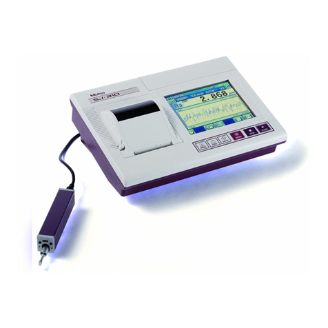
Mitutoyo SURFTEST SJ-410 User manual

SURFTEST
SJ-410
Surface Roughness
Tester
SJ-410
User’s Manual
Read this User’s Manual thoroughly before operating the
instrument. After reading, retain it close at hand for future reference.
No. 99MBB765A2
SERIES No. 178


No. 99MBB765A
i
CONVENTIONS USED IN THIS MANUAL
Safety Precautions
To ensure that instruments are operated correctly and safely, Mitutoyo manuals use
various safety symbols (Signal Words and Safety Alert Symbols) to identify and warn
against hazards and potential accidents.
The following symbols indicate general warnings:
DANGER
Indicates an imminently hazardous situation which, if not avoided, will result in serious
injury or death.
WARNING
Indicates a potentially hazardous situation which, if not avoided, could result in serious
injury or death.
CAUTION
Indicates a potentially hazardous situation which, if not avoided, may result in minor or
moderate injury or property damage.
The following safety signs indicate specific warnings or prohibited actions, or indicate a
mandatory action:
Alerts the user to a specific hazardous situation. The given example means “To warn
of electricity”.
Prohibits a specific action. The given example means “Do not touch”.
Specifies a mandatory action. The given example means “Connect an earth to the
ground”.

No. 99MBB765A
ii
CONVENTIONS USED IN THIS MANUAL
Types of Notes
The following types of notes are used in this manual to help the operator obtain reliable
measurement data through correct instrument operation.
IMPORTANT
An important note provides information essential to use the product. You cannot
disregard this note.
An important note is a type of precaution, which if neglected could result in degraded
performance or accuracy, or instrument malfunction/failure.
NOTE
A note provides information to be especially noted or supplemented to use the product.
A note also supplies information to be noted for specific operations (e.g., memory
limitation, instrument configuration, or details that apply to specific versions of a
program).
TIP
A tip is a type of note that helps the user to apply the operation method and procedures
to his or her specific conditions.
A tip also indicates the reference destination if there is information to be referred to.
•Mitutoyo assumes no liability to any party for any loss or damage, direct or
indirect, caused by use of this instrument not conforming to this manual.
•Information in this manual is subject to change without notice.
Copyright ©2011 Mitutoyo Corporation. All rights reserved.

No. 99MBB765A
iii
Electromagnetic Compatibility (EMC)
This product complies with the EMC Directive and the UK Electromagnetic Compatibility
Regulations; however, if this receives electromagnetic interference that exceeds these
requirements, it will be out of warranty and require appropriate measures.
This product is an industrial product, and is not intended to be used in residential
environment. If this product is used in residential environment, this product may cause
electromagnetic interference with other instruments. In such a case, it is required to take
appropriate measures for preventing such electromagnetic interference.
Precautions for Use
To obtain the highest performance from this instrument and to use it safely, read this
User's Manual prior to use.
This user's manual is intended for users of surface roughness testers SJ-410 standard
type, SJ-410 transverse tracing drive type, and SJ-410 detector retracting type.
"SJ-410" is used in almost all descriptions of this user's manual. If using model SJ-410
detector retracting type read this manual assuming "SJ-410" as "SJ-410 detector
retracting type". Unless otherwise noted, the manual gives common information about the
SJ-410 standard type and SJ-410 detector retracting type.
Observe the following precautions to get the most of the instrument and to attain high
accuracy for long time.
Caution
•This instrument has a sharp stylus at the edge of the detector. Take care not to be
injured.
IMPORTANT
•For the power supply, follow the conditions described on the AC adapter supplied. Do
not use other than the AC adapter provided.
•Do not disassemble the instrument unless otherwise specified in this User's Manual. It
will result in instrument failure or damage. The instrument has been rigorously adjusted
and assembled at the factory.
•Do not drop or give impact to the detector. The detector is a precision part.
•Do not use the instrument in an environment where it is subject to dust or vibrations.
Also keep it as far apart from noise generator such as large power supply, high-voltage
relay switch as possible.

No. 99MBB765A
iv
•Avoid using the instrument where there is sudden temperature change, and operate it
where the temperature is between 5 and 40 °C (RH: 85 % or less, free from dew
condensation). Do not operate/store the instrument close to a room heater or in the
direct sunlight.
•Store the instrument where the temperature can be controlled between -10 and 50 °C.
•When mounting the detector to the drive unit, take care not to apply excessive force to
the drive unit.
•Before connecting/detaching the connector or connecting cable, turn the power off (by
auto sleep function).
•The stylus tip is machined precisely. Take care not to break it.
•Before measurement, wipe off oil or dust on the work piece surface to be measured. For
supplying power to this system prepare an outlet rated to AC100V-240V ± 10%, 50/60
Hz. The supplied power should have a sufficient margin over the system consumption
rate.
•Do not place an object on the touch panel or give impact to the touch panel. Otherwise,
the touch panel may be damaged.
•Do not press the touch panel with a sharp-pointed object (such as a pen). Otherwise,
the touch panel may be damaged. To operate by the touch panel, use your finger or the
supplied touch pen.

No. 99MBB765A
v
Warranty
In the event that this product should prove defective in workmanship or material, within
one year from the date of original purchase for use, it will be repaired or replaced, at
Mitutoyo’s option, free of charge upon its prepaid return to Mitutoyo, without prejudice to
the provisions of the Mitutoyo Software End User License Agreement.
If this product fails or is damaged for any of the following reasons, it will be subject to a
repair charge, even if it is still under warranty.
(a) Failure or damage owing to fair wear and tear.
(b) Failure or damage owing to inappropriate handling, maintenance or repair, or to
unauthorized modification.
(c) Failure or damage owing to transport, dropping, or relocation of the instrument after
purchase.
(d) Failure or damage owing to fire, salt, gas, abnormal voltage, lightning surge, or
natural disaster.
(e) Failure or damage owing to use in combination with hardware or software other than
those designated or permitted by Mitutoyo.
(f) Failure or damage owing to use in ultra-hazardous activities.
This warranty is effective only where the instrument is properly installed and operated in
conformance with the instructions in this manual within the original country of the
installation.
EXCEPT AS SPECIFIED IN THIS WARRANTY, ALL EXPRESS OR IMPLIED
CONDITIONS, REPRESENTATIONS, AND WARRANTIES OF ANY NATURE
WHATSOEVER INCLUDING, WITHOUT LIMITATION, ANY IMPLIED WARRANTY OF
MERCHANTABILITY, FITNESS FOR A PARTICULAR PURPOSE, NONINFRINGEMENT
OR WARRANTY ARISING FROM A COURSE OF DEALING, USAGE, OR TRADE
PRACTICE, ARE HEREBY EXCLUDED TO THE MAXIMUM EXTENT ALLOWED BY
APPLICABLE LAW.
You assume all responsibility for all results arising out of its selection of this product to
achieve its intended results.

No. 99MBB765A
vi
Disclaimer
IN NO EVENT WILL MITUTOYO, ITS AFFILIATED AND RELATED COMPANIES AND
SUPPLIERS BE LIABLE FOR ANY LOST REVENUE, PROFIT, OR DATA, OR FOR
SPECIAL, DIRECT, INDIRECT, CONSEQUENTIAL, INCIDENTAL, OR PUNITIVE
DAMAGES HOWEVER CAUSED AND REGARDLESS OF THE THEORY OF LIABILITY
ARISING OUT OF THE USE OF OR INABILITY TO USE THIS PRODUCT EVEN IF
MITUTOYO OR ITS AFFILIATED AND RELATED COMPANIES AND/OR SUPPLIERS
HAVE BEEN ADVISED OF THE POSSIBILITY OF SUCH DAMAGES.
If, notwithstanding the foregoing, Mitutoyo is found to be liable to you for any damage or
loss which arises out of or is in any way connected with use of this product by you, in no
event shall Mitutoyo's and/or its affiliated and related companies’ and suppliers' liability to
you, whether in contract, tort (including negligence), or otherwise, exceed the price paid by
you for the product only.
The foregoing limitations shall apply even if the above-stated warranty fails of its essential
purpose.
BECAUSE SOME COUNTRIES, STATES OR JURISDICTIONS DO NOT ALLOW THE
EXCLUSION OR THE LIMITATION OF LIABILITY FOR CONSEQUENTIAL OR
INCIDENTAL DAMAGES, IN SUCH COUNTRIES, STATES OR JURISDICTIONS,
MITUTOYO'S LIABILITY SHALL BE LIMITED TO THE EXTENT PERMITTED BY LAW.
Export Control Compliance
This product falls into the Catch-All-Controlled Goods and/or Catch-All-Controlled
Technologies (including Programs) under Category 16 of Appended Table 1 of Export
Trade Control Order or under Category 16 of Appended Table of Foreign Exchange
Control Order, based on Foreign Exchange and Foreign Trade Act of Japan.
If you intend re-export of the product from a country other than Japan, re-sale of the
product in a country other than Japan, or re-providing of the technology (including
Programs), you shall observe the regulations of your country.
Also, if an option is added or modified to add a function to this product, this product may
fall under the category of List-Control Goods, List-Control Technology (including
Programs) under Category 1 - 15 of Appended Table 1 of Export Trade Control Order or
under Category 1 - 15 of Appended Table of Foreign Exchange Control Order, based on
Foreign Exchange and Foreign Trade Act of Japan. In that case, if you intend re-export of
the product from a country other than Japan, re-sale of the product in a country other than
Japan, or re-providing of the technology (including Programs), you shall observe the
regulations of your country. Please contact Mitutoyo in advance.

No. 99MBB765A
vii
Notes on Export to European Countries
When you intend exporting of this product to any of the European countries, it may be
required to provide User's Manual(s) in English and Declaration of Conformity in English
(in some cases, the official language of the country to be exported). For detailed
information, please contact Mitutoyo in advance.
Disposal of Products outside the European Countries
Please follow the official instruction in each community and country.
Disposal of Old Electrical & Electronic Equipment
(Applicable in the European Countries with separate
collection systems)
This symbol on the product or on its packaging is based on WEEE Directive (Directive on
Waste Electrical and Electronic Equipment), and this symbol indicates that this product
shall not be treated as household waste.
To reduce the environmental impact and minimize the volume of landfills, please
cooperate in reuse and recycle.
For how to dispose of the product, please contact your dealer or the nearest Mitutoyo
sales office.

No. 99MBB765A
viii
Disposal of Waste Batteries and Accumulators
(Applicable in the European Countries with Separate
Collection Systems)
EU
Hg
Batteries and accumulators containing heavy metals such as mercury, lead, and
cadmium may contaminate the environment if improperly discarded. When incinerated,
certain chemicals are released into the air or concentrated in the ash residue from the
combustion process; this may lead to a health risk to humans, animals and the
environment in general.
In compliance with legal requirements, the symbol of a 'crossed-out wheeled bin' is either
applied on the battery or on its packaging. This symbol indicates that disposal of the
batteries in household waste is strictly prohibited; instead the batteries have to be
disposed of by separate collection and recycling means. Additional marking identifies the
heavy metal content (i.e. Cd = cadmium, Hg = mercury, Pb = lead) as contained within
the battery if over prescribed levels.
End users are obliged by law to comply with the discarding procedure for waste
batteries. At Mitutoyo facilities, or at its appointed distributors, receptacles will be
provided to accept, at no charge, the disposal of previously supplied batteries.

No. 99MBB765A
ix
Contents
CONVENTIONS USED IN THIS MANUAL.........................................................................................................i
Electromagnetic Compatibility (EMC) ...........................................................................................................iii
Precautions for Use.........................................................................................................................................iii
Warranty ............................................................................................................................................................v
Disclaimer ........................................................................................................................................................vi
Export Control Compliance ............................................................................................................................vi
Notes on Export to European Countries......................................................................................................vii
Disposal of Products outside the European Countries..............................................................................vii
Disposal of Old Electrical & Electronic Equipment (Applicable in the European Countries with
Separate Collection Systems) .......................................................................................................................vii
Disposal of Waste Batteries and Accumulators (Applicable in the European Countries with Separate
Collection Systems) ......................................................................................................................................viii
Contents ...........................................................................................................................................................ix
1SJ-410 OVERVIEW ............................................................................................................................... 1-1
1.1 Outline of the SJ-410..................................................................................................................... 1-1
1.2 Standard SJ-410 Configuration ................................................................................................... 1-5
1.3 Name of Each Part on the SJ-410 ................................................................................................ 1-7
2OUTLINE OF THE SJ-410, FUNCTIONS AND KEY OPERATIONS.................................................... 2-1
2.1 Functions of Membrane Keys ...................................................................................................... 2-1
2.2 Outline of the Touch Panel ........................................................................................................... 2-3
2.2.1 Using the touch panel (Stylus pen) ..................................................................................... 2-3
2.2.2 Switching button display mode ........................................................................................... 2-4
2.2.3 Guidance screen.................................................................................................................... 2-4
2.2.4 Entering numeric values/characters.................................................................................... 2-5
2.3 Home Screen ................................................................................................................................. 2-8
2.4 Screen Hierarchy in the Display .................................................................................................2-11
2.5 List of Icons and Buttons ........................................................................................................... 2-26
3SETTING UP THE SJ-410 ..................................................................................................................... 3-1
3.1 SJ-410 Settings.............................................................................................................................. 3-1
3.2 Attaching a Stylus and a Nosepiece ........................................................................................... 3-2
3.2.1 Skidless measurement setup ............................................................................................... 3-3
3.2.2 Skid-attached measurement setup ...................................................................................... 3-4
3.3 Attaching and Detaching the Drive Unit and Detector .............................................................. 3-6
3.3.1 Attaching and detaching the detector ................................................................................. 3-6
3.3.2 Plugging/unplugging the connection cable...................................................................... 3-12

No. 99MBB765A
x
3.3.3 Checking the zero point: for skid-attached measurement setup....................................3-13
3.3.4 Adjusting the nosepiece height: for skid-attached measurement setup.......................3-15
3.4 Mounting and Dismounting the Height/Tilt Adjustment Unit ..................................................3-16
3.5 Attaching the Touch Panel Protection Sheet............................................................................3-17
3.6 Attaching the Touch Pen Strap ..................................................................................................3-18
3.7 Setting the Printer Paper ............................................................................................................3-19
3.8 Using the SD Card .......................................................................................................................3-21
3.8.1 Setting the SD card ..............................................................................................................3-22
3.8.2 Removing the SD card.........................................................................................................3-23
3.9 Power Supply ...............................................................................................................................3-24
3.9.1 Recharging the built-in battery...........................................................................................3-25
3.9.2 Turning on the power supply..............................................................................................3-27
3.9.3 Turning the power off ..........................................................................................................3-30
3.10 Initial Settings ..............................................................................................................................3-31
3.11 Attache Case ................................................................................................................................3-32
4MEASUREMENT FLOW........................................................................................................................4-1
4.1 Perform Measurement according to Overall Measurement Flow .............................................4-1
4.2 Perform Adjustment for Calibration and Measurement.............................................................4-2
4.2.1 Perform the vertical positioning...........................................................................................4-2
4.2.2 Perform the horizontal positioning ......................................................................................4-3
4.2.3 Perform zero adjustment.......................................................................................................4-3
4.2.4 Perform leveling .....................................................................................................................4-4
4.3 Perform Calibration .......................................................................................................................4-9
4.4 Modify the Condition Settings....................................................................................................4-10
4.5 Perform Measurement.................................................................................................................4-12
4.5.1 Set the workpiece and drive/detector unit. .......................................................................4-12
4.5.2 Start measurement ..............................................................................................................4-14
4.5.3 To start measurement from an arbitrary position.............................................................4-15
4.6 Switch the Display of Measurement Results ............................................................................4-17
4.6.1 Switch the parameter to be displayed ...............................................................................4-18
4.6.2 Display the evaluation profiles ...........................................................................................4-18
4.6.3 Display the graph .................................................................................................................4-19
4.6.4 Display the GO/NG judgment result...................................................................................4-19
4.6.5 Display the results at each sampling length.....................................................................4-20
4.7 Print the Measurement Results..................................................................................................4-21
4.8 To Use Various Optional Accessories .......................................................................................4-23
5OPERATION METHOD FOR THE DRIVE UNIT/DETECTOR /AUTOMATIC POSITIONING UNIT
(OPTIONAL ACCESSORIES).............................................................................................................5-1
5.1 Operation Method of the Drive Unit Screens Guide...................................................................5-1
5.2 Operation Method for the Drive Unit ...........................................................................................5-3
5.2.1 Repositioning the drive unit manually.................................................................................5-3
5.2.2 Repositioning the drive unit for narrow-area measurement .............................................5-3

No. 99MBB765A
xi
5.2.3 Returning ................................................................................................................................ 5-4
5.2.4 Auto-return ............................................................................................................................. 5-4
5.3 Shortening the Approach Length for Measurement .................................................................. 5-6
5.4 Operation Method for the Detector.............................................................................................. 5-8
5.4.1 Zero adjustment..................................................................................................................... 5-8
5.4.2 Zero-point shift ...................................................................................................................... 5-9
5.4.3 Switching the range..............................................................................................................5-11
5.5 Operation Method for the Automatic Positioning Unit (Optional Accessory)....................... 5-12
5.5.1 Outline of the automatic positioning unit ......................................................................... 5-12
5.5.2 Measurement using the automatic positioning unit ........................................................ 5-13
5.5.3 Moving the automatic positioning unit manually ............................................................. 5-15
6CALIBRATION ....................................................................................................................................... 6-1
6.1 Calibration Preparation................................................................................................................. 6-2
6.1.1 Calibration preparation ......................................................................................................... 6-2
6.2 Calibration Condition Setup Screens Guide .............................................................................. 6-5
6.3 Calibrating the SJ-410................................................................................................................... 6-8
6.4 Setting Calibration Conditions ...................................................................................................6-11
6.4.1 Setting the calibration method ........................................................................................... 6-12
6.4.2 Setting the number of measurements ............................................................................... 6-13
6.4.3 Changing the calibration conditions according to the precision roughness
specimen .............................................................................................................................. 6-14
6.4.4 Changing the calibration conditions according to the step specimen .......................... 6-16
6.5 Confirming the Calibration History ........................................................................................... 6-18
6.6 Setting the Stylus Alarm............................................................................................................. 6-19
6.7 Executing Preliminary Measurement for Calibration .............................................................. 6-21
6.8 Setting the Stylus Type ............................................................................................................... 6-21
7MODIFICATION OF THE MEASUREMENT CONDITIONS AND EVALUATING CONDITIONS ......... 7-1
7.1 Evaluating Conditions and Measurement Conditions............................................................... 7-2
7.2 Condition Setup Screens Guide .................................................................................................. 7-4
7.3 Setting Evaluating Conditions ..................................................................................................... 7-6
7.3.1 Modifying the roughness standard...................................................................................... 7-6
7.3.2 Modifying the evaluation profile and cut-off length ........................................................... 7-7
7.3.2.1 Modifying the evaluation profile ................................................................................... 7-7
7.3.2.2 Modifying the sampling length (L)/cut-off length (λs) of the unfiltered profile P..... 7-8
7.3.2.3 Modifying the cut-off length (λc, λs) of roughness profile R/DF ..............................7-11
7.3.2.4 Modifying cut-off length (λf, λc) of the waviness profile W...................................... 7-14
7.3.2.5 Modifying the upper limit length (A) of R-Motif ......................................................... 7-16
7.3.2.6 Modifying the upper limit lengths (A, B) of W-Motif.................................................. 7-19
7.3.3 Modifying the evaluation parameters ................................................................................ 7-22
7.3.4 Modifying profile filters ....................................................................................................... 7-23
7.3.5 Modifying the number of sampling lengths ...................................................................... 7-25
7.3.6 Setting the evaluation length to an arbitrary length ........................................................ 7-27
7.3.7 Setting pre-travel/post-travel.............................................................................................. 7-30

No. 99MBB765A
xii
7.3.8 Deleting unnecessary data .................................................................................................7-31
7.3.9 Setting the Language Display.............................................................................................7-36
7.3.10 Setting the mean line processing ......................................................................................7-47
7.4 Measurement Condition Setup Using Drawing Symbols ........................................................7-48
7.5 Setting Measurement Conditions ..............................................................................................7-49
7.5.1 Modifying the traversing speed..........................................................................................7-49
7.5.2 Setting the returning speed ................................................................................................7-50
7.5.3 Modifying the measuring range..........................................................................................7-51
7.5.4 Changing Over-Range Error Process Setting...................................................................7-52
7.5.5Setting the arm compensation ...........................................................................................7-53
7.5.6 Setting the auto-start function............................................................................................7-54
7.5.7 Setting the auto-return function .........................................................................................7-55
7.5.8 Setting the retraction ...........................................................................................................7-56
7.5.9 Setting X-axis operation......................................................................................................7-57
7.5.10 Setting the resume calculation...........................................................................................7-57
7.6 Simultaneous Evaluation of 2 Profiles (A/B) ............................................................................7-58
7.7 Measurement Recalculation .......................................................................................................7-61
7.8 Saving Measurement Conditions...............................................................................................7-62
8MODIFYING PARAMETERS .................................................................................................................8-1
8.1 Parameter Modification Screens Guide ......................................................................................8-1
8.2 Selecting the Displayed Parameters (Parameter Customization) ............................................8-3
8.2.1 Customizing parameters .......................................................................................................8-3
8.3 Parameter Detail Settings .............................................................................................................8-6
8.3.1 Setting calculation conditions when Sm, Pc, Ppi, or Rc are selected .............................8-6
8.3.2 Setting calculation conditions when HSC is selected .......................................................8-9
8.3.3 Setting calculation conditions when mr is selected ........................................................ 8-11
8.3.4 Setting calculation conditions when mr[c] (tp for ANSI) is selected..............................8-14
8.3.5 Setting calculation conditions when δc (Htp for ANSI) is selected ................................8-16
8.3.6 Calculation conditions when a profile motif (R-Motif/W-Motif) is selected ...................8-18
8.3.6.1 Setting a motif connection method.............................................................................8-18
8.3.6.2 Setting the W-Motif calculation condition ..................................................................8-19
8.3.7 Setting the GO/NG judgment function...............................................................................8-20
8.4 Modifying the Parameter Detail Settings from the Result Screen..........................................8-24
9CONDITION FILE...................................................................................................................................9-1
9.1 Condition File Screen Guide ........................................................................................................9-1
9.2 Operation using the Internal Memory..........................................................................................9-3
9.2.1 Loading the condition file .....................................................................................................9-3
9.2.2 Saving the condition file .......................................................................................................9-4
9.2.3 Deleting the condition file .....................................................................................................9-5
9.2.4 Renaming the condition file..................................................................................................9-6
9.3 Operation using the SD Card .......................................................................................................9-7
9.3.1 Loading the condition file .....................................................................................................9-7
9.3.1.1 Loading the condition file ..............................................................................................9-7

No. 99MBB765A
xiii
9.3.1.2 Searching the file to be loaded ..................................................................................... 9-8
9.3.2 Saving the condition file ....................................................................................................... 9-9
9.3.2.1 Saving the condition file newly ..................................................................................... 9-9
9.3.2.2 Overwriting the condition file .......................................................................................9-11
9.3.3 Deleting the condition file................................................................................................... 9-12
9.3.4 Renaming the condition file ............................................................................................... 9-13
10 MEASUREMENT RESULTS................................................................................................................ 10-1
10.1 Measurement Results Screen Guide......................................................................................... 10-2
10.2 Renaming a Folder on the SD Card ........................................................................................... 10-4
10.3 Loading Measurement Results from the SD Card ................................................................... 10-5
10.3.1Loading the saved measurement results.......................................................................... 10-5
10.3.2 Searching for files to load................................................................................................... 10-6
10.4 Saving Measurement Results to the SD Card .......................................................................... 10-8
10.4.1 Saving the measurement results newly ............................................................................ 10-8
10.4.2 Overwriting the measurement results ............................................................................. 10-10
10.4.3 Specifying the main folder................................................................................................ 10-12
10.5 Deleting the Measurement Results from the SD Card........................................................... 10-13
10.6 Renaming the Measurement Results on the SD Card ........................................................... 10-15
10.7 Loading the Save10-saved Data from the SD Card ............................................................... 10-17
11 CONFIRMING CALCULATION RESULTS BY LIST ............................................................................11-1
11.1 Checking the Results at Each Sampling Length ......................................................................11-2
12 STATISTICAL MEASUREMENT ......................................................................................................... 12-1
12.1 Outline of Statistical Measurement ........................................................................................... 12-1
12.2 Statistical Measurement Screen Guide..................................................................................... 12-2
12.3 Setting the Conditions for Statistical Measurement................................................................ 12-4
12.4 Executing the Statistical Measurement .................................................................................... 12-6
12.5 Confirming the Statistical Results............................................................................................. 12-7
12.6 Printing the Statistical Results .................................................................................................. 12-9
12.7 Loading the Statistical Data ..................................................................................................... 12-13
12.7.1 Loading the statistical data .............................................................................................. 12-13
12.7.2 Searching the file to be loaded ........................................................................................ 12-14
12.8 Saving the Statistical Data ....................................................................................................... 12-16
12.9 Deleting Statistical Data ........................................................................................................... 12-19
12.10 Renaming Statistical Data ........................................................................................................ 12-21
12.11 Performing Preliminary Measurement .................................................................................... 12-22
13 OPERATING ENVIRONMENT SETUP ............................................................................................... 13-1
13.1 Operating Environment Setup Screen Guide ........................................................................... 13-2
13.2 Printing the Environment Settings ............................................................................................ 13-4
13.3 Setting the Date and Time .......................................................................................................... 13-5
13.4 Data Output Settings................................................................................................................... 13-6

No. 99MBB765A
xiv
13.4.1 Setting the data output to SPC ...........................................................................................13-7
13.4.2 Setting data output to save data ........................................................................................13-8
13.4.3 Setting the data output to hard copy .................................................................................13-9
13.5 Print Setup..................................................................................................................................13-10
13.5.1 Setting the print items .......................................................................................................13-10
13.5.2 Setting the print magnification .........................................................................................13-15
13.6 Setting the Language Display ..................................................................................................13-19
13.7 Calibrating Drive Unit Speed ....................................................................................................13-20
13.8 Switching the Measurement Units ...........................................................................................13-22
13.9 Setting the Decimal Point .........................................................................................................13-23
13.10 Setting the Click Sound ............................................................................................................13-24
13.11 Restricting Operation Functions..............................................................................................13-25
13.12 SD Card Formatting and File Management.............................................................................13-27
13.12.1 SD card folder construction..............................................................................................13-28
13.12.2 Data saved on the SD card................................................................................................13-29
13.12.3 Formatting the SD card .....................................................................................................13-31
13.12.4 Checking the save status of the SD card ........................................................................13-32
13.12.5 Deleting data from the SD card ........................................................................................13-33
13.12.6 Saving text data to the SD card ........................................................................................13-35
13.12.7 Setting the Save10 function..............................................................................................13-36
13.12.8 Backing up to the SD card and restoring backup data ..................................................13-37
13.13 Timer Setting..............................................................................................................................13-40
13.13.1 Setting the auto-sleep function ........................................................................................13-40
13.13.2 Setting the self-timer .........................................................................................................13-41
13.13.3 Turning on ECO function ..................................................................................................13-42
13.14 Setting PC Communication Conditions ..................................................................................13-43
13.15 Displaying the Position of the Detector ..................................................................................13-45
13.16 Testing the Display and Membrane Keys................................................................................13-46
13.17 Calibrating the Touch Panel .....................................................................................................13-47
13.18 Selecting the Stylus ..................................................................................................................13-48
13.19 Selecting the Special Stylus.....................................................................................................13-50
13.20 Restoring Factory Default Settings .........................................................................................13-53
13.20.1 Items restored to original values when restoring factory default settings..................13-54
13.21 Checking the Version ................................................................................................................13-56
14 SWITCHING THE CALCULATION RESULTS SCREEN ....................................................................14-1
14.1 Screen Display .............................................................................................................................14-1
14.2 Switching the Calibration Results Screens Guide ...................................................................14-3
14.3 Switching Calculation Results screen ......................................................................................14-4
14.3.1 Switching the calculation results display screen.............................................................14-4
14.3.2 Trace display ........................................................................................................................14-5
14.4 Setting the Display of the Setting Conditions ..........................................................................14-7
14.5 Setting the Button Type ..............................................................................................................14-8
15 PRELIMINARY MEASUREMENT (AUXILIARY FUNCTIONS)...........................................................15-1

No. 99MBB765A
xv
15.1 Preliminary Measurement Screen Guide .................................................................................. 15-1
15.2 Modifying Preliminary Measurement Conditions .................................................................... 15-3
15.2.1 Modifying the measurement conditions............................................................................ 15-3
15.2.2 Modifying the measurement length ................................................................................... 15-4
15.2.3 Modifying the preliminary measurement conditions ....................................................... 15-5
15.3 Adjustment using the Tilt Knob ................................................................................................. 15-6
15.4 Adjustment using the Cross-travel Table ................................................................................. 15-9
15.5 Adjustment using the Leveling Table...................................................................................... 15-12
15.6 Adjustment using the XYZ Adjustment Table......................................................................... 15-16
15.7 Adjustment using the Tilt Adjustment Unit ............................................................................ 15-20
15.8 Detecting Peak/Bottom Position.............................................................................................. 15-23
16 DISPLAYING AND ANALYZING THE EVALUATION PROFILES AND GRAPHS............................. 16-1
16.1 Screen Guide of the Evaluation Profiles and Graphs.............................................................. 16-2
16.2 Displaying and Analyzing the Evaluation Profile ..................................................................... 16-4
16.2.1 Displaying the evaluation profile ....................................................................................... 16-4
16.2.2 Analyzing the coordinate difference.................................................................................. 16-7
16.2.3 Analyzing the step ..............................................................................................................16-11
16.2.4 Analyzing the step size ..................................................................................................... 16-17
16.2.5 Analyzing the step area..................................................................................................... 16-30
16.2.6 Setting the print magnification......................................................................................... 16-43
16.3 Analyzing the Graph ................................................................................................................. 16-44
16.3.1 Analyzing the BAC............................................................................................................. 16-44
16.3.2 Analyzing the ADC............................................................................................................. 16-48
17 USEFUL FEATURES OF THE SJ-410 ................................................................................................ 17-1
17.1 Guidance Screen ......................................................................................................................... 17-1
17.2 Measurement with the Short Approach Length ....................................................................... 17-2
17.3 Automatic Positioning Unit (Optional) ...................................................................................... 17-2
17.4 Indicating Contact State of the Detector................................................................................... 17-2
17.5 Displaying the Calculation Results Depending on Use .......................................................... 17-3
17.6 Saving/Loading the Conditions to/from the Internal Memory ................................................ 17-3
17.7 Saving Measurement Results Automatically............................................................................ 17-3
17.8 Hard Copying the Screen ........................................................................................................... 17-4
17.9 Automatic Printing after Completing Measurement ................................................................ 17-4
17.10 Stylus Alarm................................................................................................................................. 17-4
17.11 Function Restriction ................................................................................................................... 17-5
17.12 External Input Device.................................................................................................................. 17-5
17.13 Self-timer ...................................................................................................................................... 17-6
17.14 Inputting the Diagram Symbols ................................................................................................. 17-6
17.15 Printing Environment Setup....................................................................................................... 17-6
17.16 Backing up the Main Unit Information ...................................................................................... 17-6
17.17 Shortcut by using the Menu Key ............................................................................................... 17-7
17.18 Switching the Button Types ....................................................................................................... 17-7

No. 99MBB765A
xvi
18 SAVING AND OUTPUTTING MEASUREMENT RESULTS USING THE [DATA] KEY......................18-1
18.1 SPC Data Output..........................................................................................................................18-3
18.1.1 Selecting parameters...........................................................................................................18-4
18.1.2 Outputting SPC data............................................................................................................18-5
18.2 Saving Data to the SD Card ........................................................................................................18-6
18.2.1 Saving measurement results to the SD card ....................................................................18-6
18.2.2 Saving screen images to the SD card................................................................................18-7
19 INSTALLING THE SJ-410 WITH OPTIONAL ACCESSORIES ..........................................................19-1
19.1 Simple column stand ..................................................................................................................19-1
19.2 Optional Unit of the Simple Column Stand ...............................................................................19-3
19.2.1 Automatic positioning unit .................................................................................................19-3
19.2.2 Tilt adjustment unit ..............................................................................................................19-6
19.2.3 X-axis adjustment unit.........................................................................................................19-7
19.2.4 Attaching the units in combination....................................................................................19-9
19.3 Cross-travel Table......................................................................................................................19-21
19.4 Leveling Table ............................................................................................................................19-21
19.5 XYZ Adjustment Table...............................................................................................................19-22
20 MAINTENANCE AND INSPECTION OF THE SJ-410 ........................................................................20-1
20.1 Daily Care .....................................................................................................................................20-1
20.2 Replacing the Built-in Battery Pack...........................................................................................20-3
21 TROUBLESHOOTING .........................................................................................................................21-1
21.1 System Operation ........................................................................................................................21-1
21.2 Operation Error ............................................................................................................................21-3
21.3 Calculation Results .....................................................................................................................21-5
21.4 Outputting Measurement Results ..............................................................................................21-8
22 PRODUCT SPECIFICATIONS.............................................................................................................22-1
22.1 Detector ........................................................................................................................................22-1
22.2 Drive..............................................................................................................................................22-1
22.3Height/tilt adjustment unit ..........................................................................................................22-1
22.4 Display Unit ..................................................................................................................................22-2
22.4.1 Compatible roughness standard........................................................................................22-2
22.4.2 Condition settings ...............................................................................................................22-2
22.4.3 Cutoff lengths/sampling lengths, and sampling interval.................................................22-3
22.4.4 Motif maximum lengths and arbitrary length range .........................................................22-4
22.4.5 Parameters and roughness standards/evaluation profiles .............................................22-5
22.4.6 Measurement range and resolution ...................................................................................22-6
22.4.7 Traverse length ....................................................................................................................22-6
22.5 Power Supply ...............................................................................................................................22-7
22.6 Temperature/Humidity Range.....................................................................................................22-7
22.7 CE marking / UKCA marking ......................................................................................................22-7
22.8 External Dimensions and Mass..................................................................................................22-8

No. 99MBB765A
xvii
22.9 Optional Accessories................................................................................................................ 22-10
22.9.1 Optional accessories (except styli and nosepieces) ..................................................... 22-10
22.9.2 Styli and nosepiece ........................................................................................................... 22-12
22.9.3 Dimensions of stylus and nosepiece .............................................................................. 22-13
22.9.4 External dimensions of simple column stand ................................................................ 22-21
22.10 Consumables ............................................................................................................................. 22-22
22.11 SPC Output Specifications....................................................................................................... 22-22
22.12 Contact Connector Specifications .......................................................................................... 22-23
22.13 Connection Specifications with a Personal Computer ......................................................... 22-23
22.14 RS-232C Communication Specifications................................................................................ 22-24
23 REFERENCE INFORMATION ............................................................................................................. 23-1
23.1 Roughness Standard .................................................................................................................. 23-1
23.1.1 Evaluating based on JIS B0601-1982 ................................................................................ 23-1
23.1.2 Evaluation according to JIS B0601-1994........................................................................... 23-2
23.1.3 Evaluating based on VDA ................................................................................................... 23-3
23.1.4 Evaluation based on JIS B0601-2001 and ISO.................................................................. 23-4
23.1.5 Evaluating based on ANSI .................................................................................................. 23-5
23.2 Evaluation Profiles and Filters................................................................................................... 23-6
23.2.1 Evaluation profiles............................................................................................................... 23-6
23.2.2 Filters .................................................................................................................................... 23-9
23.2.3 Differences in filter characteristics.................................................................................. 23-12
23.2.4 Amplitude characteristics of 2CR and Gaussian filters ................................................ 23-13
23.3 Mean Line Compensation......................................................................................................... 23-14
23.4 Traverse Length......................................................................................................................... 23-15
23.5 Definitions of the SJ-410 Roughness Parameters ................................................................. 23-18
23.5.1 Ra (JIS1994, JIS2001, ISO1997, ANSI, VDA, Free): Arithmetic mean of roughness,
Ra (JIS1982): Arithmetic mean deviation of roughness ................................................ 23-18
23.5.2 Rq (JIS2001, ISO1997, ANSI, VDA, Free): Mean square of roughness......................... 23-18
23.5.3 Rz (JIS2001, ISO1997, ANSI, VDA, Free), Rmax (JIS1982), Ry (JIS1994, Free):
Maximum height ................................................................................................................ 23-19
23.5.4 Rp (JIS2001, ISO1997, ANSI, VDA, Free) Rpm (ANSI): Tallest peak ............................. 23-20
23.5.5 Rv (JIS2001, ISO1997, ANSI, VDA, Free): Maximum valley depth ................................ 23-20
23.5.6 Rt (JIS2001, ISO1997, ANSI, VDA, Free): Maximum roughness.................................... 23-20
23.5.7 R3z (Free): Third-level height ........................................................................................... 23-20
23.5.8 Rsk (JIS2001, ISO1997, ANSI, VDA, Free): Skewness (Degree of asymmetry) ........... 23-21
23.5.9 Rku (JIS2001, ISO1997, ANSI, VDA, Free): Kurtosis ...................................................... 23-22
23.5.10 Rc (JIS2001, ISO1997, ANSI, VDA, Free): Average height ............................................. 23-23
23.5.11 Pc (JIS1994), RPc (ANSI, ISO1997, Free): Peak count ................................................... 23-23
23.5.12 Sm (JIS1994), RSm (JIS2001, ISO1997, ANSI, VDA, Free):
Mountain and valley mean width ..................................................................................... 23-24
23.5.13 S (JIS1994, Free): Mean width of local peak ................................................................... 23-25
23.5.14 HSC (Free): High-spot count ............................................................................................ 23-26
23.5.15 Rmax (ANSI, VDA), Rz1max (ISO1997): Maximum height ............................................. 23-27

No. 99MBB765A
xviii
23.5.16 RzJIS (JIS2001, Free), Rz (JIS1982, 1994): 10-point mean roughness .........................23-27
23.5.17 Ppi (Free): Peak count .......................................................................................................23-28
23.5.18 Δa (ANSI, Free): Slope of the arithmetic mean (angle of the mean slope) ..................23-28
23.5.19 RΔq (ISO1997, JIS2001, ANSI, VDA, Free): Mean square slope (angle of the
mean square slope) ...........................................................................................................23-28
23.5.20 λa (Free): Arithmetic mean of wavelength.......................................................................23-28
23.5.21 λa (Free): Mean square slope ...........................................................................................23-28
23.5.22 Lo (Free): Developed profile length .................................................................................23-28
23.5.23 lr (Free): Expansion length ratio ......................................................................................23-29
23.5.24 mr (JIS2001, ISO1997, ANSI, VDA, Free): Material-ratio-length rate.............................23-29
23.5.25 mr[c] (ISO1997, JIS1994, 2001, VDA, Free), tp (ANSI): Material-ratio length rate........23-30
23.5.26 δc (JIS2001, ISO1997, VDA, Free), Htp (ANSI): Slice-level difference (plateau ratio) .23-31
23.5.27 tp (ANSI): Material-ratio length rate .................................................................................23-31
23.5.28 Htp (ANSI): Slice-level difference (plateau ratio) ............................................................23-31
23.5.29 Rk (JIS2001, ISO1997, VDA, Free): Enabled-material-ratio roughness (center
height) .................................................................................................................................23-32
23.5.30 Rpk (JIS2001, ISO1997, VDA, Free): Initial abrasion height (peak height)...................23-32
23.5.31 Rvk (JIS2001, ISO1997, VDA, Free): Valley depth...........................................................23-33
23.5.32 Mr1 (JIS2001, ISO1997, VDA, Free): Material-ratio length rate 1
(Upper relative-material-ratio length) ........................................................................23-33
23.5.33 Mr2 (JIS2001, ISO1997, VDA, Free): Material-ratio length rate 2
(Lower relative-material-ratio length)............................................................................23-34
23.5.34 A1 (JIS2001, ISO1997, VDA, Free): Peak area .................................................................23-34
23.5.35 A2 (JIS2001, ISO1997, VDA, Free): Valley area ...............................................................23-35
23.5.36 Vo (Free): Volume measure ...............................................................................................23-36
23.5.37 BAC: Material-ratio profile ................................................................................................23-37
23.5.38 ADC: Amplitude Distribution Curve .................................................................................23-38
23.6 Motif-related Parameters ..........................................................................................................23-39
23.6.1 How to obtain roughness motifs ......................................................................................23-39
23.6.2 Roughness motif parameters ...........................................................................................23-43
23.6.2.1 R (JIS2001, ISO1997, Free): Roughness motif mean depth ................................23-43
23.6.2.2 Rx (JIS2001, ISO1997, Free): Roughness motif maximum depth ......................23-43
23.6.2.3 AR (JIS2001, ISO1997, Free): Roughness motif average length ........................23-43
23.6.3 Obtaining waviness motifs ...............................................................................................23-43
23.6.4 Waviness motif parameters ..............................................................................................23-44
23.6.4.1 W (JIS2001, ISO1997): Waviness motif mean depth............................................23-44
23.6.4.2 Wx (JIS2001, ISO1997): Waviness motif maximum depth ..................................23-44
23.6.4.3 AW (JIS2001, ISO1997): Waviness motif mean length ........................................23-45
23.6.4.4 Wte (JIS2001, ISO1997): Total depth of waviness envelope curve ....................23-45
China RoHS Compliance Information
Service Network
Table of contents
Other Mitutoyo Test Equipment manuals
Popular Test Equipment manuals by other brands

I-Tech
I-Tech IT8600 Series Programming guide

phase II+
phase II+ DVM-1000 Operation manual

Fire-Eye
Fire-Eye HX Series manual

Unit
Unit UTD1000L Series user manual

Unit
Unit UT501B operating manual

Kyoritsu Electrical Instruments Works, Ltd.
Kyoritsu Electrical Instruments Works, Ltd. KEW4105DL instruction manual