atecpool SIROCCO AIHP115 User manual
ATECPOOL SIROCCO HEAT PUMP > User Manual
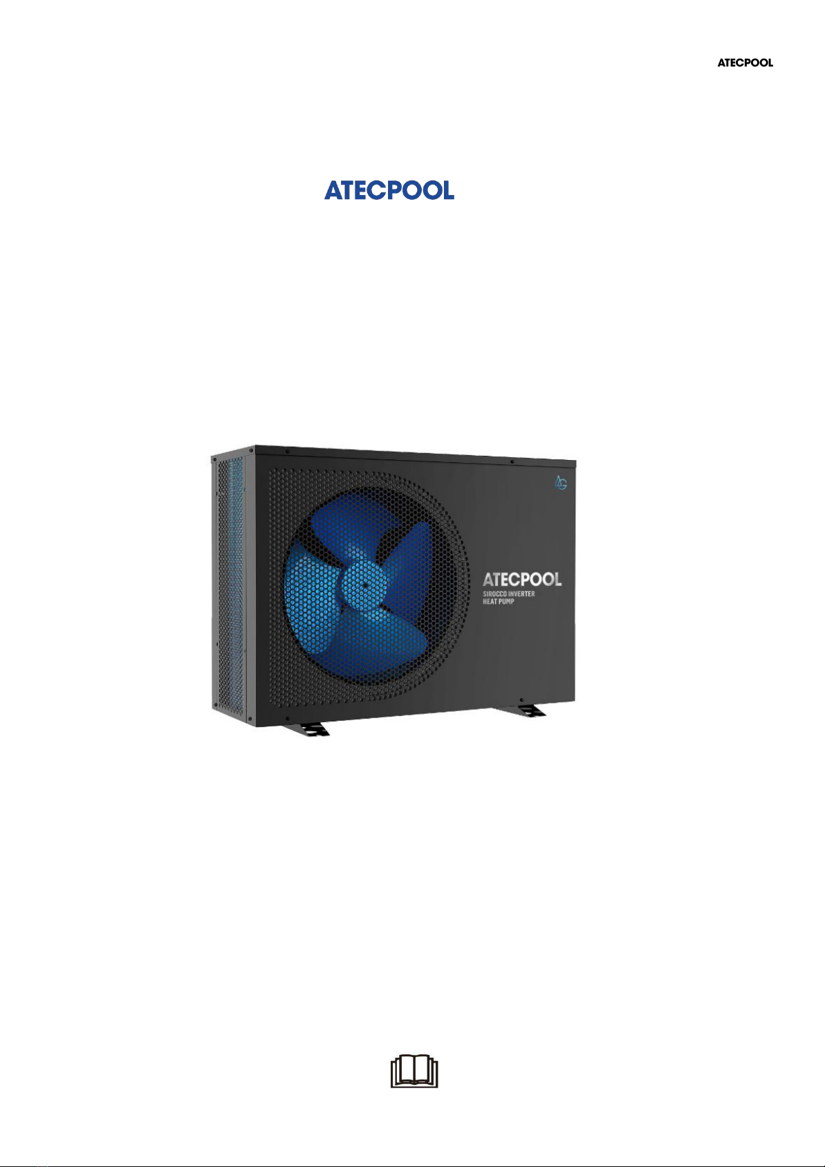
SIROCCO
INVERTER HEAT PUMP
Models: AIHP115 & AIHP180 & AIHP212& AIHP253
FULL DC INVERTER SWIMMING POOL HEAT PUMP
USER MANUAL
Please read this manual carefully before using and keep it in a safe place.

ATECPOOL SIROCCO HEAT PUMP > User Manual

ATECPOOL SIROCCO HEAT PUMP > User Manual
Contents
I. Unit Parameters 1
II. System Specification 2
1. Specification 2
2. Unit Dimensions 3
3. Exploded View 4
III. Installation Instructions 5
IV. Running Test 8
1. Inspection Before Running Test 8
2. Control Function Description 9
3. Fault Code and Solution 13
V. WIFI Settings 17

ATECPOOL SIROCCO HEAT PUMP > User Manual
1
I. Unit Parameters
1. Appearance
Please read the below instructions.
● Please install the unit in compliance with local laws, regulations and standards;
● Confirm power voltage and frequency;
● The unit should be installed by a professional installer
Warning
To be installed by professional installer only
⚠

ATECPOOL SIROCCO HEAT PUMP > User Manual
2
II. System Specification
1. Specification
Model
AIHP115
AIHP180
AIHP212
AIHP253
Ambient Temperature: (DB/WB) 27°C/24.3°C; Water Inlet/Outlet Temperature: 26°C/28°C.
Heating capacity (kW)
2.8~11.5
4.35~18.0
4.72~21.2
4.78~25.3
Power input (kW)
0.193~1.73
0.306~2.78
0.33~3.59
0.33~4.36
COP
14.5~6.65
14.2~6.47
14.3~5.91
14.48~5.8
Ambient Temperature: (DB/WB) 15°C/12°C; Water Inlet Temperature: 26°C.
Heating capacity (kW)
3.01~8.53
3.42~10.73
3.5- 14.2
3.8 - 17.1
Power input (kW)
0.393~1.592
0.453~2.167
0.47 - 2.88
0.49- 3.47
COP
7.65~5.36
7.55~4.95
7.45~4.93
7.76~4.93
Ambient Temperature: (DB/WB) 43°C/-; Water Inlet/Outlet Temperature: 30°C/28°C.
Cooling Capacity (kW)
2.04~5.75
2.83~8.3
3.0~9.6
3.6~10.65
Consumed Power (kW)
0.48~2.90
0.69~4.53
0.75~5.36
0.88~5.98
EER
4.25~1.98
4.08~1.83
4.01~1.79
4.09~1.78
Power supply
220-240V~ / 50-60Hz
380-415V/3N~/50-60Hz
Max.Input power(kW)
1.9
2.3
5.4
6.5
Max. current (A)
13.7
20.9
10.5
12.5
Heating temperature range
27°C~34°C
Cooling temperature range
26°C~15°C
Running temperature range
-10°C~48°C
Refrigerant
R410A
Compressor
MITSUBISHI ELECTRIC (DC inverter)
Air side heat exchanger
Hydrophilic fin exchanger
Water side heat exchanger
Titanium tube heat exchanger
Water flow (m³/h)
4.7
7.7
9.1
10.9
Net dimension LxWxH (mm)
980x399x660
1125x455x765
Water pipe
connection
Inlet/Outlet
(mm)
50
Net weight (kg)
44
52
75
85
Noise level dB(A)
54
55
58
59
The technical specification of our heat pumps is provided for information purpose only. We reserve the
right to make change without notice in advance.
1. Noise at 1m, 4m and 10m comply with Directives EN ISO 3741 and EN ISO 354.
2. Recommended size of heat pump is calculated for a covered pool.
This manual suits for next models
3
Table of contents
Popular Inverter manuals by other brands


BARRON
BARRON EXITRONIX Tucson Micro Series installation instructions

Baumer
Baumer HUBNER TDP 0,2 Series Mounting and operating instructions

electroil
electroil ITTPD11W-RS-BC Operation and Maintenance Handbook

Silicon Solar
Silicon Solar TPS555-1230 instruction manual

Mission Critical
Mission Critical Xantrex Freedom SW-RVC owner's guide

HP
HP 3312A Operating and service manual


