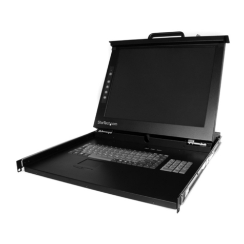
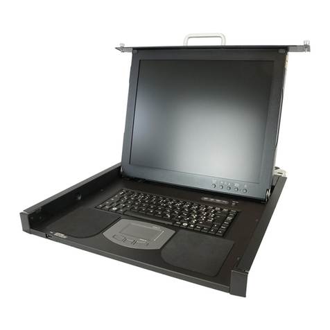
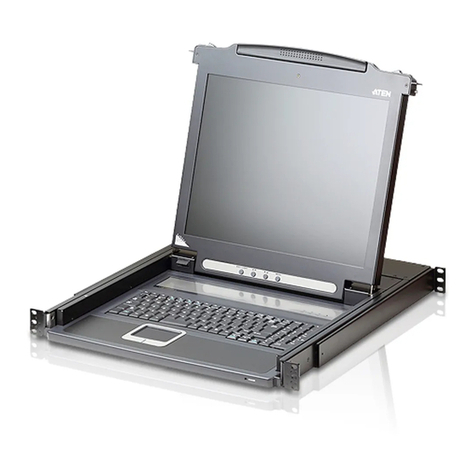
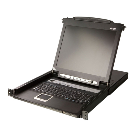
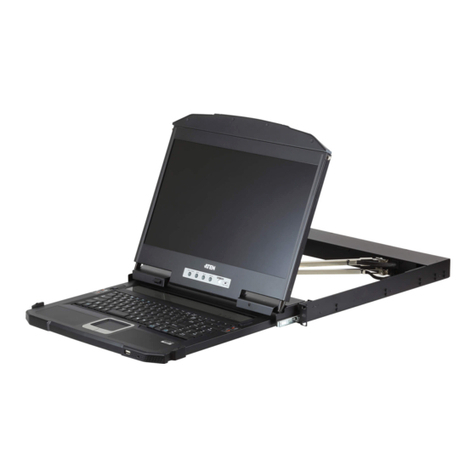
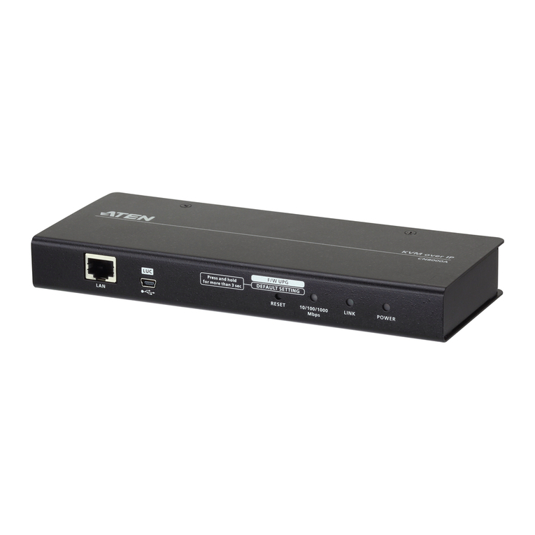
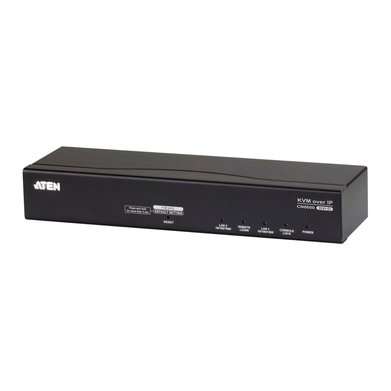
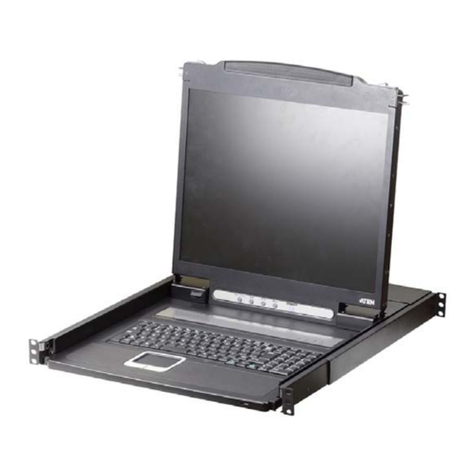
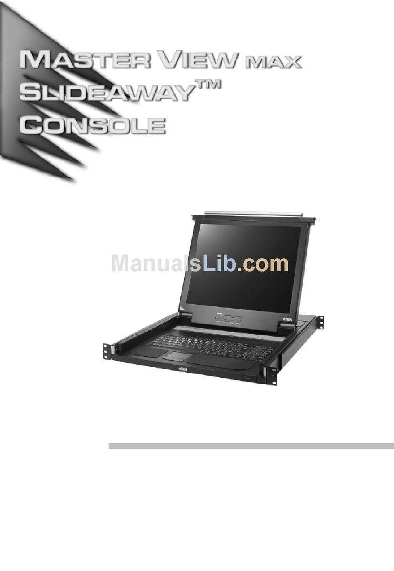
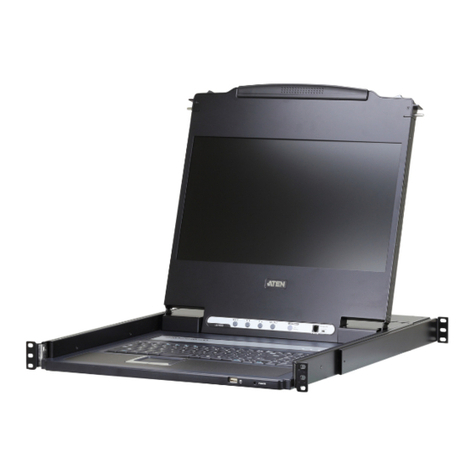
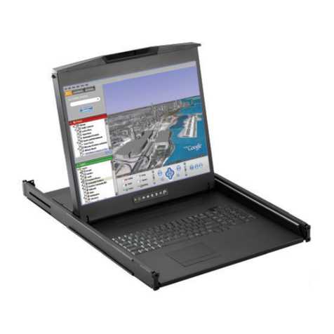
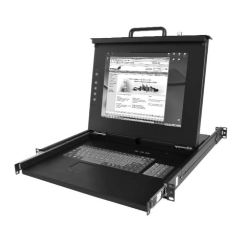
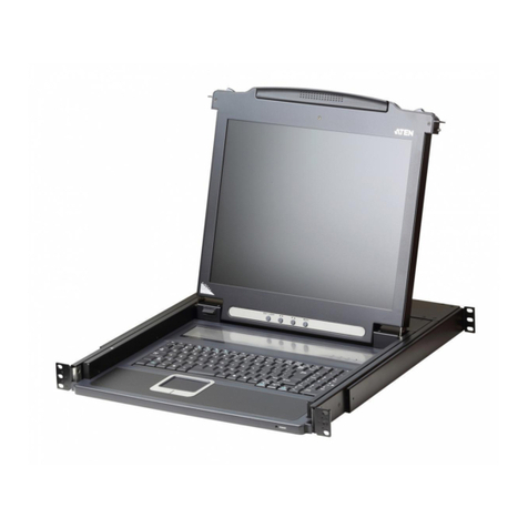
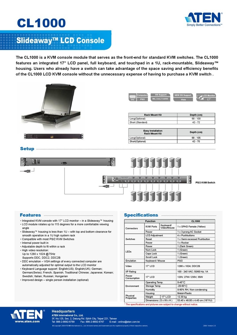
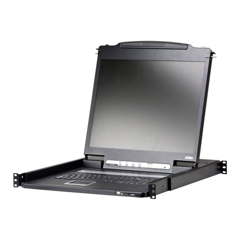
ATEN CL5800 User manual

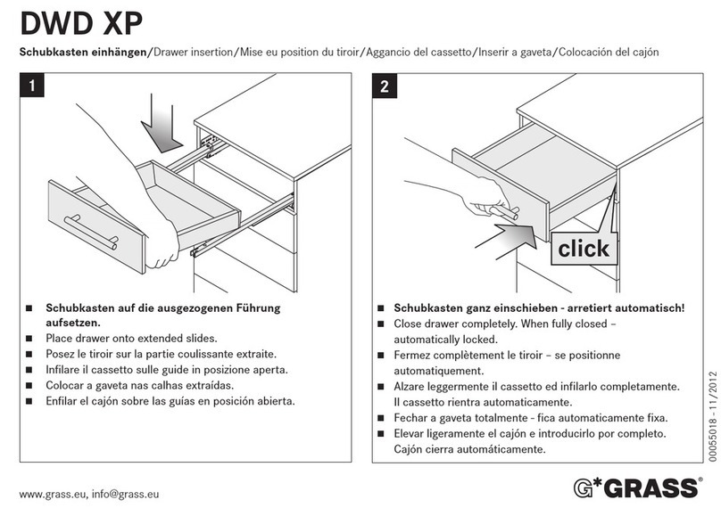
1
2
345
1
2
3
4
5
6
1
2
3
4
5
6
7
8
Press the Exit/Light pushbutton
for two seconds to turn the
LED light ON or Off. (Default: On)
EXIT ILIGHT
123 4
Package Contents
1 CL5800 Dual Rail LCD PS/2–USB
Console with Standard Rack Mount Kit
1 custom KVM cable
1 power cord
1 rmware upgrade cable
1 extension kit
1 user instructions
Support and Documentation Notice
All information, documentation, firmware,
software utilities, and specifications
contained in this package are subject to
change without prior notification by the
manufacturer.
To reduce the environmental impact of
our products, ATEN documentation and
software can be found online at
http://www.aten.com/download/
Technical Support
www.aten.com/support
Scan for more information
Product Page User Manual
Hardware Overview
Front View
Keyboard Module
LCD Module
Rear View
AInstallation
B
Standard Rack Mount
Dual Rail LCD Console
Quick Start Guide
CL5800
Operation
C
Opening the Console Closing the Console
Front-L Bracket Mount
CL5800
Power VGA
USB / PS/2
SPHD
2
5
1
4
6
3 3
Single Stage Installation
© Copyright 2023 ATEN®International Co. Ltd.
ATEN and the ATEN logo are registered trademarks of ATEN International Co., Ltd.
All rights reserved. All other trademarks are the property of their respective owners.
Part No. PAPE-1223-573G Released: 09/2023
Console LCD à double rail CL5800 www.aten.com
A
Description de l’appareil
Vue avant
1Poignée supérieure
2Module LCD
3Module clavier
4Poignée inférieure
5Voyant d’alimentation
6Loquet de libération LCD
7Supports de fi xation pour montage sur bâti
8Eclairage LED
Module clavier
1Loquet de libération du clavier
2Bouton de réinitialisation
3Voyants de verrouillage
4Clavier
5Pavé tactile
6Port USB
Module LCD
1Écran LCD
2Commandes LCD
3Bouton marche/arrêt de l'écran LCD
4Port de mise à jour du microprogramme
5Commutateur de mise à jour du
microprogramme
Vue arrière
1Prise d'alimentation
2Interrupteur
3Section de console externe
4Section des ports KVM
B
Installation
Montage en bâti standard
Un kit de montage sur bâti standard est fourni avec votre CL5800. Ce kit permet de
monter le commutateur sur un bâti, avec une profondeur de 52 à 85 cm.
Pour monter la console CL5800 sur bâti, procédez comme suit :
1. Alors que la première personne continue de maintenir en place la console CL5800,
la deuxième fait glisser les supports en L dans les supports de montage latéraux de la
CL5800 par l'arrière, jusqu'à ce que les brides des supports entrent en contact avec le
bâti, puis visse les supports en L sur le bâti.
2. Une fois les supports en L bien en place, serrez les vis des supports avant.
(En option) Support de montage avant en L
Pour assurer une posture à la fois confortable et sûre, installez les support avant en L qui
permettent d’avancer le rack vers l'avant et ainsi glisser l’unité davantage vers l'extérieur
et ainsi vous permettre d'incliner davantage l'écran LCD.
1. Fixez les supports de montage avant en L à l’avant du rack, en plaçant des vis dans les
languettes pour les maintenir en place.
Remarque : Les vis de rack ne sont pas fournies pour le montage de l’unité. Nous vous
recommandons d'utiliser deux vis M5 x P0,8 de chaque côté.
2. Demandez à une personne de positionner l'unité dans le rack et de la maintenir stable.
Demandez à la deuxième personne de visser les supports avant aux supports avant en L.
Remarque : Les vis de rack ne sont pas fournies pour le montage de l’unité. Nous vous
recommandons d'utiliser une vis M5 x P0,8 de chaque côté.
3. La deuxième personne doit, alors que la première personne maintient l'unité en place,
faire glisser les supports en L gauche et droit dans les supports de montage latéraux de
l'unité par l'arrière, en insérant quatre vis dans les supports pour les fixer en place.
4. Une fois les supports en L fixés, serrez toutes les vis. Assurez-vous de laisser un espace
d’au moins 5,1 cm de chaque côté pour permettre une ventilation adéquate et d’au
moins 12,7 cm à l’arrière pour le cordon d’alimentation et les câbles.
Installation en une étape
1Branchez une extrémité du connecteur SPHD du câble KVM sur le port KVM de la
console LCD.
2Branchez les connecteurs du clavier, du moniteur et de la souris du câble KVM sur les
ports correspondants de la section Console d'un commutateur KVM.
3Si vous installez une console externe, branchez votre clavier, votre moniteur et votre
souris sur leur port respectif sur la section Console de la console LCD. Les ports sont
identifi ables grâce un code de couleur et une icône spécifi que.
4Branchez le câble d'alimentation de la console CL5800 sur la prise d'alimentation de la
console LCD et sur une source d'alimentation.
5Allumez votre installation KVM.
6Allumez la console LCD.
C
Utilisation
Ouverture de la console
1. Tirez les loquets de libération pour dégager la console et tirez le panneau supérieur de
quelques centimètres vers vous.
2. En passant votre main en-dessous, tirez à fond le module clavier jusqu’à ce que vous
entendiez un clic indiquant qu’il est bien en place.
Fermeture de la console
1. Tirez vers vous les loquets de libération situés de chaque côté du clavier pour dégager
le module clavier puis faites légèrement glisser le module vers l’intérieur.
2. Tournez le module LCD complètement vers le bas puis tirez les loquets arrières pour
dégager le module LCD.
CL5800 Dual-Rail-LCD-Konsole www.aten.com
A
Hardwareübersicht
Vorderseitige Ansicht
1Griff oben
2LCD-Modul
3Tastaturmodul
4Griff unten
5LED-Betriebsanzeige
6Entriegelungstaste für LCD
7Arretierungen für Rack-Montage
8LED-Beleuchtung
Tastaturmodul
1Entriegelungstaste für Tastatur
2Reset-Taste
3Verriegelungs-LEDs
4Tastatur
5Touchpad
6USB-Port
LCD-Modul
1LCD-Display
2LCD-Bedienelemente
3Ein-/Ausschalter für LCD-Schirm
4Port zur Firmwareaktualisierung
5Schalter zur Firmwareaktualisierung
Rückseitige Ansicht
1Netzeingangsbuchse
2Netzschalter
3Externer Konsolabschnitt
4KVM-Portabschnitt
B
Installation
Standard-Rackmontage
Mit dem CL5800 wird ein Montagekit für ein Standard-Rack mitgeliefert. Mit diesem Kit
können Sie den Switch in ein Rack mit einer Tiefe von 52 -85 cm einbauen.
Um den CL5800 im Rack einzubauen, gehen Sie folgendermaßen vor:
1. Während die erste Person den CL5800 nach wie vor festhält, schiebt die zweite die
L-Schienen von hinten auf die seitlichen Montagerahmen des CL5800, bis der Flansch
den Rack berührt. Schrauben Sie die L-Schienen anschließend am Rack fest.
2. Nachdem Sie die L-Schienen befestigt haben, ziehen Sie auch die Schrauben an der
Vorderseite fest.
(Optional) Vordere L-Halterung
Um eine bequeme und sichere Körperhaltung einzunehmen, montieren Sie die vordere
L-Halterung, die eine Verlängerung an der Vorderseite des Gestells bietet, sodass das
Gerät weiter nach außen gleiten kann und Sie den LCD-Bildschirm somit weiter neigen
können.
1. Befestigen Sie die linke und rechte vordere L-Halterung an der Vorderseite des
Gestells, indem Sie die Schrauben in Halterungen einsetzen, um sie an Ort und Stelle
festzuschrauben.
Hinweis: Im Lieferumfang sind keine Gestellschrauben für die Montage der Einheit
erhalten. Wir empfehlen die Verwendung von zwei M5 x P0,8 Schrauben auf jeder
Seite.
2. Eine Person soll helfen, die Einheit am Gestell zu positionieren und zu fixieren. Lassen
Sie eine andere Person die vorderen Halterungen an die vordere L-Halterung schrauben.
Hinweis: Im Lieferumfang sind keine Gestellschrauben für die Montage der Einheit
erhalten. Wir empfehlen die Verwendung von einer M5 x P0,8 Schraube auf jeder Seite.
3. Während die erste Person die Einheit noch an Ort und Stelle hält, schiebt die zweite
Person die linken und rechten L-förmigen Halterungen von hinten in die seitlichen
Montagehalterungen der Einheit und schraubt die vier Schrauben in die Halterungen,
um sie zu sichern.
4. Nachdem die L-förmigen Halterungen befestigt sind, ziehen Sie alle Schrauben fest.
Lassen Sie für eine ordnungsgemäße Luftzirkulation an allen Seiten einen Freiraum
von mindestens 5,1 cm und mindestens 12,7 cm auf der Rückseite für die Netz- und
Anschlusskabel.
Einstufige Installation
1Verbinden Sie den SPHD-Stecker eines KVM-Kabels mit dem KVM-Port an der
LCD-Konsole.
2Verbinden Sie die Tastatur-, Monitor- und Mausanschlüsse des KVM-Kabels mit den
betreffenden Ports am Konsolabschnitt eines KVM-Switches.
3Wenn Sie eine externe Konsole anschließen möchten, verbinden Sie Tastatur, Monitor
und Maus mit den zugehörigen Anschlüssen im Konsolabschnitt der LCD-Konsole. Die
Buchsen sind farblich und mit einem Symbol gekennzeichnet.
4Verbinden Sie das Netzkabel des CL5800 mit der Stromeingangsbuchse der
LCD-Konsole und einer Stromquelle.
5Schalten Sie die KVM-Installation ein.
6Schalten Sie die LCD-Konsole ein.
C
Bedienung
Konsole öffnen
1. Ziehen Sie an den Griffen, um die Konsole zu entriegeln, und ziehen Sie das Gerät an
der Vorderseite einige Zentimeter zu sich heran.
2. Greifen Sie unter das Gerät, und ziehen Sie das Tastaturmodul ganz heraus, bis es
einrastet.
Konsole schließen
1. Ziehen Sie die Entriegelungsgriffe, die sich auf jeder Seite der Tastatur befi nden,
zu sich, um das Tastaturmodul freizugeben. Anschließend schieben Sie das Modul
vorsichtig hinein.
2. Klappen Sie das LCD-Modul ganz zu, und ziehen Sie an den rückseitigen Griffen, um es
zu entriegeln.
Consola LCD Dual Rail CL5800 www.aten.com
A
Reseña del hardware
Vista frontal
1Mango superior
2Módulo LCD
3Módulo de teclado
4Mango inferior
5Indicador LED de alimentación
6Botón de desbloqueo LCD
7Muescas para montaje en rack
8Iluminacion LED
Módulo de teclado
1Botón de desbloqueo del teclado
2Tecla de reseteo
3Indicadores LED de bloqueo
4Teclado
5Panel táctil
6Puerto USB
Módulo LCD
1Pantalla LCD
2Controles LCD
3Botón LCD encendido/apagado
4Puerto para actualizaciones del firmware
5Conmutador para actualizar el firmware
Vista posterior
1Entrada de alimentación
2Interruptor de alimentación
3Sección de consola externa
4Sección de puertos KVM
B
Instalación
Soporte para estantería estándar
Con el CL5800 viene un kit de montaje en rack estándar. Con este kit puede montarlo en
un rack con una profundidad entre 52 y 85 cm.
Para montar la CL5800 en el rack, haga lo siguiente:
1. Mientras la primera persona sigue aguantando la CL5800, la segunda desliza los raíles
en L sobre la CL5800 desde la parte trasera hasta que la pestaña del soporte haga
contacto con el rack y luego atornilla los raíles en L al rack.
2. Cuando tenga los raíles en L atornillados, apriete los tornillos frontales de los raíles.
(Opcional) Montaje de soporte en L delantero
Para disfrutar de una postura cómoda y segura, instale los soportes en L delanteros que
proporcionan una extensión en la parte delantera del bastidor, para hacer que la unidad se
pueda deslizar hacia fuera un poco más, permitiéndole inclinar la pantalla LCD aún más.
1. Acople los soportes en L delanteros izquierdo y derecho a la parte delantera de la
estantería, colocando tornillos en las pestañas para fijarlos en su posición.
Nota: No se suministran tornillos de estantería para montar la unidad. Recomendamos
que utilice dos tornillos M5 x P0,8 a cada lado.
2. Una persona debe colocar la unidad en la estantería y sujetarla de forma estable.
Otra segunda persona debe atornillar los soportes delanteros al soporte en L delantero.
Nota: No se suministran tornillos de estantería para montar la unidad. Recomendamos
que utilice un tornillo M5 x P0,8 a cada lado.
3. Mientras la primera persona mantiene la unidad en su lugar, la segunda persona
deslizará los soportes en forma de L izquierdo y derecho hacia los soportes de montaje
del lado de la unidad desde la parte posterior, instalando cuatro tornillos en los soportes
para fijarlos en su posición.
4. Después de haber fijado los soportes en forma de L, apriete todos los tornillos. Deje
al menos 5,1 cm a cada lado para una ventilación adecuada y al menos 12,7 cm en la
parte posterior para que el cable de alimentación se pueda mover holgadamente.
Instalación de una sola etapa
1Enchufe el conector SPHD de un cable KVM al puerto KVM de la consola LCD.
2Enchufe los conectores para teclado, monitor y ratón del cable KVM a los puertos
respectivos de la sección de consola de un conmutador KVM.
3Si instala una consola externa, enchufe el teclado, el monitor y el ratón a los puertos
respectivos de la sección de consola del equipo. Los puertos llevan el código de color
estándar, además de un icono para su identifi cación.
4Enchufe el cable de alimentación de la CL5800 a la entrada de alimentación de la
consola LCD y a una fuente de alimentación.
5Encienda toda la instalación KVM.
6Encienda la consola LCD.
C
Funcionamiento
Abrir la consola
1. Tire de los mangos de desbloqueo para liberar la consola y luego estire de la parte
anterior para acercar la unidad algunos centímetros hacia Usted.
2. Coloque la mano debajo del módulo de teclado y estírelo completamente hacia
adelante hasta que encaje y quede asegurado.
Cerrar la consola
1. Tire los mangos de desbloqueo ubicados en cada lado del teclado hacia Usted para
desbloquear el módulo de teclado y luego deslice el módulo cuidadosamente hacia
dentro.
2. Cierre el módulo LCD completamente y luego estire de los mangos posteriores para
desbloquear el módulo LCD.
Postazione CL5800 LCD a doppio binario www.aten.com
A
Panoramica hardware
Visione anteriore
1Maniglia superiore
2Modulo LCD
3Modulo tastiera
4Maniglia inferiore
5LED d’alimentazione
6Fermo di sganciamento del monitor LCD
7Linguette per il montaggio in rack
8Illuminazione LED
Modulo tastiera
1Fermo di sganciamento della tastiera
2Pulsante Ripristina
3LED di blocco
4Tastiera
5Tavoletta tattile
6Porta USB
Modulo LCD
1Display a cristalli liquidi
2Comandi LCD
3Pulsante di accensione/spegnimento
dello schermo
4Porta per l’aggiornamento del firmware
5Commutatore per l’aggiornamento del
firmware
Visione posteriore
1Presa per l’alimentazione
2Interruttore di alimentazione
3Sezione della console esterna
4Sezione della porta KVM
B
Installazione
Montaggio standard su rack
CL5800 è dotato di un kit standard per il montaggio in rack. Il kit consente di montare lo
switch in rack con una profondità di 52-85cm.
Per montare in rack il CL5800, procedere come segue:
1. Mentre la prima persona continua a tenere in posizione il CL5800, la seconda fa
scivolare le staffe a L nei supporti laterali di montaggio, partendo dal retro, fino a
quando non sono a stretto contatto con il rack e poi avvita le staffe a L al rack.
2. Una volta fissati i supporti a L, stringere le viti dei supporti anteriori.
(Opzionale) Montaggio della staffa anteriore a L
Per avere una postura comoda e corretta, installare le staffe anteriori a L che consentono
di estendere la parte anteriore del rack consentendo all’unità di scivolare ulteriormente e
consentendo di inclinare maggiormente lo schermo LCD.
1. Fissare le staffe anteriori a L, sia la destra che la sinistra, alla parte anteriore del rack,
inserendo delle viti nelle linguetteper fissarle correttamente.
Nota: Non vengono fornite le viti da rack per il montaggio di questa unità. Si consiglia
di utilizzare due viti M5 x P0,8 su ciascun lato.
2. Farsi aiutare da un’altra persona a posizionare l’unità nel rack e a tenerla ferma. La
seconda persona deve avvitare le staffe anteriori alla staffa a L anteriore.
Nota: Non vengono fornite le viti da rack per il montaggio di questa unità. Si consiglia
di utilizzare una vite M5 x P0,8 su ciascun lato.
3. Mentre una persona mantiene l’unità in posizione, la seconda persona fa scivolare
dal retro le staffe a L, sia la destra che la sinistra, nelle staffe di montaggio laterali
dell’unità, stringendo quattro viti nelle staffe per fissarle bene.
4. Dopo aver fissato le staffe a forma di L, stringere tutte le viti. Lasciare uno spazio di
almeno 5,1 cm su entrambi i lati per garantire un'adeguata areazione e uno spazio di
almeno 12,7 cm sul retro per contenere il cavo di alimentazione e lo spazio necessario
intorno.
Installazione a fase singola
1PCollegare l’estremità con il connettore SPHD di un cavo KVM alla porta KVM della
console LCD.
2Inserire i connettori della tastiera, del monitor e del mouse del cavo KVM nelle loro
rispettive porte sulla sezione della console dello switch KVM.
3In caso di installazione di una console esterna, collegare tastiera, mouse e monitor
nelle rispettive porte sulla sezione Console della console LCD. Le porte seguono un
codice a colori e sono contrassegnate da un’icona, per essere identificate facilmente.
4Inserire la spina del cavo dell’alimentazione del CL5800 nella presa dell’alimentazione
della console LCD e in una presa d’alimentazione di rete.
5Accendere l’installazione KVM.
6Accendere la Console LCD.
C
Funzionamento
Apertura della console
1. Per sganciare la console, sollevare i fermi di sganciamento e tirare a sé il pannello
superiore di pochi centimetri.
2. Raggiungere e tirare il modulo della tastiera fino a quando non scatta con un clic al suo
posto.
Chiusura della console
1. Per sganciare il modulo della tastiera, tirare a sé i fermi di sganciamento situati su ogni
lato della stessa e poi farlo scivolare leggermente verso l’interno.
2. Per sganciare il modulo LCD, ruotarlo il verso il basso e poi tirare i fermi di sganciamento
posteriori.
CL5800 Консоль Dual Rail с ЖК-дисплеем www.aten.com
А
Обзор оборудования
Вид спереди
1 Верхняя ручка
2 Модуль ЖК-дисплея
3 Клавиатурный модуль
4 Нижняя ручка
5 Индикатор питания
6 Фиксатор ЖК-дисплея
7 Кронштейны для монтажа в стойку
8 Светодиодная подсветка
Клавиатурный модуль
1 Фиксатор клавиатуры
2 Кнопка сброса настроек
3 Индикаторы блокировки
4 Клавиатура
5 Сенсорная панель
6 USB-разъем
Модуль ЖК-дисплея
1 ЖК-дисплей
2 Кнопки управления ЖК-дисплеем
3 Кнопка включения/отключения
ЖК-дисплея
4 Разъем для обновления прошивки
5 Переключатель обновления
прошивки
Вид сзади
1 Разъем питания
2 Выключатель питания
3 Секция внешней консоли
4 Блок KVM-портов
B
Установка
Стандартный монтаж в стойку
В комплектацию CL5800 входит стандартный набор для монтажа в стойку. С его
помощью переключатель можно установить в стойку глубиной 52–85 см.
Процедура монтажа CL5800 в стойку:
1. Зафиксируйте CL5800 в нужном положении силами одного человека. Поручите
второму задвинуть левый и правый Г-образные кронштейны в боковые посадочные
места на CL5800, действуя с задней стороны устройства. Когда Г-образные
кронштейны встанут вровень со стойкой, закрепите их с помощью винтов.
2. После крепления L-образных кронштейнов затяните винты передних кронштейнов.
(По выбору) Фронтальный монтаж Г-образных кронштейнов
Чтобы создать эргономичные и безопасные условия работы стоя или сидя,
установите фронтальные Г-образные кронштейны, которые удлиняют плечо в
передней части стойки. В результате устройство можно будет выдвинуть еще
дальше и наклонить ЖК-монитор под более удобным углом.
1. Закрепите левый и правый фронтальные Г-образные кронштейны на передней
части стойки, вставив крепежные винты в отверстия для фиксации.
Примечание. В комплектацию устройства не входят крепежные винты для
фиксации в стойке. Рекомендуем использовать с каждой стороны по два винта
M5 x P0,8.
2. Работу выполняют вдвоем. Один человек размещает устройство в стойке и крепко
удерживает его в этом положении. Второй привинчивает к передней части стойки
фронтальные Г-образные кронштейны.
Примечание. В комплектацию устройства не входят крепежные винты для
фиксации в стойке. Рекомендуем использовать с каждой стороны по одному
винту M5 x P0,8.
3. Зафиксируйте устройство в нужном положении силами одного человека.
Поручите второму задвинуть левый и правый Г-образные кронштейны в
боковые посадочные места на устройстве, действуя с его задней стороны.
Затем вставьте в эти кронштейны четыре винта для дальнейшей фиксации.
4. После фиксации Г-образных кронштейнов затяните все винты. Оставьте зазор
по меньшей мере 5,1 см с каждой стороны для надлежащей вентиляции и по
меньшей мере 12,7 см с задней стороны, чтобы уложить шнур питания и кабели.
Одноэтапная установка
1 Подключите кабель KVM к разъему KVM на консоли с ЖК-дисплеем так, чтобы
штекер SPHD вошел в консоль.
2 Подключите штекеры кабеля KVM, передающие сигнал на клавиатуру, мышь и
монитор, к соответствующим разъемам консольного блока KVM-переключателя.
3 В случае установки внешней консоли подключите клавиатуру, мышь и монитор
к соответствующим разъемам консольного блока на консоли с ЖК-дисплеем.
Разъемы легко различить благодаря цветовой кодировке и пиктограммам.
4 Подключите кабель питания CL5800 к разъему питания на консоли с ЖК-дисплеем
и к источнику питания.
5 Подайте питание на систему KVM в сборе.
6 Включите консоль с ЖК-дисплеем.
C
Эксплуатация
Открытие консоли
1. Потяните фиксаторы, чтобы освободить консоль, затем вытяните верхнюю
панель к себе на несколько сантиметров.
2. Нащупайте клавиатурный модуль под ней, затем вытяните его целиком до
щелчка, чтобы он встал на место.
Закрытие консоли
1. Потяните к себе фиксаторы по бокам клавиатуры, чтобы освободить
клавиатурный модуль, затем задвиньте его внутрь, не прилагая большого усилия.
2. Поверните модуль ЖК-дисплея вниз до упора, затем потяните задние
фиксаторы, чтобы освободить его.
CL5800 Dual Rail LCD Console www.aten.com
A
Hardware Overview
Front View
1upper handle
2LCD module
3keyboard module
4lower handle
5power LED
6LCD release catch
7rack mounting tabs
8LED illumination light
Keyboard Module
1keyboard release catch
2reset button
3lock LEDs
4keyboard
5touch pad
6USB port
LCD Module
1LCD display
2LCD controls
3LCD on / off button
4firmware upgrade port
5firmware upgrade switch
Rear View
1power socket
2power switch
3external console section
4KVM port section
B
Installation
Standard Rack Mount
A standard rack mount kit is provided with your CL5800. The kit enables the switch to be
mounted in rack with a depth of 52-85cm.
To rack mount the CL5800, do the following:
1. While the first person still holds the CL5800 in place, the second person slides the L
brackets into the CL5800's side mounting brackets from the rear until the bracket
flanges contact the rack, then screws the L brackets to the rack.
2. After the L brackets have been secured, tighten the front bracket screws.
(Optional) Front-L Bracket Mount
To have a comfortable and safe posture, install the Front-L brackets which provide an
extension at the front of the rack to help the unit slide further out and thus allowing you
to tilt the LCD screen more.
1. Attach the left and right Front-L brackets to the front of the rack, placing screws in the
tabs to secure them in place.
Note: Rack screws are not provided to mount the unit. We recommend that you use
two M5 x P0.8 screws on each side.
2. Have one person position the unit in the rack and hold it steady. Have the second
person screw the front brackets to the Front-L bracket.
Note: Rack screws are. not provided to mount the unit. We recommend that you use
one M5 x P0.8 screws on each side.
3. While the first person still holds the unit in place, the second person slides the left and
right L-shaped brackets into the unit’s side mounting brackets from the rear, installing
four screws in the brackets to secure them in place.
4. After the L-shaped brackets are secured, tighten all the screws. Allow at least 5.1 cm
on each side for proper ventilation, and at least 12.7 cm at the back for the power cord
and cable clearance.
Single Stage Installation
1Plug the SPHD connector end of a KVM cable into the LCD Console's KVM port.
2Plug the keyboard, monitor, and mouse connectors of the KVM cable into their
respective ports on the Console Section of a KVM switch.
3If you are installing an external console, plug your keyboard, monitor, and mouse into
their respective ports on the Console Section of the LCD Console. The ports are color
coded and marked with an icon for easy identification.
4Plug the CL5800’s power cord into the LCD Console's power socket and into a power
source.
5Power up your KVM installation.
6Turn on the power to LCD Console.
C
Operation
Opening the Console
1. Pull the release catches to release the console, and pull the top panel a few centimeters
toward you.
2. Reach underneath and pull the keyboard module all the way out until it clicks into
place.
Closing the Console
1. Pull the release catches located on either side of the keyboard toward you to release
the keyboard module, then slide the module slightly in.
2. Rotate the LCD module all the way down, then pull the rear catches to release the LCD
module.
1
2
345
1
2
3
4
5
6
1
2
3
4
5
6
7
8
Press the Exit/Light pushbutton
for two seconds to turn the
LED light ON or Off. (Default: On)
EXIT ILIGHT
123 4
Package Contents
1 CL5800 Dual Rail LCD PS/2–USB
Console with Standard Rack Mount Kit
1 custom KVM cable
1 power cord
1 rmware upgrade cable
1 extension kit
1 user instructions
Support and Documentation Notice
All information, documentation, firmware,
software utilities, and specifications
contained in this package are subject to
change without prior notification by the
manufacturer.
To reduce the environmental impact of
our products, ATEN documentation and
software can be found online at
http://www.aten.com/download/
Technical Support
www.aten.com/support
Scan for more information
Product Page User Manual
Hardware Overview
Front View
Keyboard Module
LCD Module
Rear View
AInstallation
B
Standard Rack Mount
Dual Rail LCD Console
Quick Start Guide
CL5800
Operation
C
Opening the Console Closing the Console
Front-L Bracket Mount
CL5800
Power VGA
USB / PS/2
SPHD
2
5
1
4
6
3 3
Single Stage Installation
© Copyright 2023 ATEN®International Co. Ltd.
ATEN and the ATEN logo are registered trademarks of ATEN International Co., Ltd.
All rights reserved. All other trademarks are the property of their respective owners.
Part No. PAPE-1223-573G Released: 09/2023
Console LCD à double rail CL5800 www.aten.com
A
Description de l’appareil
Vue avant
1Poignée supérieure
2Module LCD
3Module clavier
4Poignée inférieure
5Voyant d’alimentation
6Loquet de libération LCD
7Supports de fi xation pour montage sur bâti
8Eclairage LED
Module clavier
1Loquet de libération du clavier
2Bouton de réinitialisation
3Voyants de verrouillage
4Clavier
5Pavé tactile
6Port USB
Module LCD
1Écran LCD
2Commandes LCD
3Bouton marche/arrêt de l'écran LCD
4Port de mise à jour du microprogramme
5Commutateur de mise à jour du
microprogramme
Vue arrière
1Prise d'alimentation
2Interrupteur
3Section de console externe
4Section des ports KVM
B
Installation
Montage en bâti standard
Un kit de montage sur bâti standard est fourni avec votre CL5800. Ce kit permet de
monter le commutateur sur un bâti, avec une profondeur de 52 à 85 cm.
Pour monter la console CL5800 sur bâti, procédez comme suit :
1. Alors que la première personne continue de maintenir en place la console CL5800,
la deuxième fait glisser les supports en L dans les supports de montage latéraux de la
CL5800 par l'arrière, jusqu'à ce que les brides des supports entrent en contact avec le
bâti, puis visse les supports en L sur le bâti.
2. Une fois les supports en L bien en place, serrez les vis des supports avant.
(En option) Support de montage avant en L
Pour assurer une posture à la fois confortable et sûre, installez les support avant en L qui
permettent d’avancer le rack vers l'avant et ainsi glisser l’unité davantage vers l'extérieur
et ainsi vous permettre d'incliner davantage l'écran LCD.
1. Fixez les supports de montage avant en L à l’avant du rack, en plaçant des vis dans les
languettes pour les maintenir en place.
Remarque : Les vis de rack ne sont pas fournies pour le montage de l’unité. Nous vous
recommandons d'utiliser deux vis M5 x P0,8 de chaque côté.
2. Demandez à une personne de positionner l'unité dans le rack et de la maintenir stable.
Demandez à la deuxième personne de visser les supports avant aux supports avant en L.
Remarque : Les vis de rack ne sont pas fournies pour le montage de l’unité. Nous vous
recommandons d'utiliser une vis M5 x P0,8 de chaque côté.
3. La deuxième personne doit, alors que la première personne maintient l'unité en place,
faire glisser les supports en L gauche et droit dans les supports de montage latéraux de
l'unité par l'arrière, en insérant quatre vis dans les supports pour les fixer en place.
4. Une fois les supports en L fixés, serrez toutes les vis. Assurez-vous de laisser un espace
d’au moins 5,1 cm de chaque côté pour permettre une ventilation adéquate et d’au
moins 12,7 cm à l’arrière pour le cordon d’alimentation et les câbles.
Installation en une étape
1Branchez une extrémité du connecteur SPHD du câble KVM sur le port KVM de la
console LCD.
2Branchez les connecteurs du clavier, du moniteur et de la souris du câble KVM sur les
ports correspondants de la section Console d'un commutateur KVM.
3Si vous installez une console externe, branchez votre clavier, votre moniteur et votre
souris sur leur port respectif sur la section Console de la console LCD. Les ports sont
identifi ables grâce un code de couleur et une icône spécifi que.
4Branchez le câble d'alimentation de la console CL5800 sur la prise d'alimentation de la
console LCD et sur une source d'alimentation.
5Allumez votre installation KVM.
6Allumez la console LCD.
C
Utilisation
Ouverture de la console
1. Tirez les loquets de libération pour dégager la console et tirez le panneau supérieur de
quelques centimètres vers vous.
2. En passant votre main en-dessous, tirez à fond le module clavier jusqu’à ce que vous
entendiez un clic indiquant qu’il est bien en place.
Fermeture de la console
1. Tirez vers vous les loquets de libération situés de chaque côté du clavier pour dégager
le module clavier puis faites légèrement glisser le module vers l’intérieur.
2. Tournez le module LCD complètement vers le bas puis tirez les loquets arrières pour
dégager le module LCD.
CL5800 Dual-Rail-LCD-Konsole www.aten.com
A
Hardwareübersicht
Vorderseitige Ansicht
1Griff oben
2LCD-Modul
3Tastaturmodul
4Griff unten
5LED-Betriebsanzeige
6Entriegelungstaste für LCD
7Arretierungen für Rack-Montage
8LED-Beleuchtung
Tastaturmodul
1Entriegelungstaste für Tastatur
2Reset-Taste
3Verriegelungs-LEDs
4Tastatur
5Touchpad
6USB-Port
LCD-Modul
1LCD-Display
2LCD-Bedienelemente
3Ein-/Ausschalter für LCD-Schirm
4Port zur Firmwareaktualisierung
5Schalter zur Firmwareaktualisierung
Rückseitige Ansicht
1Netzeingangsbuchse
2Netzschalter
3Externer Konsolabschnitt
4KVM-Portabschnitt
B
Installation
Standard-Rackmontage
Mit dem CL5800 wird ein Montagekit für ein Standard-Rack mitgeliefert. Mit diesem Kit
können Sie den Switch in ein Rack mit einer Tiefe von 52 -85 cm einbauen.
Um den CL5800 im Rack einzubauen, gehen Sie folgendermaßen vor:
1. Während die erste Person den CL5800 nach wie vor festhält, schiebt die zweite die
L-Schienen von hinten auf die seitlichen Montagerahmen des CL5800, bis der Flansch
den Rack berührt. Schrauben Sie die L-Schienen anschließend am Rack fest.
2. Nachdem Sie die L-Schienen befestigt haben, ziehen Sie auch die Schrauben an der
Vorderseite fest.
(Optional) Vordere L-Halterung
Um eine bequeme und sichere Körperhaltung einzunehmen, montieren Sie die vordere
L-Halterung, die eine Verlängerung an der Vorderseite des Gestells bietet, sodass das
Gerät weiter nach außen gleiten kann und Sie den LCD-Bildschirm somit weiter neigen
können.
1. Befestigen Sie die linke und rechte vordere L-Halterung an der Vorderseite des
Gestells, indem Sie die Schrauben in Halterungen einsetzen, um sie an Ort und Stelle
festzuschrauben.
Hinweis: Im Lieferumfang sind keine Gestellschrauben für die Montage der Einheit
erhalten. Wir empfehlen die Verwendung von zwei M5 x P0,8 Schrauben auf jeder
Seite.
2. Eine Person soll helfen, die Einheit am Gestell zu positionieren und zu fixieren. Lassen
Sie eine andere Person die vorderen Halterungen an die vordere L-Halterung schrauben.
Hinweis: Im Lieferumfang sind keine Gestellschrauben für die Montage der Einheit
erhalten. Wir empfehlen die Verwendung von einer M5 x P0,8 Schraube auf jeder Seite.
3. Während die erste Person die Einheit noch an Ort und Stelle hält, schiebt die zweite
Person die linken und rechten L-förmigen Halterungen von hinten in die seitlichen
Montagehalterungen der Einheit und schraubt die vier Schrauben in die Halterungen,
um sie zu sichern.
4. Nachdem die L-förmigen Halterungen befestigt sind, ziehen Sie alle Schrauben fest.
Lassen Sie für eine ordnungsgemäße Luftzirkulation an allen Seiten einen Freiraum
von mindestens 5,1 cm und mindestens 12,7 cm auf der Rückseite für die Netz- und
Anschlusskabel.
Einstufige Installation
1Verbinden Sie den SPHD-Stecker eines KVM-Kabels mit dem KVM-Port an der
LCD-Konsole.
2Verbinden Sie die Tastatur-, Monitor- und Mausanschlüsse des KVM-Kabels mit den
betreffenden Ports am Konsolabschnitt eines KVM-Switches.
3Wenn Sie eine externe Konsole anschließen möchten, verbinden Sie Tastatur, Monitor
und Maus mit den zugehörigen Anschlüssen im Konsolabschnitt der LCD-Konsole. Die
Buchsen sind farblich und mit einem Symbol gekennzeichnet.
4Verbinden Sie das Netzkabel des CL5800 mit der Stromeingangsbuchse der
LCD-Konsole und einer Stromquelle.
5Schalten Sie die KVM-Installation ein.
6Schalten Sie die LCD-Konsole ein.
C
Bedienung
Konsole öffnen
1. Ziehen Sie an den Griffen, um die Konsole zu entriegeln, und ziehen Sie das Gerät an
der Vorderseite einige Zentimeter zu sich heran.
2. Greifen Sie unter das Gerät, und ziehen Sie das Tastaturmodul ganz heraus, bis es
einrastet.
Konsole schließen
1. Ziehen Sie die Entriegelungsgriffe, die sich auf jeder Seite der Tastatur befi nden,
zu sich, um das Tastaturmodul freizugeben. Anschließend schieben Sie das Modul
vorsichtig hinein.
2. Klappen Sie das LCD-Modul ganz zu, und ziehen Sie an den rückseitigen Griffen, um es
zu entriegeln.
Consola LCD Dual Rail CL5800 www.aten.com
A
Reseña del hardware
Vista frontal
1Mango superior
2Módulo LCD
3Módulo de teclado
4Mango inferior
5Indicador LED de alimentación
6Botón de desbloqueo LCD
7Muescas para montaje en rack
8Iluminacion LED
Módulo de teclado
1Botón de desbloqueo del teclado
2Tecla de reseteo
3Indicadores LED de bloqueo
4Teclado
5Panel táctil
6Puerto USB
Módulo LCD
1Pantalla LCD
2Controles LCD
3Botón LCD encendido/apagado
4Puerto para actualizaciones del firmware
5Conmutador para actualizar el firmware
Vista posterior
1Entrada de alimentación
2Interruptor de alimentación
3Sección de consola externa
4Sección de puertos KVM
B
Instalación
Soporte para estantería estándar
Con el CL5800 viene un kit de montaje en rack estándar. Con este kit puede montarlo en
un rack con una profundidad entre 52 y 85 cm.
Para montar la CL5800 en el rack, haga lo siguiente:
1. Mientras la primera persona sigue aguantando la CL5800, la segunda desliza los raíles
en L sobre la CL5800 desde la parte trasera hasta que la pestaña del soporte haga
contacto con el rack y luego atornilla los raíles en L al rack.
2. Cuando tenga los raíles en L atornillados, apriete los tornillos frontales de los raíles.
(Opcional) Montaje de soporte en L delantero
Para disfrutar de una postura cómoda y segura, instale los soportes en L delanteros que
proporcionan una extensión en la parte delantera del bastidor, para hacer que la unidad se
pueda deslizar hacia fuera un poco más, permitiéndole inclinar la pantalla LCD aún más.
1. Acople los soportes en L delanteros izquierdo y derecho a la parte delantera de la
estantería, colocando tornillos en las pestañas para fijarlos en su posición.
Nota: No se suministran tornillos de estantería para montar la unidad. Recomendamos
que utilice dos tornillos M5 x P0,8 a cada lado.
2. Una persona debe colocar la unidad en la estantería y sujetarla de forma estable.
Otra segunda persona debe atornillar los soportes delanteros al soporte en L delantero.
Nota: No se suministran tornillos de estantería para montar la unidad. Recomendamos
que utilice un tornillo M5 x P0,8 a cada lado.
3. Mientras la primera persona mantiene la unidad en su lugar, la segunda persona
deslizará los soportes en forma de L izquierdo y derecho hacia los soportes de montaje
del lado de la unidad desde la parte posterior, instalando cuatro tornillos en los soportes
para fijarlos en su posición.
4. Después de haber fijado los soportes en forma de L, apriete todos los tornillos. Deje
al menos 5,1 cm a cada lado para una ventilación adecuada y al menos 12,7 cm en la
parte posterior para que el cable de alimentación se pueda mover holgadamente.
Instalación de una sola etapa
1Enchufe el conector SPHD de un cable KVM al puerto KVM de la consola LCD.
2Enchufe los conectores para teclado, monitor y ratón del cable KVM a los puertos
respectivos de la sección de consola de un conmutador KVM.
3Si instala una consola externa, enchufe el teclado, el monitor y el ratón a los puertos
respectivos de la sección de consola del equipo. Los puertos llevan el código de color
estándar, además de un icono para su identifi cación.
4Enchufe el cable de alimentación de la CL5800 a la entrada de alimentación de la
consola LCD y a una fuente de alimentación.
5Encienda toda la instalación KVM.
6Encienda la consola LCD.
C
Funcionamiento
Abrir la consola
1. Tire de los mangos de desbloqueo para liberar la consola y luego estire de la parte
anterior para acercar la unidad algunos centímetros hacia Usted.
2. Coloque la mano debajo del módulo de teclado y estírelo completamente hacia
adelante hasta que encaje y quede asegurado.
Cerrar la consola
1. Tire los mangos de desbloqueo ubicados en cada lado del teclado hacia Usted para
desbloquear el módulo de teclado y luego deslice el módulo cuidadosamente hacia
dentro.
2. Cierre el módulo LCD completamente y luego estire de los mangos posteriores para
desbloquear el módulo LCD.
Postazione CL5800 LCD a doppio binario www.aten.com
A
Panoramica hardware
Visione anteriore
1Maniglia superiore
2Modulo LCD
3Modulo tastiera
4Maniglia inferiore
5LED d’alimentazione
6Fermo di sganciamento del monitor LCD
7Linguette per il montaggio in rack
8Illuminazione LED
Modulo tastiera
1Fermo di sganciamento della tastiera
2Pulsante Ripristina
3LED di blocco
4Tastiera
5Tavoletta tattile
6Porta USB
Modulo LCD
1Display a cristalli liquidi
2Comandi LCD
3Pulsante di accensione/spegnimento
dello schermo
4Porta per l’aggiornamento del firmware
5Commutatore per l’aggiornamento del
firmware
Visione posteriore
1Presa per l’alimentazione
2Interruttore di alimentazione
3Sezione della console esterna
4Sezione della porta KVM
B
Installazione
Montaggio standard su rack
CL5800 è dotato di un kit standard per il montaggio in rack. Il kit consente di montare lo
switch in rack con una profondità di 52-85cm.
Per montare in rack il CL5800, procedere come segue:
1. Mentre la prima persona continua a tenere in posizione il CL5800, la seconda fa
scivolare le staffe a L nei supporti laterali di montaggio, partendo dal retro, fino a
quando non sono a stretto contatto con il rack e poi avvita le staffe a L al rack.
2. Una volta fissati i supporti a L, stringere le viti dei supporti anteriori.
(Opzionale) Montaggio della staffa anteriore a L
Per avere una postura comoda e corretta, installare le staffe anteriori a L che consentono
di estendere la parte anteriore del rack consentendo all’unità di scivolare ulteriormente e
consentendo di inclinare maggiormente lo schermo LCD.
1. Fissare le staffe anteriori a L, sia la destra che la sinistra, alla parte anteriore del rack,
inserendo delle viti nelle linguetteper fissarle correttamente.
Nota: Non vengono fornite le viti da rack per il montaggio di questa unità. Si consiglia
di utilizzare due viti M5 x P0,8 su ciascun lato.
2. Farsi aiutare da un’altra persona a posizionare l’unità nel rack e a tenerla ferma. La
seconda persona deve avvitare le staffe anteriori alla staffa a L anteriore.
Nota: Non vengono fornite le viti da rack per il montaggio di questa unità. Si consiglia
di utilizzare una vite M5 x P0,8 su ciascun lato.
3. Mentre una persona mantiene l’unità in posizione, la seconda persona fa scivolare
dal retro le staffe a L, sia la destra che la sinistra, nelle staffe di montaggio laterali
dell’unità, stringendo quattro viti nelle staffe per fissarle bene.
4. Dopo aver fissato le staffe a forma di L, stringere tutte le viti. Lasciare uno spazio di
almeno 5,1 cm su entrambi i lati per garantire un'adeguata areazione e uno spazio di
almeno 12,7 cm sul retro per contenere il cavo di alimentazione e lo spazio necessario
intorno.
Installazione a fase singola
1PCollegare l’estremità con il connettore SPHD di un cavo KVM alla porta KVM della
console LCD.
2Inserire i connettori della tastiera, del monitor e del mouse del cavo KVM nelle loro
rispettive porte sulla sezione della console dello switch KVM.
3In caso di installazione di una console esterna, collegare tastiera, mouse e monitor
nelle rispettive porte sulla sezione Console della console LCD. Le porte seguono un
codice a colori e sono contrassegnate da un’icona, per essere identificate facilmente.
4Inserire la spina del cavo dell’alimentazione del CL5800 nella presa dell’alimentazione
della console LCD e in una presa d’alimentazione di rete.
5Accendere l’installazione KVM.
6Accendere la Console LCD.
C
Funzionamento
Apertura della console
1. Per sganciare la console, sollevare i fermi di sganciamento e tirare a sé il pannello
superiore di pochi centimetri.
2. Raggiungere e tirare il modulo della tastiera fino a quando non scatta con un clic al suo
posto.
Chiusura della console
1. Per sganciare il modulo della tastiera, tirare a sé i fermi di sganciamento situati su ogni
lato della stessa e poi farlo scivolare leggermente verso l’interno.
2. Per sganciare il modulo LCD, ruotarlo il verso il basso e poi tirare i fermi di sganciamento
posteriori.
CL5800 Консоль Dual Rail с ЖК-дисплеем www.aten.com
А
Обзор оборудования
Вид спереди
1 Верхняя ручка
2 Модуль ЖК-дисплея
3 Клавиатурный модуль
4 Нижняя ручка
5 Индикатор питания
6 Фиксатор ЖК-дисплея
7 Кронштейны для монтажа в стойку
8 Светодиодная подсветка
Клавиатурный модуль
1 Фиксатор клавиатуры
2 Кнопка сброса настроек
3 Индикаторы блокировки
4 Клавиатура
5 Сенсорная панель
6 USB-разъем
Модуль ЖК-дисплея
1 ЖК-дисплей
2 Кнопки управления ЖК-дисплеем
3 Кнопка включения/отключения
ЖК-дисплея
4 Разъем для обновления прошивки
5 Переключатель обновления
прошивки
Вид сзади
1 Разъем питания
2 Выключатель питания
3 Секция внешней консоли
4 Блок KVM-портов
B
Установка
Стандартный монтаж в стойку
В комплектацию CL5800 входит стандартный набор для монтажа в стойку. С его
помощью переключатель можно установить в стойку глубиной 52–85 см.
Процедура монтажа CL5800 в стойку:
1. Зафиксируйте CL5800 в нужном положении силами одного человека. Поручите
второму задвинуть левый и правый Г-образные кронштейны в боковые посадочные
места на CL5800, действуя с задней стороны устройства. Когда Г-образные
кронштейны встанут вровень со стойкой, закрепите их с помощью винтов.
2. После крепления L-образных кронштейнов затяните винты передних кронштейнов.
(По выбору) Фронтальный монтаж Г-образных кронштейнов
Чтобы создать эргономичные и безопасные условия работы стоя или сидя,
установите фронтальные Г-образные кронштейны, которые удлиняют плечо в
передней части стойки. В результате устройство можно будет выдвинуть еще
дальше и наклонить ЖК-монитор под более удобным углом.
1. Закрепите левый и правый фронтальные Г-образные кронштейны на передней
части стойки, вставив крепежные винты в отверстия для фиксации.
Примечание. В комплектацию устройства не входят крепежные винты для
фиксации в стойке. Рекомендуем использовать с каждой стороны по два винта
M5 x P0,8.
2. Работу выполняют вдвоем. Один человек размещает устройство в стойке и крепко
удерживает его в этом положении. Второй привинчивает к передней части стойки
фронтальные Г-образные кронштейны.
Примечание. В комплектацию устройства не входят крепежные винты для
фиксации в стойке. Рекомендуем использовать с каждой стороны по одному
винту M5 x P0,8.
3. Зафиксируйте устройство в нужном положении силами одного человека.
Поручите второму задвинуть левый и правый Г-образные кронштейны в
боковые посадочные места на устройстве, действуя с его задней стороны.
Затем вставьте в эти кронштейны четыре винта для дальнейшей фиксации.
4. После фиксации Г-образных кронштейнов затяните все винты. Оставьте зазор
по меньшей мере 5,1 см с каждой стороны для надлежащей вентиляции и по
меньшей мере 12,7 см с задней стороны, чтобы уложить шнур питания и кабели.
Одноэтапная установка
1 Подключите кабель KVM к разъему KVM на консоли с ЖК-дисплеем так, чтобы
штекер SPHD вошел в консоль.
2 Подключите штекеры кабеля KVM, передающие сигнал на клавиатуру, мышь и
монитор, к соответствующим разъемам консольного блока KVM-переключателя.
3 В случае установки внешней консоли подключите клавиатуру, мышь и монитор
к соответствующим разъемам консольного блока на консоли с ЖК-дисплеем.
Разъемы легко различить благодаря цветовой кодировке и пиктограммам.
4 Подключите кабель питания CL5800 к разъему питания на консоли с ЖК-дисплеем
и к источнику питания.
5 Подайте питание на систему KVM в сборе.
6 Включите консоль с ЖК-дисплеем.
C
Эксплуатация
Открытие консоли
1. Потяните фиксаторы, чтобы освободить консоль, затем вытяните верхнюю
панель к себе на несколько сантиметров.
2. Нащупайте клавиатурный модуль под ней, затем вытяните его целиком до
щелчка, чтобы он встал на место.
Закрытие консоли
1. Потяните к себе фиксаторы по бокам клавиатуры, чтобы освободить
клавиатурный модуль, затем задвиньте его внутрь, не прилагая большого усилия.
2. Поверните модуль ЖК-дисплея вниз до упора, затем потяните задние
фиксаторы, чтобы освободить его.
CL5800 Dual Rail LCD Console www.aten.com
A
Hardware Overview
Front View
1upper handle
2LCD module
3keyboard module
4lower handle
5power LED
6LCD release catch
7rack mounting tabs
8LED illumination light
Keyboard Module
1keyboard release catch
2reset button
3lock LEDs
4keyboard
5touch pad
6USB port
LCD Module
1LCD display
2LCD controls
3LCD on / off button
4firmware upgrade port
5firmware upgrade switch
Rear View
1power socket
2power switch
3external console section
4KVM port section
B
Installation
Standard Rack Mount
A standard rack mount kit is provided with your CL5800. The kit enables the switch to be
mounted in rack with a depth of 52-85cm.
To rack mount the CL5800, do the following:
1. While the first person still holds the CL5800 in place, the second person slides the L
brackets into the CL5800's side mounting brackets from the rear until the bracket
flanges contact the rack, then screws the L brackets to the rack.
2. After the L brackets have been secured, tighten the front bracket screws.
(Optional) Front-L Bracket Mount
To have a comfortable and safe posture, install the Front-L brackets which provide an
extension at the front of the rack to help the unit slide further out and thus allowing you
to tilt the LCD screen more.
1. Attach the left and right Front-L brackets to the front of the rack, placing screws in the
tabs to secure them in place.
Note: Rack screws are not provided to mount the unit. We recommend that you use
two M5 x P0.8 screws on each side.
2. Have one person position the unit in the rack and hold it steady. Have the second
person screw the front brackets to the Front-L bracket.
Note: Rack screws are. not provided to mount the unit. We recommend that you use
one M5 x P0.8 screws on each side.
3. While the first person still holds the unit in place, the second person slides the left and
right L-shaped brackets into the unit’s side mounting brackets from the rear, installing
four screws in the brackets to secure them in place.
4. After the L-shaped brackets are secured, tighten all the screws. Allow at least 5.1 cm
on each side for proper ventilation, and at least 12.7 cm at the back for the power cord
and cable clearance.
Single Stage Installation
1Plug the SPHD connector end of a KVM cable into the LCD Console's KVM port.
2Plug the keyboard, monitor, and mouse connectors of the KVM cable into their
respective ports on the Console Section of a KVM switch.
3If you are installing an external console, plug your keyboard, monitor, and mouse into
their respective ports on the Console Section of the LCD Console. The ports are color
coded and marked with an icon for easy identification.
4Plug the CL5800’s power cord into the LCD Console's power socket and into a power
source.
5Power up your KVM installation.
6Turn on the power to LCD Console.
C
Operation
Opening the Console
1. Pull the release catches to release the console, and pull the top panel a few centimeters
toward you.
2. Reach underneath and pull the keyboard module all the way out until it clicks into
place.
Closing the Console
1. Pull the release catches located on either side of the keyboard toward you to release
the keyboard module, then slide the module slightly in.
2. Rotate the LCD module all the way down, then pull the rear catches to release the LCD
module.
1
2
345
1
2
3
4
5
6
1
2
3
4
5
6
7
8
Press the Exit/Light pushbutton
for two seconds to turn the
LED light ON or Off. (Default: On)
EXIT ILIGHT
123 4
Package Contents
1 CL5800 Dual Rail LCD PS/2–USB
Console with Standard Rack Mount Kit
1 custom KVM cable
1 power cord
1 rmware upgrade cable
1 extension kit
1 user instructions
Support and Documentation Notice
All information, documentation, firmware,
software utilities, and specifications
contained in this package are subject to
change without prior notification by the
manufacturer.
To reduce the environmental impact of
our products, ATEN documentation and
software can be found online at
http://www.aten.com/download/
Technical Support
www.aten.com/support
Scan for more information
Product Page User Manual
Hardware Overview
Front View
Keyboard Module
LCD Module
Rear View
AInstallation
B
Standard Rack Mount
Dual Rail LCD Console
Quick Start Guide
CL5800
Operation
C
Opening the Console Closing the Console
Front-L Bracket Mount
CL5800
Power VGA
USB / PS/2
SPHD
2
5
1
4
6
3 3
Single Stage Installation
© Copyright 2023 ATEN®International Co. Ltd.
ATEN and the ATEN logo are registered trademarks of ATEN International Co., Ltd.
All rights reserved. All other trademarks are the property of their respective owners.
Part No. PAPE-1223-573G Released: 09/2023
Console LCD à double rail CL5800 www.aten.com
A
Description de l’appareil
Vue avant
1Poignée supérieure
2Module LCD
3Module clavier
4Poignée inférieure
5Voyant d’alimentation
6Loquet de libération LCD
7Supports de fi xation pour montage sur bâti
8Eclairage LED
Module clavier
1Loquet de libération du clavier
2Bouton de réinitialisation
3Voyants de verrouillage
4Clavier
5Pavé tactile
6Port USB
Module LCD
1Écran LCD
2Commandes LCD
3Bouton marche/arrêt de l'écran LCD
4Port de mise à jour du microprogramme
5Commutateur de mise à jour du
microprogramme
Vue arrière
1Prise d'alimentation
2Interrupteur
3Section de console externe
4Section des ports KVM
B
Installation
Montage en bâti standard
Un kit de montage sur bâti standard est fourni avec votre CL5800. Ce kit permet de
monter le commutateur sur un bâti, avec une profondeur de 52 à 85 cm.
Pour monter la console CL5800 sur bâti, procédez comme suit :
1. Alors que la première personne continue de maintenir en place la console CL5800,
la deuxième fait glisser les supports en L dans les supports de montage latéraux de la
CL5800 par l'arrière, jusqu'à ce que les brides des supports entrent en contact avec le
bâti, puis visse les supports en L sur le bâti.
2. Une fois les supports en L bien en place, serrez les vis des supports avant.
(En option) Support de montage avant en L
Pour assurer une posture à la fois confortable et sûre, installez les support avant en L qui
permettent d’avancer le rack vers l'avant et ainsi glisser l’unité davantage vers l'extérieur
et ainsi vous permettre d'incliner davantage l'écran LCD.
1. Fixez les supports de montage avant en L à l’avant du rack, en plaçant des vis dans les
languettes pour les maintenir en place.
Remarque : Les vis de rack ne sont pas fournies pour le montage de l’unité. Nous vous
recommandons d'utiliser deux vis M5 x P0,8 de chaque côté.
2. Demandez à une personne de positionner l'unité dans le rack et de la maintenir stable.
Demandez à la deuxième personne de visser les supports avant aux supports avant en L.
Remarque : Les vis de rack ne sont pas fournies pour le montage de l’unité. Nous vous
recommandons d'utiliser une vis M5 x P0,8 de chaque côté.
3. La deuxième personne doit, alors que la première personne maintient l'unité en place,
faire glisser les supports en L gauche et droit dans les supports de montage latéraux de
l'unité par l'arrière, en insérant quatre vis dans les supports pour les fixer en place.
4. Une fois les supports en L fixés, serrez toutes les vis. Assurez-vous de laisser un espace
d’au moins 5,1 cm de chaque côté pour permettre une ventilation adéquate et d’au
moins 12,7 cm à l’arrière pour le cordon d’alimentation et les câbles.
Installation en une étape
1Branchez une extrémité du connecteur SPHD du câble KVM sur le port KVM de la
console LCD.
2Branchez les connecteurs du clavier, du moniteur et de la souris du câble KVM sur les
ports correspondants de la section Console d'un commutateur KVM.
3Si vous installez une console externe, branchez votre clavier, votre moniteur et votre
souris sur leur port respectif sur la section Console de la console LCD. Les ports sont
identifi ables grâce un code de couleur et une icône spécifi que.
4Branchez le câble d'alimentation de la console CL5800 sur la prise d'alimentation de la
console LCD et sur une source d'alimentation.
5Allumez votre installation KVM.
6Allumez la console LCD.
C
Utilisation
Ouverture de la console
1. Tirez les loquets de libération pour dégager la console et tirez le panneau supérieur de
quelques centimètres vers vous.
2. En passant votre main en-dessous, tirez à fond le module clavier jusqu’à ce que vous
entendiez un clic indiquant qu’il est bien en place.
Fermeture de la console
1. Tirez vers vous les loquets de libération situés de chaque côté du clavier pour dégager
le module clavier puis faites légèrement glisser le module vers l’intérieur.
2. Tournez le module LCD complètement vers le bas puis tirez les loquets arrières pour
dégager le module LCD.
CL5800 Dual-Rail-LCD-Konsole www.aten.com
A
Hardwareübersicht
Vorderseitige Ansicht
1Griff oben
2LCD-Modul
3Tastaturmodul
4Griff unten
5LED-Betriebsanzeige
6Entriegelungstaste für LCD
7Arretierungen für Rack-Montage
8LED-Beleuchtung
Tastaturmodul
1Entriegelungstaste für Tastatur
2Reset-Taste
3Verriegelungs-LEDs
4Tastatur
5Touchpad
6USB-Port
LCD-Modul
1LCD-Display
2LCD-Bedienelemente
3Ein-/Ausschalter für LCD-Schirm
4Port zur Firmwareaktualisierung
5Schalter zur Firmwareaktualisierung
Rückseitige Ansicht
1Netzeingangsbuchse
2Netzschalter
3Externer Konsolabschnitt
4KVM-Portabschnitt
B
Installation
Standard-Rackmontage
Mit dem CL5800 wird ein Montagekit für ein Standard-Rack mitgeliefert. Mit diesem Kit
können Sie den Switch in ein Rack mit einer Tiefe von 52 -85 cm einbauen.
Um den CL5800 im Rack einzubauen, gehen Sie folgendermaßen vor:
1. Während die erste Person den CL5800 nach wie vor festhält, schiebt die zweite die
L-Schienen von hinten auf die seitlichen Montagerahmen des CL5800, bis der Flansch
den Rack berührt. Schrauben Sie die L-Schienen anschließend am Rack fest.
2. Nachdem Sie die L-Schienen befestigt haben, ziehen Sie auch die Schrauben an der
Vorderseite fest.
(Optional) Vordere L-Halterung
Um eine bequeme und sichere Körperhaltung einzunehmen, montieren Sie die vordere
L-Halterung, die eine Verlängerung an der Vorderseite des Gestells bietet, sodass das
Gerät weiter nach außen gleiten kann und Sie den LCD-Bildschirm somit weiter neigen
können.
1. Befestigen Sie die linke und rechte vordere L-Halterung an der Vorderseite des
Gestells, indem Sie die Schrauben in Halterungen einsetzen, um sie an Ort und Stelle
festzuschrauben.
Hinweis: Im Lieferumfang sind keine Gestellschrauben für die Montage der Einheit
erhalten. Wir empfehlen die Verwendung von zwei M5 x P0,8 Schrauben auf jeder
Seite.
2. Eine Person soll helfen, die Einheit am Gestell zu positionieren und zu fixieren. Lassen
Sie eine andere Person die vorderen Halterungen an die vordere L-Halterung schrauben.
Hinweis: Im Lieferumfang sind keine Gestellschrauben für die Montage der Einheit
erhalten. Wir empfehlen die Verwendung von einer M5 x P0,8 Schraube auf jeder Seite.
3. Während die erste Person die Einheit noch an Ort und Stelle hält, schiebt die zweite
Person die linken und rechten L-förmigen Halterungen von hinten in die seitlichen
Montagehalterungen der Einheit und schraubt die vier Schrauben in die Halterungen,
um sie zu sichern.
4. Nachdem die L-förmigen Halterungen befestigt sind, ziehen Sie alle Schrauben fest.
Lassen Sie für eine ordnungsgemäße Luftzirkulation an allen Seiten einen Freiraum
von mindestens 5,1 cm und mindestens 12,7 cm auf der Rückseite für die Netz- und
Anschlusskabel.
Einstufige Installation
1Verbinden Sie den SPHD-Stecker eines KVM-Kabels mit dem KVM-Port an der
LCD-Konsole.
2Verbinden Sie die Tastatur-, Monitor- und Mausanschlüsse des KVM-Kabels mit den
betreffenden Ports am Konsolabschnitt eines KVM-Switches.
3Wenn Sie eine externe Konsole anschließen möchten, verbinden Sie Tastatur, Monitor
und Maus mit den zugehörigen Anschlüssen im Konsolabschnitt der LCD-Konsole. Die
Buchsen sind farblich und mit einem Symbol gekennzeichnet.
4Verbinden Sie das Netzkabel des CL5800 mit der Stromeingangsbuchse der
LCD-Konsole und einer Stromquelle.
5Schalten Sie die KVM-Installation ein.
6Schalten Sie die LCD-Konsole ein.
C
Bedienung
Konsole öffnen
1. Ziehen Sie an den Griffen, um die Konsole zu entriegeln, und ziehen Sie das Gerät an
der Vorderseite einige Zentimeter zu sich heran.
2. Greifen Sie unter das Gerät, und ziehen Sie das Tastaturmodul ganz heraus, bis es
einrastet.
Konsole schließen
1. Ziehen Sie die Entriegelungsgriffe, die sich auf jeder Seite der Tastatur befi nden,
zu sich, um das Tastaturmodul freizugeben. Anschließend schieben Sie das Modul
vorsichtig hinein.
2. Klappen Sie das LCD-Modul ganz zu, und ziehen Sie an den rückseitigen Griffen, um es
zu entriegeln.
Consola LCD Dual Rail CL5800 www.aten.com
A
Reseña del hardware
Vista frontal
1Mango superior
2Módulo LCD
3Módulo de teclado
4Mango inferior
5Indicador LED de alimentación
6Botón de desbloqueo LCD
7Muescas para montaje en rack
8Iluminacion LED
Módulo de teclado
1Botón de desbloqueo del teclado
2Tecla de reseteo
3Indicadores LED de bloqueo
4Teclado
5Panel táctil
6Puerto USB
Módulo LCD
1Pantalla LCD
2Controles LCD
3Botón LCD encendido/apagado
4Puerto para actualizaciones del firmware
5Conmutador para actualizar el firmware
Vista posterior
1Entrada de alimentación
2Interruptor de alimentación
3Sección de consola externa
4Sección de puertos KVM
B
Instalación
Soporte para estantería estándar
Con el CL5800 viene un kit de montaje en rack estándar. Con este kit puede montarlo en
un rack con una profundidad entre 52 y 85 cm.
Para montar la CL5800 en el rack, haga lo siguiente:
1. Mientras la primera persona sigue aguantando la CL5800, la segunda desliza los raíles
en L sobre la CL5800 desde la parte trasera hasta que la pestaña del soporte haga
contacto con el rack y luego atornilla los raíles en L al rack.
2. Cuando tenga los raíles en L atornillados, apriete los tornillos frontales de los raíles.
(Opcional) Montaje de soporte en L delantero
Para disfrutar de una postura cómoda y segura, instale los soportes en L delanteros que
proporcionan una extensión en la parte delantera del bastidor, para hacer que la unidad se
pueda deslizar hacia fuera un poco más, permitiéndole inclinar la pantalla LCD aún más.
1. Acople los soportes en L delanteros izquierdo y derecho a la parte delantera de la
estantería, colocando tornillos en las pestañas para fijarlos en su posición.
Nota: No se suministran tornillos de estantería para montar la unidad. Recomendamos
que utilice dos tornillos M5 x P0,8 a cada lado.
2. Una persona debe colocar la unidad en la estantería y sujetarla de forma estable.
Otra segunda persona debe atornillar los soportes delanteros al soporte en L delantero.
Nota: No se suministran tornillos de estantería para montar la unidad. Recomendamos
que utilice un tornillo M5 x P0,8 a cada lado.
3. Mientras la primera persona mantiene la unidad en su lugar, la segunda persona
deslizará los soportes en forma de L izquierdo y derecho hacia los soportes de montaje
del lado de la unidad desde la parte posterior, instalando cuatro tornillos en los soportes
para fijarlos en su posición.
4. Después de haber fijado los soportes en forma de L, apriete todos los tornillos. Deje
al menos 5,1 cm a cada lado para una ventilación adecuada y al menos 12,7 cm en la
parte posterior para que el cable de alimentación se pueda mover holgadamente.
Instalación de una sola etapa
1Enchufe el conector SPHD de un cable KVM al puerto KVM de la consola LCD.
2Enchufe los conectores para teclado, monitor y ratón del cable KVM a los puertos
respectivos de la sección de consola de un conmutador KVM.
3Si instala una consola externa, enchufe el teclado, el monitor y el ratón a los puertos
respectivos de la sección de consola del equipo. Los puertos llevan el código de color
estándar, además de un icono para su identifi cación.
4Enchufe el cable de alimentación de la CL5800 a la entrada de alimentación de la
consola LCD y a una fuente de alimentación.
5Encienda toda la instalación KVM.
6Encienda la consola LCD.
C
Funcionamiento
Abrir la consola
1. Tire de los mangos de desbloqueo para liberar la consola y luego estire de la parte
anterior para acercar la unidad algunos centímetros hacia Usted.
2. Coloque la mano debajo del módulo de teclado y estírelo completamente hacia
adelante hasta que encaje y quede asegurado.
Cerrar la consola
1. Tire los mangos de desbloqueo ubicados en cada lado del teclado hacia Usted para
desbloquear el módulo de teclado y luego deslice el módulo cuidadosamente hacia
dentro.
2. Cierre el módulo LCD completamente y luego estire de los mangos posteriores para
desbloquear el módulo LCD.
Postazione CL5800 LCD a doppio binario www.aten.com
A
Panoramica hardware
Visione anteriore
1Maniglia superiore
2Modulo LCD
3Modulo tastiera
4Maniglia inferiore
5LED d’alimentazione
6Fermo di sganciamento del monitor LCD
7Linguette per il montaggio in rack
8Illuminazione LED
Modulo tastiera
1Fermo di sganciamento della tastiera
2Pulsante Ripristina
3LED di blocco
4Tastiera
5Tavoletta tattile
6Porta USB
Modulo LCD
1Display a cristalli liquidi
2Comandi LCD
3Pulsante di accensione/spegnimento
dello schermo
4Porta per l’aggiornamento del firmware
5Commutatore per l’aggiornamento del
firmware
Visione posteriore
1Presa per l’alimentazione
2Interruttore di alimentazione
3Sezione della console esterna
4Sezione della porta KVM
B
Installazione
Montaggio standard su rack
CL5800 è dotato di un kit standard per il montaggio in rack. Il kit consente di montare lo
switch in rack con una profondità di 52-85cm.
Per montare in rack il CL5800, procedere come segue:
1. Mentre la prima persona continua a tenere in posizione il CL5800, la seconda fa
scivolare le staffe a L nei supporti laterali di montaggio, partendo dal retro, fino a
quando non sono a stretto contatto con il rack e poi avvita le staffe a L al rack.
2. Una volta fissati i supporti a L, stringere le viti dei supporti anteriori.
(Opzionale) Montaggio della staffa anteriore a L
Per avere una postura comoda e corretta, installare le staffe anteriori a L che consentono
di estendere la parte anteriore del rack consentendo all’unità di scivolare ulteriormente e
consentendo di inclinare maggiormente lo schermo LCD.
1. Fissare le staffe anteriori a L, sia la destra che la sinistra, alla parte anteriore del rack,
inserendo delle viti nelle linguetteper fissarle correttamente.
Nota: Non vengono fornite le viti da rack per il montaggio di questa unità. Si consiglia
di utilizzare due viti M5 x P0,8 su ciascun lato.
2. Farsi aiutare da un’altra persona a posizionare l’unità nel rack e a tenerla ferma. La
seconda persona deve avvitare le staffe anteriori alla staffa a L anteriore.
Nota: Non vengono fornite le viti da rack per il montaggio di questa unità. Si consiglia
di utilizzare una vite M5 x P0,8 su ciascun lato.
3. Mentre una persona mantiene l’unità in posizione, la seconda persona fa scivolare
dal retro le staffe a L, sia la destra che la sinistra, nelle staffe di montaggio laterali
dell’unità, stringendo quattro viti nelle staffe per fissarle bene.
4. Dopo aver fissato le staffe a forma di L, stringere tutte le viti. Lasciare uno spazio di
almeno 5,1 cm su entrambi i lati per garantire un'adeguata areazione e uno spazio di
almeno 12,7 cm sul retro per contenere il cavo di alimentazione e lo spazio necessario
intorno.
Installazione a fase singola
1PCollegare l’estremità con il connettore SPHD di un cavo KVM alla porta KVM della
console LCD.
2Inserire i connettori della tastiera, del monitor e del mouse del cavo KVM nelle loro
rispettive porte sulla sezione della console dello switch KVM.
3In caso di installazione di una console esterna, collegare tastiera, mouse e monitor
nelle rispettive porte sulla sezione Console della console LCD. Le porte seguono un
codice a colori e sono contrassegnate da un’icona, per essere identificate facilmente.
4Inserire la spina del cavo dell’alimentazione del CL5800 nella presa dell’alimentazione
della console LCD e in una presa d’alimentazione di rete.
5Accendere l’installazione KVM.
6Accendere la Console LCD.
C
Funzionamento
Apertura della console
1. Per sganciare la console, sollevare i fermi di sganciamento e tirare a sé il pannello
superiore di pochi centimetri.
2. Raggiungere e tirare il modulo della tastiera fino a quando non scatta con un clic al suo
posto.
Chiusura della console
1. Per sganciare il modulo della tastiera, tirare a sé i fermi di sganciamento situati su ogni
lato della stessa e poi farlo scivolare leggermente verso l’interno.
2. Per sganciare il modulo LCD, ruotarlo il verso il basso e poi tirare i fermi di sganciamento
posteriori.
CL5800 Консоль Dual Rail с ЖК-дисплеем www.aten.com
А
Обзор оборудования
Вид спереди
1 Верхняя ручка
2 Модуль ЖК-дисплея
3 Клавиатурный модуль
4 Нижняя ручка
5 Индикатор питания
6 Фиксатор ЖК-дисплея
7 Кронштейны для монтажа в стойку
8 Светодиодная подсветка
Клавиатурный модуль
1 Фиксатор клавиатуры
2 Кнопка сброса настроек
3 Индикаторы блокировки
4 Клавиатура
5 Сенсорная панель
6 USB-разъем
Модуль ЖК-дисплея
1 ЖК-дисплей
2 Кнопки управления ЖК-дисплеем
3 Кнопка включения/отключения
ЖК-дисплея
4 Разъем для обновления прошивки
5 Переключатель обновления
прошивки
Вид сзади
1 Разъем питания
2 Выключатель питания
3 Секция внешней консоли
4 Блок KVM-портов
B
Установка
Стандартный монтаж в стойку
В комплектацию CL5800 входит стандартный набор для монтажа в стойку. С его
помощью переключатель можно установить в стойку глубиной 52–85 см.
Процедура монтажа CL5800 в стойку:
1. Зафиксируйте CL5800 в нужном положении силами одного человека. Поручите
второму задвинуть левый и правый Г-образные кронштейны в боковые посадочные
места на CL5800, действуя с задней стороны устройства. Когда Г-образные
кронштейны встанут вровень со стойкой, закрепите их с помощью винтов.
2. После крепления L-образных кронштейнов затяните винты передних кронштейнов.
(По выбору) Фронтальный монтаж Г-образных кронштейнов
Чтобы создать эргономичные и безопасные условия работы стоя или сидя,
установите фронтальные Г-образные кронштейны, которые удлиняют плечо в
передней части стойки. В результате устройство можно будет выдвинуть еще
дальше и наклонить ЖК-монитор под более удобным углом.
1. Закрепите левый и правый фронтальные Г-образные кронштейны на передней
части стойки, вставив крепежные винты в отверстия для фиксации.
Примечание. В комплектацию устройства не входят крепежные винты для
фиксации в стойке. Рекомендуем использовать с каждой стороны по два винта
M5 x P0,8.
2. Работу выполняют вдвоем. Один человек размещает устройство в стойке и крепко
удерживает его в этом положении. Второй привинчивает к передней части стойки
фронтальные Г-образные кронштейны.
Примечание. В комплектацию устройства не входят крепежные винты для
фиксации в стойке. Рекомендуем использовать с каждой стороны по одному
винту M5 x P0,8.
3. Зафиксируйте устройство в нужном положении силами одного человека.
Поручите второму задвинуть левый и правый Г-образные кронштейны в
боковые посадочные места на устройстве, действуя с его задней стороны.
Затем вставьте в эти кронштейны четыре винта для дальнейшей фиксации.
4. После фиксации Г-образных кронштейнов затяните все винты. Оставьте зазор
по меньшей мере 5,1 см с каждой стороны для надлежащей вентиляции и по
меньшей мере 12,7 см с задней стороны, чтобы уложить шнур питания и кабели.
Одноэтапная установка
1 Подключите кабель KVM к разъему KVM на консоли с ЖК-дисплеем так, чтобы
штекер SPHD вошел в консоль.
2 Подключите штекеры кабеля KVM, передающие сигнал на клавиатуру, мышь и
монитор, к соответствующим разъемам консольного блока KVM-переключателя.
3 В случае установки внешней консоли подключите клавиатуру, мышь и монитор
к соответствующим разъемам консольного блока на консоли с ЖК-дисплеем.
Разъемы легко различить благодаря цветовой кодировке и пиктограммам.
4 Подключите кабель питания CL5800 к разъему питания на консоли с ЖК-дисплеем
и к источнику питания.
5 Подайте питание на систему KVM в сборе.
6 Включите консоль с ЖК-дисплеем.
C
Эксплуатация
Открытие консоли
1. Потяните фиксаторы, чтобы освободить консоль, затем вытяните верхнюю
панель к себе на несколько сантиметров.
2. Нащупайте клавиатурный модуль под ней, затем вытяните его целиком до
щелчка, чтобы он встал на место.
Закрытие консоли
1. Потяните к себе фиксаторы по бокам клавиатуры, чтобы освободить
клавиатурный модуль, затем задвиньте его внутрь, не прилагая большого усилия.
2. Поверните модуль ЖК-дисплея вниз до упора, затем потяните задние
фиксаторы, чтобы освободить его.
CL5800 Dual Rail LCD Console www.aten.com
A
Hardware Overview
Front View
1upper handle
2LCD module
3keyboard module
4lower handle
5power LED
6LCD release catch
7rack mounting tabs
8LED illumination light
Keyboard Module
1keyboard release catch
2reset button
3lock LEDs
4keyboard
5touch pad
6USB port
LCD Module
1LCD display
2LCD controls
3LCD on / off button
4firmware upgrade port
5firmware upgrade switch
Rear View
1power socket
2power switch
3external console section
4KVM port section
B
Installation
Standard Rack Mount
A standard rack mount kit is provided with your CL5800. The kit enables the switch to be
mounted in rack with a depth of 52-85cm.
To rack mount the CL5800, do the following:
1. While the first person still holds the CL5800 in place, the second person slides the L
brackets into the CL5800's side mounting brackets from the rear until the bracket
flanges contact the rack, then screws the L brackets to the rack.
2. After the L brackets have been secured, tighten the front bracket screws.
(Optional) Front-L Bracket Mount
To have a comfortable and safe posture, install the Front-L brackets which provide an
extension at the front of the rack to help the unit slide further out and thus allowing you
to tilt the LCD screen more.
1. Attach the left and right Front-L brackets to the front of the rack, placing screws in the
tabs to secure them in place.
Note: Rack screws are not provided to mount the unit. We recommend that you use
two M5 x P0.8 screws on each side.
2. Have one person position the unit in the rack and hold it steady. Have the second
person screw the front brackets to the Front-L bracket.
Note: Rack screws are. not provided to mount the unit. We recommend that you use
one M5 x P0.8 screws on each side.
3. While the first person still holds the unit in place, the second person slides the left and
right L-shaped brackets into the unit’s side mounting brackets from the rear, installing
four screws in the brackets to secure them in place.
4. After the L-shaped brackets are secured, tighten all the screws. Allow at least 5.1 cm
on each side for proper ventilation, and at least 12.7 cm at the back for the power cord
and cable clearance.
Single Stage Installation
1Plug the SPHD connector end of a KVM cable into the LCD Console's KVM port.
2Plug the keyboard, monitor, and mouse connectors of the KVM cable into their
respective ports on the Console Section of a KVM switch.
3If you are installing an external console, plug your keyboard, monitor, and mouse into
their respective ports on the Console Section of the LCD Console. The ports are color
coded and marked with an icon for easy identification.
4Plug the CL5800’s power cord into the LCD Console's power socket and into a power
source.
5Power up your KVM installation.
6Turn on the power to LCD Console.
C
Operation
Opening the Console
1. Pull the release catches to release the console, and pull the top panel a few centimeters
toward you.
2. Reach underneath and pull the keyboard module all the way out until it clicks into
place.
Closing the Console
1. Pull the release catches located on either side of the keyboard toward you to release
the keyboard module, then slide the module slightly in.
2. Rotate the LCD module all the way down, then pull the rear catches to release the LCD
module.

1
2
345
1
2
3
4
5
6
1
2
3
4
5
6
7
8
Press the Exit/Light pushbutton
for two seconds to turn the
LED light ON or Off. (Default: On)
EXIT ILIGHT
123 4
Package Contents
1 CL5800 Dual Rail LCD PS/2–USB
Console with Standard Rack Mount Kit
1 custom KVM cable
1 power cord
1 rmware upgrade cable
1 extension kit
1 user instructions
Support and Documentation Notice
All information, documentation, firmware,
software utilities, and specifications
contained in this package are subject to
change without prior notification by the
manufacturer.
To reduce the environmental impact of
our products, ATEN documentation and
software can be found online at
http://www.aten.com/download/
Technical Support
www.aten.com/support
Scan for more information
Product Page User Manual
Hardware Overview
Front View
Keyboard Module
LCD Module
Rear View
AInstallation
B
Standard Rack Mount
Dual Rail LCD Console
Quick Start Guide
CL5800
Operation
C
Opening the Console Closing the Console
Front-L Bracket Mount
CL5800
Power VGA
USB / PS/2
SPHD
2
5
1
4
6
3 3
Single Stage Installation
© Copyright 2023 ATEN®International Co. Ltd.
ATEN and the ATEN logo are registered trademarks of ATEN International Co., Ltd.
All rights reserved. All other trademarks are the property of their respective owners.
Part No. PAPE-1223-573G Released: 09/2023
Console LCD à double rail CL5800 www.aten.com
A
Description de l’appareil
Vue avant
1Poignée supérieure
2Module LCD
3Module clavier
4Poignée inférieure
5Voyant d’alimentation
6Loquet de libération LCD
7Supports de fi xation pour montage sur bâti
8Eclairage LED
Module clavier
1Loquet de libération du clavier
2Bouton de réinitialisation
3Voyants de verrouillage
4Clavier
5Pavé tactile
6Port USB
Module LCD
1Écran LCD
2Commandes LCD
3Bouton marche/arrêt de l'écran LCD
4Port de mise à jour du microprogramme
5Commutateur de mise à jour du
microprogramme
Vue arrière
1Prise d'alimentation
2Interrupteur
3Section de console externe
4Section des ports KVM
B
Installation
Montage en bâti standard
Un kit de montage sur bâti standard est fourni avec votre CL5800. Ce kit permet de
monter le commutateur sur un bâti, avec une profondeur de 52 à 85 cm.
Pour monter la console CL5800 sur bâti, procédez comme suit :
1. Alors que la première personne continue de maintenir en place la console CL5800,
la deuxième fait glisser les supports en L dans les supports de montage latéraux de la
CL5800 par l'arrière, jusqu'à ce que les brides des supports entrent en contact avec le
bâti, puis visse les supports en L sur le bâti.
2. Une fois les supports en L bien en place, serrez les vis des supports avant.
(En option) Support de montage avant en L
Pour assurer une posture à la fois confortable et sûre, installez les support avant en L qui
permettent d’avancer le rack vers l'avant et ainsi glisser l’unité davantage vers l'extérieur
et ainsi vous permettre d'incliner davantage l'écran LCD.
1. Fixez les supports de montage avant en L à l’avant du rack, en plaçant des vis dans les
languettes pour les maintenir en place.
Remarque : Les vis de rack ne sont pas fournies pour le montage de l’unité. Nous vous
recommandons d'utiliser deux vis M5 x P0,8 de chaque côté.
2. Demandez à une personne de positionner l'unité dans le rack et de la maintenir stable.
Demandez à la deuxième personne de visser les supports avant aux supports avant en L.
Remarque : Les vis de rack ne sont pas fournies pour le montage de l’unité. Nous vous
recommandons d'utiliser une vis M5 x P0,8 de chaque côté.
3. La deuxième personne doit, alors que la première personne maintient l'unité en place,
faire glisser les supports en L gauche et droit dans les supports de montage latéraux de
l'unité par l'arrière, en insérant quatre vis dans les supports pour les fixer en place.
4. Une fois les supports en L fixés, serrez toutes les vis. Assurez-vous de laisser un espace
d’au moins 5,1 cm de chaque côté pour permettre une ventilation adéquate et d’au
moins 12,7 cm à l’arrière pour le cordon d’alimentation et les câbles.
Installation en une étape
1Branchez une extrémité du connecteur SPHD du câble KVM sur le port KVM de la
console LCD.
2Branchez les connecteurs du clavier, du moniteur et de la souris du câble KVM sur les
ports correspondants de la section Console d'un commutateur KVM.
3Si vous installez une console externe, branchez votre clavier, votre moniteur et votre
souris sur leur port respectif sur la section Console de la console LCD. Les ports sont
identifi ables grâce un code de couleur et une icône spécifi que.
4Branchez le câble d'alimentation de la console CL5800 sur la prise d'alimentation de la
console LCD et sur une source d'alimentation.
5Allumez votre installation KVM.
6Allumez la console LCD.
C
Utilisation
Ouverture de la console
1. Tirez les loquets de libération pour dégager la console et tirez le panneau supérieur de
quelques centimètres vers vous.
2. En passant votre main en-dessous, tirez à fond le module clavier jusqu’à ce que vous
entendiez un clic indiquant qu’il est bien en place.
Fermeture de la console
1. Tirez vers vous les loquets de libération situés de chaque côté du clavier pour dégager
le module clavier puis faites légèrement glisser le module vers l’intérieur.
2. Tournez le module LCD complètement vers le bas puis tirez les loquets arrières pour
dégager le module LCD.
CL5800 Dual-Rail-LCD-Konsole www.aten.com
A
Hardwareübersicht
Vorderseitige Ansicht
1Griff oben
2LCD-Modul
3Tastaturmodul
4Griff unten
5LED-Betriebsanzeige
6Entriegelungstaste für LCD
7Arretierungen für Rack-Montage
8LED-Beleuchtung
Tastaturmodul
1Entriegelungstaste für Tastatur
2Reset-Taste
3Verriegelungs-LEDs
4Tastatur
5Touchpad
6USB-Port
LCD-Modul
1LCD-Display
2LCD-Bedienelemente
3Ein-/Ausschalter für LCD-Schirm
4Port zur Firmwareaktualisierung
5Schalter zur Firmwareaktualisierung
Rückseitige Ansicht
1Netzeingangsbuchse
2Netzschalter
3Externer Konsolabschnitt
4KVM-Portabschnitt
B
Installation
Standard-Rackmontage
Mit dem CL5800 wird ein Montagekit für ein Standard-Rack mitgeliefert. Mit diesem Kit
können Sie den Switch in ein Rack mit einer Tiefe von 52 -85 cm einbauen.
Um den CL5800 im Rack einzubauen, gehen Sie folgendermaßen vor:
1. Während die erste Person den CL5800 nach wie vor festhält, schiebt die zweite die
L-Schienen von hinten auf die seitlichen Montagerahmen des CL5800, bis der Flansch
den Rack berührt. Schrauben Sie die L-Schienen anschließend am Rack fest.
2. Nachdem Sie die L-Schienen befestigt haben, ziehen Sie auch die Schrauben an der
Vorderseite fest.
(Optional) Vordere L-Halterung
Um eine bequeme und sichere Körperhaltung einzunehmen, montieren Sie die vordere
L-Halterung, die eine Verlängerung an der Vorderseite des Gestells bietet, sodass das
Gerät weiter nach außen gleiten kann und Sie den LCD-Bildschirm somit weiter neigen
können.
1. Befestigen Sie die linke und rechte vordere L-Halterung an der Vorderseite des
Gestells, indem Sie die Schrauben in Halterungen einsetzen, um sie an Ort und Stelle
festzuschrauben.
Hinweis: Im Lieferumfang sind keine Gestellschrauben für die Montage der Einheit
erhalten. Wir empfehlen die Verwendung von zwei M5 x P0,8 Schrauben auf jeder
Seite.
2. Eine Person soll helfen, die Einheit am Gestell zu positionieren und zu fixieren. Lassen
Sie eine andere Person die vorderen Halterungen an die vordere L-Halterung schrauben.
Hinweis: Im Lieferumfang sind keine Gestellschrauben für die Montage der Einheit
erhalten. Wir empfehlen die Verwendung von einer M5 x P0,8 Schraube auf jeder Seite.
3. Während die erste Person die Einheit noch an Ort und Stelle hält, schiebt die zweite
Person die linken und rechten L-förmigen Halterungen von hinten in die seitlichen
Montagehalterungen der Einheit und schraubt die vier Schrauben in die Halterungen,
um sie zu sichern.
4. Nachdem die L-förmigen Halterungen befestigt sind, ziehen Sie alle Schrauben fest.
Lassen Sie für eine ordnungsgemäße Luftzirkulation an allen Seiten einen Freiraum
von mindestens 5,1 cm und mindestens 12,7 cm auf der Rückseite für die Netz- und
Anschlusskabel.
Einstufige Installation
1Verbinden Sie den SPHD-Stecker eines KVM-Kabels mit dem KVM-Port an der
LCD-Konsole.
2Verbinden Sie die Tastatur-, Monitor- und Mausanschlüsse des KVM-Kabels mit den
betreffenden Ports am Konsolabschnitt eines KVM-Switches.
3Wenn Sie eine externe Konsole anschließen möchten, verbinden Sie Tastatur, Monitor
und Maus mit den zugehörigen Anschlüssen im Konsolabschnitt der LCD-Konsole. Die
Buchsen sind farblich und mit einem Symbol gekennzeichnet.
4Verbinden Sie das Netzkabel des CL5800 mit der Stromeingangsbuchse der
LCD-Konsole und einer Stromquelle.
5Schalten Sie die KVM-Installation ein.
6Schalten Sie die LCD-Konsole ein.
C
Bedienung
Konsole öffnen
1. Ziehen Sie an den Griffen, um die Konsole zu entriegeln, und ziehen Sie das Gerät an
der Vorderseite einige Zentimeter zu sich heran.
2. Greifen Sie unter das Gerät, und ziehen Sie das Tastaturmodul ganz heraus, bis es
einrastet.
Konsole schließen
1. Ziehen Sie die Entriegelungsgriffe, die sich auf jeder Seite der Tastatur befi nden,
zu sich, um das Tastaturmodul freizugeben. Anschließend schieben Sie das Modul
vorsichtig hinein.
2. Klappen Sie das LCD-Modul ganz zu, und ziehen Sie an den rückseitigen Griffen, um es
zu entriegeln.
Consola LCD Dual Rail CL5800 www.aten.com
A
Reseña del hardware
Vista frontal
1Mango superior
2Módulo LCD
3Módulo de teclado
4Mango inferior
5Indicador LED de alimentación
6Botón de desbloqueo LCD
7Muescas para montaje en rack
8Iluminacion LED
Módulo de teclado
1Botón de desbloqueo del teclado
2Tecla de reseteo
3Indicadores LED de bloqueo
4Teclado
5Panel táctil
6Puerto USB
Módulo LCD
1Pantalla LCD
2Controles LCD
3Botón LCD encendido/apagado
4Puerto para actualizaciones del firmware
5Conmutador para actualizar el firmware
Vista posterior
1Entrada de alimentación
2Interruptor de alimentación
3Sección de consola externa
4Sección de puertos KVM
B
Instalación
Soporte para estantería estándar
Con el CL5800 viene un kit de montaje en rack estándar. Con este kit puede montarlo en
un rack con una profundidad entre 52 y 85 cm.
Para montar la CL5800 en el rack, haga lo siguiente:
1. Mientras la primera persona sigue aguantando la CL5800, la segunda desliza los raíles
en L sobre la CL5800 desde la parte trasera hasta que la pestaña del soporte haga
contacto con el rack y luego atornilla los raíles en L al rack.
2. Cuando tenga los raíles en L atornillados, apriete los tornillos frontales de los raíles.
(Opcional) Montaje de soporte en L delantero
Para disfrutar de una postura cómoda y segura, instale los soportes en L delanteros que
proporcionan una extensión en la parte delantera del bastidor, para hacer que la unidad se
pueda deslizar hacia fuera un poco más, permitiéndole inclinar la pantalla LCD aún más.
1. Acople los soportes en L delanteros izquierdo y derecho a la parte delantera de la
estantería, colocando tornillos en las pestañas para fijarlos en su posición.
Nota: No se suministran tornillos de estantería para montar la unidad. Recomendamos
que utilice dos tornillos M5 x P0,8 a cada lado.
2. Una persona debe colocar la unidad en la estantería y sujetarla de forma estable.
Otra segunda persona debe atornillar los soportes delanteros al soporte en L delantero.
Nota: No se suministran tornillos de estantería para montar la unidad. Recomendamos
que utilice un tornillo M5 x P0,8 a cada lado.
3. Mientras la primera persona mantiene la unidad en su lugar, la segunda persona
deslizará los soportes en forma de L izquierdo y derecho hacia los soportes de montaje
del lado de la unidad desde la parte posterior, instalando cuatro tornillos en los soportes
para fijarlos en su posición.
4. Después de haber fijado los soportes en forma de L, apriete todos los tornillos. Deje
al menos 5,1 cm a cada lado para una ventilación adecuada y al menos 12,7 cm en la
parte posterior para que el cable de alimentación se pueda mover holgadamente.
Instalación de una sola etapa
1Enchufe el conector SPHD de un cable KVM al puerto KVM de la consola LCD.
2Enchufe los conectores para teclado, monitor y ratón del cable KVM a los puertos
respectivos de la sección de consola de un conmutador KVM.
3Si instala una consola externa, enchufe el teclado, el monitor y el ratón a los puertos
respectivos de la sección de consola del equipo. Los puertos llevan el código de color
estándar, además de un icono para su identifi cación.
4Enchufe el cable de alimentación de la CL5800 a la entrada de alimentación de la
consola LCD y a una fuente de alimentación.
5Encienda toda la instalación KVM.
6Encienda la consola LCD.
C
Funcionamiento
Abrir la consola
1. Tire de los mangos de desbloqueo para liberar la consola y luego estire de la parte
anterior para acercar la unidad algunos centímetros hacia Usted.
2. Coloque la mano debajo del módulo de teclado y estírelo completamente hacia
adelante hasta que encaje y quede asegurado.
Cerrar la consola
1. Tire los mangos de desbloqueo ubicados en cada lado del teclado hacia Usted para
desbloquear el módulo de teclado y luego deslice el módulo cuidadosamente hacia
dentro.
2. Cierre el módulo LCD completamente y luego estire de los mangos posteriores para
desbloquear el módulo LCD.
Postazione CL5800 LCD a doppio binario www.aten.com
A
Panoramica hardware
Visione anteriore
1Maniglia superiore
2Modulo LCD
3Modulo tastiera
4Maniglia inferiore
5LED d’alimentazione
6Fermo di sganciamento del monitor LCD
7Linguette per il montaggio in rack
8Illuminazione LED
Modulo tastiera
1Fermo di sganciamento della tastiera
2Pulsante Ripristina
3LED di blocco
4Tastiera
5Tavoletta tattile
6Porta USB
Modulo LCD
1Display a cristalli liquidi
2Comandi LCD
3Pulsante di accensione/spegnimento
dello schermo
4Porta per l’aggiornamento del firmware
5Commutatore per l’aggiornamento del
firmware
Visione posteriore
1Presa per l’alimentazione
2Interruttore di alimentazione
3Sezione della console esterna
4Sezione della porta KVM
B
Installazione
Montaggio standard su rack
CL5800 è dotato di un kit standard per il montaggio in rack. Il kit consente di montare lo
switch in rack con una profondità di 52-85cm.
Per montare in rack il CL5800, procedere come segue:
1. Mentre la prima persona continua a tenere in posizione il CL5800, la seconda fa
scivolare le staffe a L nei supporti laterali di montaggio, partendo dal retro, fino a
quando non sono a stretto contatto con il rack e poi avvita le staffe a L al rack.
2. Una volta fissati i supporti a L, stringere le viti dei supporti anteriori.
(Opzionale) Montaggio della staffa anteriore a L
Per avere una postura comoda e corretta, installare le staffe anteriori a L che consentono
di estendere la parte anteriore del rack consentendo all’unità di scivolare ulteriormente e
consentendo di inclinare maggiormente lo schermo LCD.
1. Fissare le staffe anteriori a L, sia la destra che la sinistra, alla parte anteriore del rack,
inserendo delle viti nelle linguetteper fissarle correttamente.
Nota: Non vengono fornite le viti da rack per il montaggio di questa unità. Si consiglia
di utilizzare due viti M5 x P0,8 su ciascun lato.
2. Farsi aiutare da un’altra persona a posizionare l’unità nel rack e a tenerla ferma. La
seconda persona deve avvitare le staffe anteriori alla staffa a L anteriore.
Nota: Non vengono fornite le viti da rack per il montaggio di questa unità. Si consiglia
di utilizzare una vite M5 x P0,8 su ciascun lato.
3. Mentre una persona mantiene l’unità in posizione, la seconda persona fa scivolare
dal retro le staffe a L, sia la destra che la sinistra, nelle staffe di montaggio laterali
dell’unità, stringendo quattro viti nelle staffe per fissarle bene.
4. Dopo aver fissato le staffe a forma di L, stringere tutte le viti. Lasciare uno spazio di
almeno 5,1 cm su entrambi i lati per garantire un'adeguata areazione e uno spazio di
almeno 12,7 cm sul retro per contenere il cavo di alimentazione e lo spazio necessario
intorno.
Installazione a fase singola
1PCollegare l’estremità con il connettore SPHD di un cavo KVM alla porta KVM della
console LCD.
2Inserire i connettori della tastiera, del monitor e del mouse del cavo KVM nelle loro
rispettive porte sulla sezione della console dello switch KVM.
3In caso di installazione di una console esterna, collegare tastiera, mouse e monitor
nelle rispettive porte sulla sezione Console della console LCD. Le porte seguono un
codice a colori e sono contrassegnate da un’icona, per essere identificate facilmente.
4Inserire la spina del cavo dell’alimentazione del CL5800 nella presa dell’alimentazione
della console LCD e in una presa d’alimentazione di rete.
5Accendere l’installazione KVM.
6Accendere la Console LCD.
C
Funzionamento
Apertura della console
1. Per sganciare la console, sollevare i fermi di sganciamento e tirare a sé il pannello
superiore di pochi centimetri.
2. Raggiungere e tirare il modulo della tastiera fino a quando non scatta con un clic al suo
posto.
Chiusura della console
1. Per sganciare il modulo della tastiera, tirare a sé i fermi di sganciamento situati su ogni
lato della stessa e poi farlo scivolare leggermente verso l’interno.
2. Per sganciare il modulo LCD, ruotarlo il verso il basso e poi tirare i fermi di sganciamento
posteriori.
CL5800 Консоль Dual Rail с ЖК-дисплеем www.aten.com
А
Обзор оборудования
Вид спереди
1 Верхняя ручка
2 Модуль ЖК-дисплея
3 Клавиатурный модуль
4 Нижняя ручка
5 Индикатор питания
6 Фиксатор ЖК-дисплея
7 Кронштейны для монтажа в стойку
8 Светодиодная подсветка
Клавиатурный модуль
1 Фиксатор клавиатуры
2 Кнопка сброса настроек
3 Индикаторы блокировки
4 Клавиатура
5 Сенсорная панель
6 USB-разъем
Модуль ЖК-дисплея
1 ЖК-дисплей
2 Кнопки управления ЖК-дисплеем
3 Кнопка включения/отключения
ЖК-дисплея
4 Разъем для обновления прошивки
5 Переключатель обновления
прошивки
Вид сзади
1 Разъем питания
2 Выключатель питания
3 Секция внешней консоли
4 Блок KVM-портов
B
Установка
Стандартный монтаж в стойку
В комплектацию CL5800 входит стандартный набор для монтажа в стойку. С его
помощью переключатель можно установить в стойку глубиной 52–85 см.
Процедура монтажа CL5800 в стойку:
1. Зафиксируйте CL5800 в нужном положении силами одного человека. Поручите
второму задвинуть левый и правый Г-образные кронштейны в боковые посадочные
места на CL5800, действуя с задней стороны устройства. Когда Г-образные
кронштейны встанут вровень со стойкой, закрепите их с помощью винтов.
2. После крепления L-образных кронштейнов затяните винты передних кронштейнов.
(По выбору) Фронтальный монтаж Г-образных кронштейнов
Чтобы создать эргономичные и безопасные условия работы стоя или сидя,
установите фронтальные Г-образные кронштейны, которые удлиняют плечо в
передней части стойки. В результате устройство можно будет выдвинуть еще
дальше и наклонить ЖК-монитор под более удобным углом.
1. Закрепите левый и правый фронтальные Г-образные кронштейны на передней
части стойки, вставив крепежные винты в отверстия для фиксации.
Примечание. В комплектацию устройства не входят крепежные винты для
фиксации в стойке. Рекомендуем использовать с каждой стороны по два винта
M5 x P0,8.
2. Работу выполняют вдвоем. Один человек размещает устройство в стойке и крепко
удерживает его в этом положении. Второй привинчивает к передней части стойки
фронтальные Г-образные кронштейны.
Примечание. В комплектацию устройства не входят крепежные винты для
фиксации в стойке. Рекомендуем использовать с каждой стороны по одному
винту M5 x P0,8.
3. Зафиксируйте устройство в нужном положении силами одного человека.
Поручите второму задвинуть левый и правый Г-образные кронштейны в
боковые посадочные места на устройстве, действуя с его задней стороны.
Затем вставьте в эти кронштейны четыре винта для дальнейшей фиксации.
4. После фиксации Г-образных кронштейнов затяните все винты. Оставьте зазор
по меньшей мере 5,1 см с каждой стороны для надлежащей вентиляции и по
меньшей мере 12,7 см с задней стороны, чтобы уложить шнур питания и кабели.
Одноэтапная установка
1 Подключите кабель KVM к разъему KVM на консоли с ЖК-дисплеем так, чтобы
штекер SPHD вошел в консоль.
2 Подключите штекеры кабеля KVM, передающие сигнал на клавиатуру, мышь и
монитор, к соответствующим разъемам консольного блока KVM-переключателя.
3 В случае установки внешней консоли подключите клавиатуру, мышь и монитор
к соответствующим разъемам консольного блока на консоли с ЖК-дисплеем.
Разъемы легко различить благодаря цветовой кодировке и пиктограммам.
4 Подключите кабель питания CL5800 к разъему питания на консоли с ЖК-дисплеем
и к источнику питания.
5 Подайте питание на систему KVM в сборе.
6 Включите консоль с ЖК-дисплеем.
C
Эксплуатация
Открытие консоли
1. Потяните фиксаторы, чтобы освободить консоль, затем вытяните верхнюю
панель к себе на несколько сантиметров.
2. Нащупайте клавиатурный модуль под ней, затем вытяните его целиком до
щелчка, чтобы он встал на место.
Закрытие консоли
1. Потяните к себе фиксаторы по бокам клавиатуры, чтобы освободить
клавиатурный модуль, затем задвиньте его внутрь, не прилагая большого усилия.
2. Поверните модуль ЖК-дисплея вниз до упора, затем потяните задние
фиксаторы, чтобы освободить его.
CL5800 Dual Rail LCD Console www.aten.com
A
Hardware Overview
Front View
1upper handle
2LCD module
3keyboard module
4lower handle
5power LED
6LCD release catch
7rack mounting tabs
8LED illumination light
Keyboard Module
1keyboard release catch
2reset button
3lock LEDs
4keyboard
5touch pad
6USB port
LCD Module
1LCD display
2LCD controls
3LCD on / off button
4firmware upgrade port
5firmware upgrade switch
Rear View
1power socket
2power switch
3external console section
4KVM port section
B
Installation
Standard Rack Mount
A standard rack mount kit is provided with your CL5800. The kit enables the switch to be
mounted in rack with a depth of 52-85cm.
To rack mount the CL5800, do the following:
1. While the first person still holds the CL5800 in place, the second person slides the L
brackets into the CL5800's side mounting brackets from the rear until the bracket
flanges contact the rack, then screws the L brackets to the rack.
2. After the L brackets have been secured, tighten the front bracket screws.
(Optional) Front-L Bracket Mount
To have a comfortable and safe posture, install the Front-L brackets which provide an
extension at the front of the rack to help the unit slide further out and thus allowing you
to tilt the LCD screen more.
1. Attach the left and right Front-L brackets to the front of the rack, placing screws in the
tabs to secure them in place.
Note: Rack screws are not provided to mount the unit. We recommend that you use
two M5 x P0.8 screws on each side.
2. Have one person position the unit in the rack and hold it steady. Have the second
person screw the front brackets to the Front-L bracket.
Note: Rack screws are. not provided to mount the unit. We recommend that you use
one M5 x P0.8 screws on each side.
3. While the first person still holds the unit in place, the second person slides the left and
right L-shaped brackets into the unit’s side mounting brackets from the rear, installing
four screws in the brackets to secure them in place.
4. After the L-shaped brackets are secured, tighten all the screws. Allow at least 5.1 cm
on each side for proper ventilation, and at least 12.7 cm at the back for the power cord
and cable clearance.
Single Stage Installation
1Plug the SPHD connector end of a KVM cable into the LCD Console's KVM port.
2Plug the keyboard, monitor, and mouse connectors of the KVM cable into their
respective ports on the Console Section of a KVM switch.
3If you are installing an external console, plug your keyboard, monitor, and mouse into
their respective ports on the Console Section of the LCD Console. The ports are color
coded and marked with an icon for easy identification.
4Plug the CL5800’s power cord into the LCD Console's power socket and into a power
source.
5Power up your KVM installation.
6Turn on the power to LCD Console.
C
Operation
Opening the Console
1. Pull the release catches to release the console, and pull the top panel a few centimeters
toward you.
2. Reach underneath and pull the keyboard module all the way out until it clicks into
place.
Closing the Console
1. Pull the release catches located on either side of the keyboard toward you to release
the keyboard module, then slide the module slightly in.
2. Rotate the LCD module all the way down, then pull the rear catches to release the LCD
module.
1
2
345
1
2
3
4
5
6
1
2
3
4
5
6
7
8
Press the Exit/Light pushbutton
for two seconds to turn the
LED light ON or Off. (Default: On)
EXIT ILIGHT
123 4
Package Contents
1 CL5800 Dual Rail LCD PS/2–USB
Console with Standard Rack Mount Kit
1 custom KVM cable
1 power cord
1 rmware upgrade cable
1 extension kit
1 user instructions
Support and Documentation Notice
All information, documentation, firmware,
software utilities, and specifications
contained in this package are subject to
change without prior notification by the
manufacturer.
To reduce the environmental impact of
our products, ATEN documentation and
software can be found online at
http://www.aten.com/download/
Technical Support
www.aten.com/support
Scan for more information
Product Page User Manual
Hardware Overview
Front View
Keyboard Module
LCD Module
Rear View
AInstallation
B
Standard Rack Mount
Dual Rail LCD Console
Quick Start Guide
CL5800
Operation
C
Opening the Console Closing the Console
Front-L Bracket Mount
CL5800
Power VGA
USB / PS/2
SPHD
2
5
1
4
6
3 3
Single Stage Installation
© Copyright 2023 ATEN®International Co. Ltd.
ATEN and the ATEN logo are registered trademarks of ATEN International Co., Ltd.
All rights reserved. All other trademarks are the property of their respective owners.
Part No. PAPE-1223-573G Released: 09/2023
Console LCD à double rail CL5800 www.aten.com
A
Description de l’appareil
Vue avant
1Poignée supérieure
2Module LCD
3Module clavier
4Poignée inférieure
5Voyant d’alimentation
6Loquet de libération LCD
7Supports de fi xation pour montage sur bâti
8Eclairage LED
Module clavier
1Loquet de libération du clavier
2Bouton de réinitialisation
3Voyants de verrouillage
4Clavier
5Pavé tactile
6Port USB
Module LCD
1Écran LCD
2Commandes LCD
3Bouton marche/arrêt de l'écran LCD
4Port de mise à jour du microprogramme
5Commutateur de mise à jour du
microprogramme
Vue arrière
1Prise d'alimentation
2Interrupteur
3Section de console externe
4Section des ports KVM
B
Installation
Montage en bâti standard
Un kit de montage sur bâti standard est fourni avec votre CL5800. Ce kit permet de
monter le commutateur sur un bâti, avec une profondeur de 52 à 85 cm.
Pour monter la console CL5800 sur bâti, procédez comme suit :
1. Alors que la première personne continue de maintenir en place la console CL5800,
la deuxième fait glisser les supports en L dans les supports de montage latéraux de la
CL5800 par l'arrière, jusqu'à ce que les brides des supports entrent en contact avec le
bâti, puis visse les supports en L sur le bâti.
2. Une fois les supports en L bien en place, serrez les vis des supports avant.
(En option) Support de montage avant en L
Pour assurer une posture à la fois confortable et sûre, installez les support avant en L qui
permettent d’avancer le rack vers l'avant et ainsi glisser l’unité davantage vers l'extérieur
et ainsi vous permettre d'incliner davantage l'écran LCD.
1. Fixez les supports de montage avant en L à l’avant du rack, en plaçant des vis dans les
languettes pour les maintenir en place.
Remarque : Les vis de rack ne sont pas fournies pour le montage de l’unité. Nous vous
recommandons d'utiliser deux vis M5 x P0,8 de chaque côté.
2. Demandez à une personne de positionner l'unité dans le rack et de la maintenir stable.
Demandez à la deuxième personne de visser les supports avant aux supports avant en L.
Remarque : Les vis de rack ne sont pas fournies pour le montage de l’unité. Nous vous
recommandons d'utiliser une vis M5 x P0,8 de chaque côté.
3. La deuxième personne doit, alors que la première personne maintient l'unité en place,
faire glisser les supports en L gauche et droit dans les supports de montage latéraux de
l'unité par l'arrière, en insérant quatre vis dans les supports pour les fixer en place.
4. Une fois les supports en L fixés, serrez toutes les vis. Assurez-vous de laisser un espace
d’au moins 5,1 cm de chaque côté pour permettre une ventilation adéquate et d’au
moins 12,7 cm à l’arrière pour le cordon d’alimentation et les câbles.
Installation en une étape
1Branchez une extrémité du connecteur SPHD du câble KVM sur le port KVM de la
console LCD.
2Branchez les connecteurs du clavier, du moniteur et de la souris du câble KVM sur les
ports correspondants de la section Console d'un commutateur KVM.
3Si vous installez une console externe, branchez votre clavier, votre moniteur et votre
souris sur leur port respectif sur la section Console de la console LCD. Les ports sont
identifi ables grâce un code de couleur et une icône spécifi que.
4Branchez le câble d'alimentation de la console CL5800 sur la prise d'alimentation de la
console LCD et sur une source d'alimentation.
5Allumez votre installation KVM.
6Allumez la console LCD.
C
Utilisation
Ouverture de la console
1. Tirez les loquets de libération pour dégager la console et tirez le panneau supérieur de
quelques centimètres vers vous.
2. En passant votre main en-dessous, tirez à fond le module clavier jusqu’à ce que vous
entendiez un clic indiquant qu’il est bien en place.
Fermeture de la console
1. Tirez vers vous les loquets de libération situés de chaque côté du clavier pour dégager
le module clavier puis faites légèrement glisser le module vers l’intérieur.
2. Tournez le module LCD complètement vers le bas puis tirez les loquets arrières pour
dégager le module LCD.
CL5800 Dual-Rail-LCD-Konsole www.aten.com
A
Hardwareübersicht
Vorderseitige Ansicht
1Griff oben
2LCD-Modul
3Tastaturmodul
4Griff unten
5LED-Betriebsanzeige
6Entriegelungstaste für LCD
7Arretierungen für Rack-Montage
8LED-Beleuchtung
Tastaturmodul
1Entriegelungstaste für Tastatur
2Reset-Taste
3Verriegelungs-LEDs
4Tastatur
5Touchpad
6USB-Port
LCD-Modul
1LCD-Display
2LCD-Bedienelemente
3Ein-/Ausschalter für LCD-Schirm
4Port zur Firmwareaktualisierung
5Schalter zur Firmwareaktualisierung
Rückseitige Ansicht
1Netzeingangsbuchse
2Netzschalter
3Externer Konsolabschnitt
4KVM-Portabschnitt
B
Installation
Standard-Rackmontage
Mit dem CL5800 wird ein Montagekit für ein Standard-Rack mitgeliefert. Mit diesem Kit
können Sie den Switch in ein Rack mit einer Tiefe von 52 -85 cm einbauen.
Um den CL5800 im Rack einzubauen, gehen Sie folgendermaßen vor:
1. Während die erste Person den CL5800 nach wie vor festhält, schiebt die zweite die
L-Schienen von hinten auf die seitlichen Montagerahmen des CL5800, bis der Flansch
den Rack berührt. Schrauben Sie die L-Schienen anschließend am Rack fest.
2. Nachdem Sie die L-Schienen befestigt haben, ziehen Sie auch die Schrauben an der
Vorderseite fest.
(Optional) Vordere L-Halterung
Um eine bequeme und sichere Körperhaltung einzunehmen, montieren Sie die vordere
L-Halterung, die eine Verlängerung an der Vorderseite des Gestells bietet, sodass das
Gerät weiter nach außen gleiten kann und Sie den LCD-Bildschirm somit weiter neigen
können.
1. Befestigen Sie die linke und rechte vordere L-Halterung an der Vorderseite des
Gestells, indem Sie die Schrauben in Halterungen einsetzen, um sie an Ort und Stelle
festzuschrauben.
Hinweis: Im Lieferumfang sind keine Gestellschrauben für die Montage der Einheit
erhalten. Wir empfehlen die Verwendung von zwei M5 x P0,8 Schrauben auf jeder
Seite.
2. Eine Person soll helfen, die Einheit am Gestell zu positionieren und zu fixieren. Lassen
Sie eine andere Person die vorderen Halterungen an die vordere L-Halterung schrauben.
Hinweis: Im Lieferumfang sind keine Gestellschrauben für die Montage der Einheit
erhalten. Wir empfehlen die Verwendung von einer M5 x P0,8 Schraube auf jeder Seite.
3. Während die erste Person die Einheit noch an Ort und Stelle hält, schiebt die zweite
Person die linken und rechten L-förmigen Halterungen von hinten in die seitlichen
Montagehalterungen der Einheit und schraubt die vier Schrauben in die Halterungen,
um sie zu sichern.
4. Nachdem die L-förmigen Halterungen befestigt sind, ziehen Sie alle Schrauben fest.
Lassen Sie für eine ordnungsgemäße Luftzirkulation an allen Seiten einen Freiraum
von mindestens 5,1 cm und mindestens 12,7 cm auf der Rückseite für die Netz- und
Anschlusskabel.
Einstufige Installation
1Verbinden Sie den SPHD-Stecker eines KVM-Kabels mit dem KVM-Port an der
LCD-Konsole.
2Verbinden Sie die Tastatur-, Monitor- und Mausanschlüsse des KVM-Kabels mit den
betreffenden Ports am Konsolabschnitt eines KVM-Switches.
3Wenn Sie eine externe Konsole anschließen möchten, verbinden Sie Tastatur, Monitor
und Maus mit den zugehörigen Anschlüssen im Konsolabschnitt der LCD-Konsole. Die
Buchsen sind farblich und mit einem Symbol gekennzeichnet.
4Verbinden Sie das Netzkabel des CL5800 mit der Stromeingangsbuchse der
LCD-Konsole und einer Stromquelle.
5Schalten Sie die KVM-Installation ein.
6Schalten Sie die LCD-Konsole ein.
C
Bedienung
Konsole öffnen
1. Ziehen Sie an den Griffen, um die Konsole zu entriegeln, und ziehen Sie das Gerät an
der Vorderseite einige Zentimeter zu sich heran.
2. Greifen Sie unter das Gerät, und ziehen Sie das Tastaturmodul ganz heraus, bis es
einrastet.
Konsole schließen
1. Ziehen Sie die Entriegelungsgriffe, die sich auf jeder Seite der Tastatur befi nden,
zu sich, um das Tastaturmodul freizugeben. Anschließend schieben Sie das Modul
vorsichtig hinein.
2. Klappen Sie das LCD-Modul ganz zu, und ziehen Sie an den rückseitigen Griffen, um es
zu entriegeln.
Consola LCD Dual Rail CL5800 www.aten.com
A
Reseña del hardware
Vista frontal
1Mango superior
2Módulo LCD
3Módulo de teclado
4Mango inferior
5Indicador LED de alimentación
6Botón de desbloqueo LCD
7Muescas para montaje en rack
8Iluminacion LED
Módulo de teclado
1Botón de desbloqueo del teclado
2Tecla de reseteo
3Indicadores LED de bloqueo
4Teclado
5Panel táctil
6Puerto USB
Módulo LCD
1Pantalla LCD
2Controles LCD
3Botón LCD encendido/apagado
4Puerto para actualizaciones del firmware
5Conmutador para actualizar el firmware
Vista posterior
1Entrada de alimentación
2Interruptor de alimentación
3Sección de consola externa
4Sección de puertos KVM
B
Instalación
Soporte para estantería estándar
Con el CL5800 viene un kit de montaje en rack estándar. Con este kit puede montarlo en
un rack con una profundidad entre 52 y 85 cm.
Para montar la CL5800 en el rack, haga lo siguiente:
1. Mientras la primera persona sigue aguantando la CL5800, la segunda desliza los raíles
en L sobre la CL5800 desde la parte trasera hasta que la pestaña del soporte haga
contacto con el rack y luego atornilla los raíles en L al rack.
2. Cuando tenga los raíles en L atornillados, apriete los tornillos frontales de los raíles.
(Opcional) Montaje de soporte en L delantero
Para disfrutar de una postura cómoda y segura, instale los soportes en L delanteros que
proporcionan una extensión en la parte delantera del bastidor, para hacer que la unidad se
pueda deslizar hacia fuera un poco más, permitiéndole inclinar la pantalla LCD aún más.
1. Acople los soportes en L delanteros izquierdo y derecho a la parte delantera de la
estantería, colocando tornillos en las pestañas para fijarlos en su posición.
Nota: No se suministran tornillos de estantería para montar la unidad. Recomendamos
que utilice dos tornillos M5 x P0,8 a cada lado.
2. Una persona debe colocar la unidad en la estantería y sujetarla de forma estable.
Otra segunda persona debe atornillar los soportes delanteros al soporte en L delantero.
Nota: No se suministran tornillos de estantería para montar la unidad. Recomendamos
que utilice un tornillo M5 x P0,8 a cada lado.
3. Mientras la primera persona mantiene la unidad en su lugar, la segunda persona
deslizará los soportes en forma de L izquierdo y derecho hacia los soportes de montaje
del lado de la unidad desde la parte posterior, instalando cuatro tornillos en los soportes
para fijarlos en su posición.
4. Después de haber fijado los soportes en forma de L, apriete todos los tornillos. Deje
al menos 5,1 cm a cada lado para una ventilación adecuada y al menos 12,7 cm en la
parte posterior para que el cable de alimentación se pueda mover holgadamente.
Instalación de una sola etapa
1Enchufe el conector SPHD de un cable KVM al puerto KVM de la consola LCD.
2Enchufe los conectores para teclado, monitor y ratón del cable KVM a los puertos
respectivos de la sección de consola de un conmutador KVM.
3Si instala una consola externa, enchufe el teclado, el monitor y el ratón a los puertos
respectivos de la sección de consola del equipo. Los puertos llevan el código de color
estándar, además de un icono para su identifi cación.
4Enchufe el cable de alimentación de la CL5800 a la entrada de alimentación de la
consola LCD y a una fuente de alimentación.
5Encienda toda la instalación KVM.
6Encienda la consola LCD.
C
Funcionamiento
Abrir la consola
1. Tire de los mangos de desbloqueo para liberar la consola y luego estire de la parte
anterior para acercar la unidad algunos centímetros hacia Usted.
2. Coloque la mano debajo del módulo de teclado y estírelo completamente hacia
adelante hasta que encaje y quede asegurado.
Cerrar la consola
1. Tire los mangos de desbloqueo ubicados en cada lado del teclado hacia Usted para
desbloquear el módulo de teclado y luego deslice el módulo cuidadosamente hacia
dentro.
2. Cierre el módulo LCD completamente y luego estire de los mangos posteriores para
desbloquear el módulo LCD.
Postazione CL5800 LCD a doppio binario www.aten.com
A
Panoramica hardware
Visione anteriore
1Maniglia superiore
2Modulo LCD
3Modulo tastiera
4Maniglia inferiore
5LED d’alimentazione
6Fermo di sganciamento del monitor LCD
7Linguette per il montaggio in rack
8Illuminazione LED
Modulo tastiera
1Fermo di sganciamento della tastiera
2Pulsante Ripristina
3LED di blocco
4Tastiera
5Tavoletta tattile
6Porta USB
Modulo LCD
1Display a cristalli liquidi
2Comandi LCD
3Pulsante di accensione/spegnimento
dello schermo
4Porta per l’aggiornamento del firmware
5Commutatore per l’aggiornamento del
firmware
Visione posteriore
1Presa per l’alimentazione
2Interruttore di alimentazione
3Sezione della console esterna
4Sezione della porta KVM
B
Installazione
Montaggio standard su rack
CL5800 è dotato di un kit standard per il montaggio in rack. Il kit consente di montare lo
switch in rack con una profondità di 52-85cm.
Per montare in rack il CL5800, procedere come segue:
1. Mentre la prima persona continua a tenere in posizione il CL5800, la seconda fa
scivolare le staffe a L nei supporti laterali di montaggio, partendo dal retro, fino a
quando non sono a stretto contatto con il rack e poi avvita le staffe a L al rack.
2. Una volta fissati i supporti a L, stringere le viti dei supporti anteriori.
(Opzionale) Montaggio della staffa anteriore a L
Per avere una postura comoda e corretta, installare le staffe anteriori a L che consentono
di estendere la parte anteriore del rack consentendo all’unità di scivolare ulteriormente e
consentendo di inclinare maggiormente lo schermo LCD.
1. Fissare le staffe anteriori a L, sia la destra che la sinistra, alla parte anteriore del rack,
inserendo delle viti nelle linguetteper fissarle correttamente.
Nota: Non vengono fornite le viti da rack per il montaggio di questa unità. Si consiglia
di utilizzare due viti M5 x P0,8 su ciascun lato.
2. Farsi aiutare da un’altra persona a posizionare l’unità nel rack e a tenerla ferma. La
seconda persona deve avvitare le staffe anteriori alla staffa a L anteriore.
Nota: Non vengono fornite le viti da rack per il montaggio di questa unità. Si consiglia
di utilizzare una vite M5 x P0,8 su ciascun lato.
3. Mentre una persona mantiene l’unità in posizione, la seconda persona fa scivolare
dal retro le staffe a L, sia la destra che la sinistra, nelle staffe di montaggio laterali
dell’unità, stringendo quattro viti nelle staffe per fissarle bene.
4. Dopo aver fissato le staffe a forma di L, stringere tutte le viti. Lasciare uno spazio di
almeno 5,1 cm su entrambi i lati per garantire un'adeguata areazione e uno spazio di
almeno 12,7 cm sul retro per contenere il cavo di alimentazione e lo spazio necessario
intorno.
Installazione a fase singola
1PCollegare l’estremità con il connettore SPHD di un cavo KVM alla porta KVM della
console LCD.
2Inserire i connettori della tastiera, del monitor e del mouse del cavo KVM nelle loro
rispettive porte sulla sezione della console dello switch KVM.
3In caso di installazione di una console esterna, collegare tastiera, mouse e monitor
nelle rispettive porte sulla sezione Console della console LCD. Le porte seguono un
codice a colori e sono contrassegnate da un’icona, per essere identificate facilmente.
4Inserire la spina del cavo dell’alimentazione del CL5800 nella presa dell’alimentazione
della console LCD e in una presa d’alimentazione di rete.
5Accendere l’installazione KVM.
6Accendere la Console LCD.
C
Funzionamento
Apertura della console
1. Per sganciare la console, sollevare i fermi di sganciamento e tirare a sé il pannello
superiore di pochi centimetri.
2. Raggiungere e tirare il modulo della tastiera fino a quando non scatta con un clic al suo
posto.
Chiusura della console
1. Per sganciare il modulo della tastiera, tirare a sé i fermi di sganciamento situati su ogni
lato della stessa e poi farlo scivolare leggermente verso l’interno.
2. Per sganciare il modulo LCD, ruotarlo il verso il basso e poi tirare i fermi di sganciamento
posteriori.
CL5800 Консоль Dual Rail с ЖК-дисплеем www.aten.com
А
Обзор оборудования
Вид спереди
1 Верхняя ручка
2 Модуль ЖК-дисплея
3 Клавиатурный модуль
4 Нижняя ручка
5 Индикатор питания
6 Фиксатор ЖК-дисплея
7 Кронштейны для монтажа в стойку
8 Светодиодная подсветка
Клавиатурный модуль
1 Фиксатор клавиатуры
2 Кнопка сброса настроек
3 Индикаторы блокировки
4 Клавиатура
5 Сенсорная панель
6 USB-разъем
Модуль ЖК-дисплея
1 ЖК-дисплей
2 Кнопки управления ЖК-дисплеем
3 Кнопка включения/отключения
ЖК-дисплея
4 Разъем для обновления прошивки
5 Переключатель обновления
прошивки
Вид сзади
1 Разъем питания
2 Выключатель питания
3 Секция внешней консоли
4 Блок KVM-портов
B
Установка
Стандартный монтаж в стойку
В комплектацию CL5800 входит стандартный набор для монтажа в стойку. С его
помощью переключатель можно установить в стойку глубиной 52–85 см.
Процедура монтажа CL5800 в стойку:
1. Зафиксируйте CL5800 в нужном положении силами одного человека. Поручите
второму задвинуть левый и правый Г-образные кронштейны в боковые посадочные
места на CL5800, действуя с задней стороны устройства. Когда Г-образные
кронштейны встанут вровень со стойкой, закрепите их с помощью винтов.
2. После крепления L-образных кронштейнов затяните винты передних кронштейнов.
(По выбору) Фронтальный монтаж Г-образных кронштейнов
Чтобы создать эргономичные и безопасные условия работы стоя или сидя,
установите фронтальные Г-образные кронштейны, которые удлиняют плечо в
передней части стойки. В результате устройство можно будет выдвинуть еще
дальше и наклонить ЖК-монитор под более удобным углом.
1. Закрепите левый и правый фронтальные Г-образные кронштейны на передней
части стойки, вставив крепежные винты в отверстия для фиксации.
Примечание. В комплектацию устройства не входят крепежные винты для
фиксации в стойке. Рекомендуем использовать с каждой стороны по два винта
M5 x P0,8.
2. Работу выполняют вдвоем. Один человек размещает устройство в стойке и крепко
удерживает его в этом положении. Второй привинчивает к передней части стойки
фронтальные Г-образные кронштейны.
Примечание. В комплектацию устройства не входят крепежные винты для
фиксации в стойке. Рекомендуем использовать с каждой стороны по одному
винту M5 x P0,8.
3. Зафиксируйте устройство в нужном положении силами одного человека.
Поручите второму задвинуть левый и правый Г-образные кронштейны в
боковые посадочные места на устройстве, действуя с его задней стороны.
Затем вставьте в эти кронштейны четыре винта для дальнейшей фиксации.
4. После фиксации Г-образных кронштейнов затяните все винты. Оставьте зазор
по меньшей мере 5,1 см с каждой стороны для надлежащей вентиляции и по
меньшей мере 12,7 см с задней стороны, чтобы уложить шнур питания и кабели.
Одноэтапная установка
1 Подключите кабель KVM к разъему KVM на консоли с ЖК-дисплеем так, чтобы
штекер SPHD вошел в консоль.
2 Подключите штекеры кабеля KVM, передающие сигнал на клавиатуру, мышь и
монитор, к соответствующим разъемам консольного блока KVM-переключателя.
3 В случае установки внешней консоли подключите клавиатуру, мышь и монитор
к соответствующим разъемам консольного блока на консоли с ЖК-дисплеем.
Разъемы легко различить благодаря цветовой кодировке и пиктограммам.
4 Подключите кабель питания CL5800 к разъему питания на консоли с ЖК-дисплеем
и к источнику питания.
5 Подайте питание на систему KVM в сборе.
6 Включите консоль с ЖК-дисплеем.
C
Эксплуатация
Открытие консоли
1. Потяните фиксаторы, чтобы освободить консоль, затем вытяните верхнюю
панель к себе на несколько сантиметров.
2. Нащупайте клавиатурный модуль под ней, затем вытяните его целиком до
щелчка, чтобы он встал на место.
Закрытие консоли
1. Потяните к себе фиксаторы по бокам клавиатуры, чтобы освободить
клавиатурный модуль, затем задвиньте его внутрь, не прилагая большого усилия.
2. Поверните модуль ЖК-дисплея вниз до упора, затем потяните задние
фиксаторы, чтобы освободить его.
CL5800 Dual Rail LCD Console www.aten.com
A
Hardware Overview
Front View
1upper handle
2LCD module
3keyboard module
4lower handle
5power LED
6LCD release catch
7rack mounting tabs
8LED illumination light
Keyboard Module
1keyboard release catch
2reset button
3lock LEDs
4keyboard
5touch pad
6USB port
LCD Module
1LCD display
2LCD controls
3LCD on / off button
4firmware upgrade port
5firmware upgrade switch
Rear View
1power socket
2power switch
3external console section
4KVM port section
B
Installation
Standard Rack Mount
A standard rack mount kit is provided with your CL5800. The kit enables the switch to be
mounted in rack with a depth of 52-85cm.
To rack mount the CL5800, do the following:
1. While the first person still holds the CL5800 in place, the second person slides the L
brackets into the CL5800's side mounting brackets from the rear until the bracket
flanges contact the rack, then screws the L brackets to the rack.
2. After the L brackets have been secured, tighten the front bracket screws.
(Optional) Front-L Bracket Mount
To have a comfortable and safe posture, install the Front-L brackets which provide an
extension at the front of the rack to help the unit slide further out and thus allowing you
to tilt the LCD screen more.
1. Attach the left and right Front-L brackets to the front of the rack, placing screws in the
tabs to secure them in place.
Note: Rack screws are not provided to mount the unit. We recommend that you use
two M5 x P0.8 screws on each side.
2. Have one person position the unit in the rack and hold it steady. Have the second
person screw the front brackets to the Front-L bracket.
Note: Rack screws are. not provided to mount the unit. We recommend that you use
one M5 x P0.8 screws on each side.
3. While the first person still holds the unit in place, the second person slides the left and
right L-shaped brackets into the unit’s side mounting brackets from the rear, installing
four screws in the brackets to secure them in place.
4. After the L-shaped brackets are secured, tighten all the screws. Allow at least 5.1 cm
on each side for proper ventilation, and at least 12.7 cm at the back for the power cord
and cable clearance.
Single Stage Installation
1Plug the SPHD connector end of a KVM cable into the LCD Console's KVM port.
2Plug the keyboard, monitor, and mouse connectors of the KVM cable into their
respective ports on the Console Section of a KVM switch.
3If you are installing an external console, plug your keyboard, monitor, and mouse into
their respective ports on the Console Section of the LCD Console. The ports are color
coded and marked with an icon for easy identification.
4Plug the CL5800’s power cord into the LCD Console's power socket and into a power
source.
5Power up your KVM installation.
6Turn on the power to LCD Console.
C
Operation
Opening the Console
1. Pull the release catches to release the console, and pull the top panel a few centimeters
toward you.
2. Reach underneath and pull the keyboard module all the way out until it clicks into
place.
Closing the Console
1. Pull the release catches located on either side of the keyboard toward you to release
the keyboard module, then slide the module slightly in.
2. Rotate the LCD module all the way down, then pull the rear catches to release the LCD
module.

1
2
345
1
2
3
4
5
6
1
2
3
4
5
6
7
8
Press the Exit/Light pushbutton
for two seconds to turn the
LED light ON or Off. (Default: On)
EXIT ILIGHT
123 4
Package Contents
1 CL5800 Dual Rail LCD PS/2–USB
Console with Standard Rack Mount Kit
1 custom KVM cable
1 power cord
1 rmware upgrade cable
1 extension kit
1 user instructions
Support and Documentation Notice
All information, documentation, firmware,
software utilities, and specifications
contained in this package are subject to
change without prior notification by the
manufacturer.
To reduce the environmental impact of
our products, ATEN documentation and
software can be found online at
http://www.aten.com/download/
Technical Support
www.aten.com/support
Scan for more information
Product Page User Manual
Hardware Overview
Front View
Keyboard Module
LCD Module
Rear View
AInstallation
B
Standard Rack Mount
Dual Rail LCD Console
Quick Start Guide
CL5800
Operation
C
Opening the Console Closing the Console
Front-L Bracket Mount
CL5800
Power VGA
USB / PS/2
SPHD
2
5
1
4
6
3 3
Single Stage Installation
© Copyright 2023 ATEN®International Co. Ltd.
ATEN and the ATEN logo are registered trademarks of ATEN International Co., Ltd.
All rights reserved. All other trademarks are the property of their respective owners.
Part No. PAPE-1223-573G Released: 09/2023
Console LCD à double rail CL5800 www.aten.com
A
Description de l’appareil
Vue avant
1Poignée supérieure
2Module LCD
3Module clavier
4Poignée inférieure
5Voyant d’alimentation
6Loquet de libération LCD
7Supports de fi xation pour montage sur bâti
8Eclairage LED
Module clavier
1Loquet de libération du clavier
2Bouton de réinitialisation
3Voyants de verrouillage
4Clavier
5Pavé tactile
6Port USB
Module LCD
1Écran LCD
2Commandes LCD
3Bouton marche/arrêt de l'écran LCD
4Port de mise à jour du microprogramme
5Commutateur de mise à jour du
microprogramme
Vue arrière
1Prise d'alimentation
2Interrupteur
3Section de console externe
4Section des ports KVM
B
Installation
Montage en bâti standard
Un kit de montage sur bâti standard est fourni avec votre CL5800. Ce kit permet de
monter le commutateur sur un bâti, avec une profondeur de 52 à 85 cm.
Pour monter la console CL5800 sur bâti, procédez comme suit :
1. Alors que la première personne continue de maintenir en place la console CL5800,
la deuxième fait glisser les supports en L dans les supports de montage latéraux de la
CL5800 par l'arrière, jusqu'à ce que les brides des supports entrent en contact avec le
bâti, puis visse les supports en L sur le bâti.
2. Une fois les supports en L bien en place, serrez les vis des supports avant.
(En option) Support de montage avant en L
Pour assurer une posture à la fois confortable et sûre, installez les support avant en L qui
permettent d’avancer le rack vers l'avant et ainsi glisser l’unité davantage vers l'extérieur
et ainsi vous permettre d'incliner davantage l'écran LCD.
1. Fixez les supports de montage avant en L à l’avant du rack, en plaçant des vis dans les
languettes pour les maintenir en place.
Remarque : Les vis de rack ne sont pas fournies pour le montage de l’unité. Nous vous
recommandons d'utiliser deux vis M5 x P0,8 de chaque côté.
2. Demandez à une personne de positionner l'unité dans le rack et de la maintenir stable.
Demandez à la deuxième personne de visser les supports avant aux supports avant en L.
Remarque : Les vis de rack ne sont pas fournies pour le montage de l’unité. Nous vous
recommandons d'utiliser une vis M5 x P0,8 de chaque côté.
3. La deuxième personne doit, alors que la première personne maintient l'unité en place,
faire glisser les supports en L gauche et droit dans les supports de montage latéraux de
l'unité par l'arrière, en insérant quatre vis dans les supports pour les fixer en place.
4. Une fois les supports en L fixés, serrez toutes les vis. Assurez-vous de laisser un espace
d’au moins 5,1 cm de chaque côté pour permettre une ventilation adéquate et d’au
moins 12,7 cm à l’arrière pour le cordon d’alimentation et les câbles.
Installation en une étape
1Branchez une extrémité du connecteur SPHD du câble KVM sur le port KVM de la
console LCD.
2Branchez les connecteurs du clavier, du moniteur et de la souris du câble KVM sur les
ports correspondants de la section Console d'un commutateur KVM.
3Si vous installez une console externe, branchez votre clavier, votre moniteur et votre
souris sur leur port respectif sur la section Console de la console LCD. Les ports sont
identifi ables grâce un code de couleur et une icône spécifi que.
4Branchez le câble d'alimentation de la console CL5800 sur la prise d'alimentation de la
console LCD et sur une source d'alimentation.
5Allumez votre installation KVM.
6Allumez la console LCD.
C
Utilisation
Ouverture de la console
1. Tirez les loquets de libération pour dégager la console et tirez le panneau supérieur de
quelques centimètres vers vous.
2. En passant votre main en-dessous, tirez à fond le module clavier jusqu’à ce que vous
entendiez un clic indiquant qu’il est bien en place.
Fermeture de la console
1. Tirez vers vous les loquets de libération situés de chaque côté du clavier pour dégager
le module clavier puis faites légèrement glisser le module vers l’intérieur.
2. Tournez le module LCD complètement vers le bas puis tirez les loquets arrières pour
dégager le module LCD.
CL5800 Dual-Rail-LCD-Konsole www.aten.com
A
Hardwareübersicht
Vorderseitige Ansicht
1Griff oben
2LCD-Modul
3Tastaturmodul
4Griff unten
5LED-Betriebsanzeige
6Entriegelungstaste für LCD
7Arretierungen für Rack-Montage
8LED-Beleuchtung
Tastaturmodul
1Entriegelungstaste für Tastatur
2Reset-Taste
3Verriegelungs-LEDs
4Tastatur
5Touchpad
6USB-Port
LCD-Modul
1LCD-Display
2LCD-Bedienelemente
3Ein-/Ausschalter für LCD-Schirm
4Port zur Firmwareaktualisierung
5Schalter zur Firmwareaktualisierung
Rückseitige Ansicht
1Netzeingangsbuchse
2Netzschalter
3Externer Konsolabschnitt
4KVM-Portabschnitt
B
Installation
Standard-Rackmontage
Mit dem CL5800 wird ein Montagekit für ein Standard-Rack mitgeliefert. Mit diesem Kit
können Sie den Switch in ein Rack mit einer Tiefe von 52 -85 cm einbauen.
Um den CL5800 im Rack einzubauen, gehen Sie folgendermaßen vor:
1. Während die erste Person den CL5800 nach wie vor festhält, schiebt die zweite die
L-Schienen von hinten auf die seitlichen Montagerahmen des CL5800, bis der Flansch
den Rack berührt. Schrauben Sie die L-Schienen anschließend am Rack fest.
2. Nachdem Sie die L-Schienen befestigt haben, ziehen Sie auch die Schrauben an der
Vorderseite fest.
(Optional) Vordere L-Halterung
Um eine bequeme und sichere Körperhaltung einzunehmen, montieren Sie die vordere
L-Halterung, die eine Verlängerung an der Vorderseite des Gestells bietet, sodass das
Gerät weiter nach außen gleiten kann und Sie den LCD-Bildschirm somit weiter neigen
können.
1. Befestigen Sie die linke und rechte vordere L-Halterung an der Vorderseite des
Gestells, indem Sie die Schrauben in Halterungen einsetzen, um sie an Ort und Stelle
festzuschrauben.
Hinweis: Im Lieferumfang sind keine Gestellschrauben für die Montage der Einheit
erhalten. Wir empfehlen die Verwendung von zwei M5 x P0,8 Schrauben auf jeder
Seite.
2. Eine Person soll helfen, die Einheit am Gestell zu positionieren und zu fixieren. Lassen
Sie eine andere Person die vorderen Halterungen an die vordere L-Halterung schrauben.
Hinweis: Im Lieferumfang sind keine Gestellschrauben für die Montage der Einheit
erhalten. Wir empfehlen die Verwendung von einer M5 x P0,8 Schraube auf jeder Seite.
3. Während die erste Person die Einheit noch an Ort und Stelle hält, schiebt die zweite
Person die linken und rechten L-förmigen Halterungen von hinten in die seitlichen
Montagehalterungen der Einheit und schraubt die vier Schrauben in die Halterungen,
um sie zu sichern.
4. Nachdem die L-förmigen Halterungen befestigt sind, ziehen Sie alle Schrauben fest.
Lassen Sie für eine ordnungsgemäße Luftzirkulation an allen Seiten einen Freiraum
von mindestens 5,1 cm und mindestens 12,7 cm auf der Rückseite für die Netz- und
Anschlusskabel.
Einstufige Installation
1Verbinden Sie den SPHD-Stecker eines KVM-Kabels mit dem KVM-Port an der
LCD-Konsole.
2Verbinden Sie die Tastatur-, Monitor- und Mausanschlüsse des KVM-Kabels mit den
betreffenden Ports am Konsolabschnitt eines KVM-Switches.
3Wenn Sie eine externe Konsole anschließen möchten, verbinden Sie Tastatur, Monitor
und Maus mit den zugehörigen Anschlüssen im Konsolabschnitt der LCD-Konsole. Die
Buchsen sind farblich und mit einem Symbol gekennzeichnet.
4Verbinden Sie das Netzkabel des CL5800 mit der Stromeingangsbuchse der
LCD-Konsole und einer Stromquelle.
5Schalten Sie die KVM-Installation ein.
6Schalten Sie die LCD-Konsole ein.
C
Bedienung
Konsole öffnen
1. Ziehen Sie an den Griffen, um die Konsole zu entriegeln, und ziehen Sie das Gerät an
der Vorderseite einige Zentimeter zu sich heran.
2. Greifen Sie unter das Gerät, und ziehen Sie das Tastaturmodul ganz heraus, bis es
einrastet.
Konsole schließen
1. Ziehen Sie die Entriegelungsgriffe, die sich auf jeder Seite der Tastatur befi nden,
zu sich, um das Tastaturmodul freizugeben. Anschließend schieben Sie das Modul
vorsichtig hinein.
2. Klappen Sie das LCD-Modul ganz zu, und ziehen Sie an den rückseitigen Griffen, um es
zu entriegeln.
Consola LCD Dual Rail CL5800 www.aten.com
A
Reseña del hardware
Vista frontal
1Mango superior
2Módulo LCD
3Módulo de teclado
4Mango inferior
5Indicador LED de alimentación
6Botón de desbloqueo LCD
7Muescas para montaje en rack
8Iluminacion LED
Módulo de teclado
1Botón de desbloqueo del teclado
2Tecla de reseteo
3Indicadores LED de bloqueo
4Teclado
5Panel táctil
6Puerto USB
Módulo LCD
1Pantalla LCD
2Controles LCD
3Botón LCD encendido/apagado
4Puerto para actualizaciones del firmware
5Conmutador para actualizar el firmware
Vista posterior
1Entrada de alimentación
2Interruptor de alimentación
3Sección de consola externa
4Sección de puertos KVM
B
Instalación
Soporte para estantería estándar
Con el CL5800 viene un kit de montaje en rack estándar. Con este kit puede montarlo en
un rack con una profundidad entre 52 y 85 cm.
Para montar la CL5800 en el rack, haga lo siguiente:
1. Mientras la primera persona sigue aguantando la CL5800, la segunda desliza los raíles
en L sobre la CL5800 desde la parte trasera hasta que la pestaña del soporte haga
contacto con el rack y luego atornilla los raíles en L al rack.
2. Cuando tenga los raíles en L atornillados, apriete los tornillos frontales de los raíles.
(Opcional) Montaje de soporte en L delantero
Para disfrutar de una postura cómoda y segura, instale los soportes en L delanteros que
proporcionan una extensión en la parte delantera del bastidor, para hacer que la unidad se
pueda deslizar hacia fuera un poco más, permitiéndole inclinar la pantalla LCD aún más.
1. Acople los soportes en L delanteros izquierdo y derecho a la parte delantera de la
estantería, colocando tornillos en las pestañas para fijarlos en su posición.
Nota: No se suministran tornillos de estantería para montar la unidad. Recomendamos
que utilice dos tornillos M5 x P0,8 a cada lado.
2. Una persona debe colocar la unidad en la estantería y sujetarla de forma estable.
Otra segunda persona debe atornillar los soportes delanteros al soporte en L delantero.
Nota: No se suministran tornillos de estantería para montar la unidad. Recomendamos
que utilice un tornillo M5 x P0,8 a cada lado.
3. Mientras la primera persona mantiene la unidad en su lugar, la segunda persona
deslizará los soportes en forma de L izquierdo y derecho hacia los soportes de montaje
del lado de la unidad desde la parte posterior, instalando cuatro tornillos en los soportes
para fijarlos en su posición.
4. Después de haber fijado los soportes en forma de L, apriete todos los tornillos. Deje
al menos 5,1 cm a cada lado para una ventilación adecuada y al menos 12,7 cm en la
parte posterior para que el cable de alimentación se pueda mover holgadamente.
Instalación de una sola etapa
1Enchufe el conector SPHD de un cable KVM al puerto KVM de la consola LCD.
2Enchufe los conectores para teclado, monitor y ratón del cable KVM a los puertos
respectivos de la sección de consola de un conmutador KVM.
3Si instala una consola externa, enchufe el teclado, el monitor y el ratón a los puertos
respectivos de la sección de consola del equipo. Los puertos llevan el código de color
estándar, además de un icono para su identifi cación.
4Enchufe el cable de alimentación de la CL5800 a la entrada de alimentación de la
consola LCD y a una fuente de alimentación.
5Encienda toda la instalación KVM.
6Encienda la consola LCD.
C
Funcionamiento
Abrir la consola
1. Tire de los mangos de desbloqueo para liberar la consola y luego estire de la parte
anterior para acercar la unidad algunos centímetros hacia Usted.
2. Coloque la mano debajo del módulo de teclado y estírelo completamente hacia
adelante hasta que encaje y quede asegurado.
Cerrar la consola
1. Tire los mangos de desbloqueo ubicados en cada lado del teclado hacia Usted para
desbloquear el módulo de teclado y luego deslice el módulo cuidadosamente hacia
dentro.
2. Cierre el módulo LCD completamente y luego estire de los mangos posteriores para
desbloquear el módulo LCD.
Postazione CL5800 LCD a doppio binario www.aten.com
A
Panoramica hardware
Visione anteriore
1Maniglia superiore
2Modulo LCD
3Modulo tastiera
4Maniglia inferiore
5LED d’alimentazione
6Fermo di sganciamento del monitor LCD
7Linguette per il montaggio in rack
8Illuminazione LED
Modulo tastiera
1Fermo di sganciamento della tastiera
2Pulsante Ripristina
3LED di blocco
4Tastiera
5Tavoletta tattile
6Porta USB
Modulo LCD
1Display a cristalli liquidi
2Comandi LCD
3Pulsante di accensione/spegnimento
dello schermo
4Porta per l’aggiornamento del firmware
5Commutatore per l’aggiornamento del
firmware
Visione posteriore
1Presa per l’alimentazione
2Interruttore di alimentazione
3Sezione della console esterna
4Sezione della porta KVM
B
Installazione
Montaggio standard su rack
CL5800 è dotato di un kit standard per il montaggio in rack. Il kit consente di montare lo
switch in rack con una profondità di 52-85cm.
Per montare in rack il CL5800, procedere come segue:
1. Mentre la prima persona continua a tenere in posizione il CL5800, la seconda fa
scivolare le staffe a L nei supporti laterali di montaggio, partendo dal retro, fino a
quando non sono a stretto contatto con il rack e poi avvita le staffe a L al rack.
2. Una volta fissati i supporti a L, stringere le viti dei supporti anteriori.
(Opzionale) Montaggio della staffa anteriore a L
Per avere una postura comoda e corretta, installare le staffe anteriori a L che consentono
di estendere la parte anteriore del rack consentendo all’unità di scivolare ulteriormente e
consentendo di inclinare maggiormente lo schermo LCD.
1. Fissare le staffe anteriori a L, sia la destra che la sinistra, alla parte anteriore del rack,
inserendo delle viti nelle linguetteper fissarle correttamente.
Nota: Non vengono fornite le viti da rack per il montaggio di questa unità. Si consiglia
di utilizzare due viti M5 x P0,8 su ciascun lato.
2. Farsi aiutare da un’altra persona a posizionare l’unità nel rack e a tenerla ferma. La
seconda persona deve avvitare le staffe anteriori alla staffa a L anteriore.
Nota: Non vengono fornite le viti da rack per il montaggio di questa unità. Si consiglia
di utilizzare una vite M5 x P0,8 su ciascun lato.
3. Mentre una persona mantiene l’unità in posizione, la seconda persona fa scivolare
dal retro le staffe a L, sia la destra che la sinistra, nelle staffe di montaggio laterali
dell’unità, stringendo quattro viti nelle staffe per fissarle bene.
4. Dopo aver fissato le staffe a forma di L, stringere tutte le viti. Lasciare uno spazio di
almeno 5,1 cm su entrambi i lati per garantire un'adeguata areazione e uno spazio di
almeno 12,7 cm sul retro per contenere il cavo di alimentazione e lo spazio necessario
intorno.
Installazione a fase singola
1PCollegare l’estremità con il connettore SPHD di un cavo KVM alla porta KVM della
console LCD.
2Inserire i connettori della tastiera, del monitor e del mouse del cavo KVM nelle loro
rispettive porte sulla sezione della console dello switch KVM.
3In caso di installazione di una console esterna, collegare tastiera, mouse e monitor
nelle rispettive porte sulla sezione Console della console LCD. Le porte seguono un
codice a colori e sono contrassegnate da un’icona, per essere identificate facilmente.
4Inserire la spina del cavo dell’alimentazione del CL5800 nella presa dell’alimentazione
della console LCD e in una presa d’alimentazione di rete.
5Accendere l’installazione KVM.
6Accendere la Console LCD.
C
Funzionamento
Apertura della console
1. Per sganciare la console, sollevare i fermi di sganciamento e tirare a sé il pannello
superiore di pochi centimetri.
2. Raggiungere e tirare il modulo della tastiera fino a quando non scatta con un clic al suo
posto.
Chiusura della console
1. Per sganciare il modulo della tastiera, tirare a sé i fermi di sganciamento situati su ogni
lato della stessa e poi farlo scivolare leggermente verso l’interno.
2. Per sganciare il modulo LCD, ruotarlo il verso il basso e poi tirare i fermi di sganciamento
posteriori.
CL5800 Консоль Dual Rail с ЖК-дисплеем www.aten.com
А
Обзор оборудования
Вид спереди
1 Верхняя ручка
2 Модуль ЖК-дисплея
3 Клавиатурный модуль
4 Нижняя ручка
5 Индикатор питания
6 Фиксатор ЖК-дисплея
7 Кронштейны для монтажа в стойку
8 Светодиодная подсветка
Клавиатурный модуль
1 Фиксатор клавиатуры
2 Кнопка сброса настроек
3 Индикаторы блокировки
4 Клавиатура
5 Сенсорная панель
6 USB-разъем
Модуль ЖК-дисплея
1 ЖК-дисплей
2 Кнопки управления ЖК-дисплеем
3 Кнопка включения/отключения
ЖК-дисплея
4 Разъем для обновления прошивки
5 Переключатель обновления
прошивки
Вид сзади
1 Разъем питания
2 Выключатель питания
3 Секция внешней консоли
4 Блок KVM-портов
B
Установка
Стандартный монтаж в стойку
В комплектацию CL5800 входит стандартный набор для монтажа в стойку. С его
помощью переключатель можно установить в стойку глубиной 52–85 см.
Процедура монтажа CL5800 в стойку:
1. Зафиксируйте CL5800 в нужном положении силами одного человека. Поручите
второму задвинуть левый и правый Г-образные кронштейны в боковые посадочные
места на CL5800, действуя с задней стороны устройства. Когда Г-образные
кронштейны встанут вровень со стойкой, закрепите их с помощью винтов.
2. После крепления L-образных кронштейнов затяните винты передних кронштейнов.
(По выбору) Фронтальный монтаж Г-образных кронштейнов
Чтобы создать эргономичные и безопасные условия работы стоя или сидя,
установите фронтальные Г-образные кронштейны, которые удлиняют плечо в
передней части стойки. В результате устройство можно будет выдвинуть еще
дальше и наклонить ЖК-монитор под более удобным углом.
1. Закрепите левый и правый фронтальные Г-образные кронштейны на передней
части стойки, вставив крепежные винты в отверстия для фиксации.
Примечание. В комплектацию устройства не входят крепежные винты для
фиксации в стойке. Рекомендуем использовать с каждой стороны по два винта
M5 x P0,8.
2. Работу выполняют вдвоем. Один человек размещает устройство в стойке и крепко
удерживает его в этом положении. Второй привинчивает к передней части стойки
фронтальные Г-образные кронштейны.
Примечание. В комплектацию устройства не входят крепежные винты для
фиксации в стойке. Рекомендуем использовать с каждой стороны по одному
винту M5 x P0,8.
3. Зафиксируйте устройство в нужном положении силами одного человека.
Поручите второму задвинуть левый и правый Г-образные кронштейны в
боковые посадочные места на устройстве, действуя с его задней стороны.
Затем вставьте в эти кронштейны четыре винта для дальнейшей фиксации.
4. После фиксации Г-образных кронштейнов затяните все винты. Оставьте зазор
по меньшей мере 5,1 см с каждой стороны для надлежащей вентиляции и по
меньшей мере 12,7 см с задней стороны, чтобы уложить шнур питания и кабели.
Одноэтапная установка
1 Подключите кабель KVM к разъему KVM на консоли с ЖК-дисплеем так, чтобы
штекер SPHD вошел в консоль.
2 Подключите штекеры кабеля KVM, передающие сигнал на клавиатуру, мышь и
монитор, к соответствующим разъемам консольного блока KVM-переключателя.
3 В случае установки внешней консоли подключите клавиатуру, мышь и монитор
к соответствующим разъемам консольного блока на консоли с ЖК-дисплеем.
Разъемы легко различить благодаря цветовой кодировке и пиктограммам.
4 Подключите кабель питания CL5800 к разъему питания на консоли с ЖК-дисплеем
и к источнику питания.
5 Подайте питание на систему KVM в сборе.
6 Включите консоль с ЖК-дисплеем.
C
Эксплуатация
Открытие консоли
1. Потяните фиксаторы, чтобы освободить консоль, затем вытяните верхнюю
панель к себе на несколько сантиметров.
2. Нащупайте клавиатурный модуль под ней, затем вытяните его целиком до
щелчка, чтобы он встал на место.
Закрытие консоли
1. Потяните к себе фиксаторы по бокам клавиатуры, чтобы освободить
клавиатурный модуль, затем задвиньте его внутрь, не прилагая большого усилия.
2. Поверните модуль ЖК-дисплея вниз до упора, затем потяните задние
фиксаторы, чтобы освободить его.
CL5800 Dual Rail LCD Console www.aten.com
A
Hardware Overview
Front View
1upper handle
2LCD module
3keyboard module
4lower handle
5power LED
6LCD release catch
7rack mounting tabs
8LED illumination light
Keyboard Module
1keyboard release catch
2reset button
3lock LEDs
4keyboard
5touch pad
6USB port
LCD Module
1LCD display
2LCD controls
3LCD on / off button
4firmware upgrade port
5firmware upgrade switch
Rear View
1power socket
2power switch
3external console section
4KVM port section
B
Installation
Standard Rack Mount
A standard rack mount kit is provided with your CL5800. The kit enables the switch to be
mounted in rack with a depth of 52-85cm.
To rack mount the CL5800, do the following:
1. While the first person still holds the CL5800 in place, the second person slides the L
brackets into the CL5800's side mounting brackets from the rear until the bracket
flanges contact the rack, then screws the L brackets to the rack.
2. After the L brackets have been secured, tighten the front bracket screws.
(Optional) Front-L Bracket Mount
To have a comfortable and safe posture, install the Front-L brackets which provide an
extension at the front of the rack to help the unit slide further out and thus allowing you
to tilt the LCD screen more.
1. Attach the left and right Front-L brackets to the front of the rack, placing screws in the
tabs to secure them in place.
Note: Rack screws are not provided to mount the unit. We recommend that you use
two M5 x P0.8 screws on each side.
2. Have one person position the unit in the rack and hold it steady. Have the second
person screw the front brackets to the Front-L bracket.
Note: Rack screws are. not provided to mount the unit. We recommend that you use
one M5 x P0.8 screws on each side.
3. While the first person still holds the unit in place, the second person slides the left and
right L-shaped brackets into the unit’s side mounting brackets from the rear, installing
four screws in the brackets to secure them in place.
4. After the L-shaped brackets are secured, tighten all the screws. Allow at least 5.1 cm
on each side for proper ventilation, and at least 12.7 cm at the back for the power cord
and cable clearance.
Single Stage Installation
1Plug the SPHD connector end of a KVM cable into the LCD Console's KVM port.
2Plug the keyboard, monitor, and mouse connectors of the KVM cable into their
respective ports on the Console Section of a KVM switch.
3If you are installing an external console, plug your keyboard, monitor, and mouse into
their respective ports on the Console Section of the LCD Console. The ports are color
coded and marked with an icon for easy identification.
4Plug the CL5800’s power cord into the LCD Console's power socket and into a power
source.
5Power up your KVM installation.
6Turn on the power to LCD Console.
C
Operation
Opening the Console
1. Pull the release catches to release the console, and pull the top panel a few centimeters
toward you.
2. Reach underneath and pull the keyboard module all the way out until it clicks into
place.
Closing the Console
1. Pull the release catches located on either side of the keyboard toward you to release
the keyboard module, then slide the module slightly in.
2. Rotate the LCD module all the way down, then pull the rear catches to release the LCD
module.
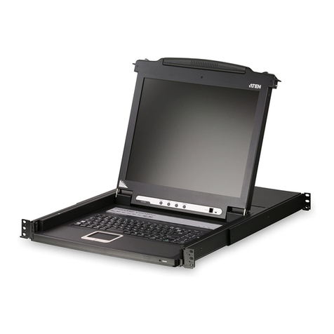
1
2
345
1
2
3
4
5
6
1
2
3
4
5
6
7
8
Press the Exit/Light pushbutton
for two seconds to turn the
LED light ON or Off. (Default: On)
EXIT ILIGHT
123 4
Package Contents
1 CL5800 Dual Rail LCD PS/2–USB
Console with Standard Rack Mount Kit
1 custom KVM cable
1 power cord
1 rmware upgrade cable
1 extension kit
1 user instructions
Support and Documentation Notice
All information, documentation, firmware,
software utilities, and specifications
contained in this package are subject to
change without prior notification by the
manufacturer.
To reduce the environmental impact of
our products, ATEN documentation and
software can be found online at
http://www.aten.com/download/
Technical Support
www.aten.com/support
Scan for more information
Product Page User Manual
Hardware Overview
Front View
Keyboard Module
LCD Module
Rear View
AInstallation
B
Standard Rack Mount
Dual Rail LCD Console
Quick Start Guide
CL5800
Operation
C
Opening the Console Closing the Console
Front-L Bracket Mount
CL5800
Power VGA
USB / PS/2
SPHD
2
5
1
4
6
3 3
Single Stage Installation
© Copyright 2023 ATEN®International Co. Ltd.
ATEN and the ATEN logo are registered trademarks of ATEN International Co., Ltd.
All rights reserved. All other trademarks are the property of their respective owners.
Part No. PAPE-1223-573G Released: 09/2023
Console LCD à double rail CL5800 www.aten.com
A
Description de l’appareil
Vue avant
1Poignée supérieure
2Module LCD
3Module clavier
4Poignée inférieure
5Voyant d’alimentation
6Loquet de libération LCD
7Supports de fi xation pour montage sur bâti
8Eclairage LED
Module clavier
1Loquet de libération du clavier
2Bouton de réinitialisation
3Voyants de verrouillage
4Clavier
5Pavé tactile
6Port USB
Module LCD
1Écran LCD
2Commandes LCD
3Bouton marche/arrêt de l'écran LCD
4Port de mise à jour du microprogramme
5Commutateur de mise à jour du
microprogramme
Vue arrière
1Prise d'alimentation
2Interrupteur
3Section de console externe
4Section des ports KVM
B
Installation
Montage en bâti standard
Un kit de montage sur bâti standard est fourni avec votre CL5800. Ce kit permet de
monter le commutateur sur un bâti, avec une profondeur de 52 à 85 cm.
Pour monter la console CL5800 sur bâti, procédez comme suit :
1. Alors que la première personne continue de maintenir en place la console CL5800,
la deuxième fait glisser les supports en L dans les supports de montage latéraux de la
CL5800 par l'arrière, jusqu'à ce que les brides des supports entrent en contact avec le
bâti, puis visse les supports en L sur le bâti.
2. Une fois les supports en L bien en place, serrez les vis des supports avant.
(En option) Support de montage avant en L
Pour assurer une posture à la fois confortable et sûre, installez les support avant en L qui
permettent d’avancer le rack vers l'avant et ainsi glisser l’unité davantage vers l'extérieur
et ainsi vous permettre d'incliner davantage l'écran LCD.
1. Fixez les supports de montage avant en L à l’avant du rack, en plaçant des vis dans les
languettes pour les maintenir en place.
Remarque : Les vis de rack ne sont pas fournies pour le montage de l’unité. Nous vous
recommandons d'utiliser deux vis M5 x P0,8 de chaque côté.
2. Demandez à une personne de positionner l'unité dans le rack et de la maintenir stable.
Demandez à la deuxième personne de visser les supports avant aux supports avant en L.
Remarque : Les vis de rack ne sont pas fournies pour le montage de l’unité. Nous vous
recommandons d'utiliser une vis M5 x P0,8 de chaque côté.
3. La deuxième personne doit, alors que la première personne maintient l'unité en place,
faire glisser les supports en L gauche et droit dans les supports de montage latéraux de
l'unité par l'arrière, en insérant quatre vis dans les supports pour les fixer en place.
4. Une fois les supports en L fixés, serrez toutes les vis. Assurez-vous de laisser un espace
d’au moins 5,1 cm de chaque côté pour permettre une ventilation adéquate et d’au
moins 12,7 cm à l’arrière pour le cordon d’alimentation et les câbles.
Installation en une étape
1Branchez une extrémité du connecteur SPHD du câble KVM sur le port KVM de la
console LCD.
2Branchez les connecteurs du clavier, du moniteur et de la souris du câble KVM sur les
ports correspondants de la section Console d'un commutateur KVM.
3Si vous installez une console externe, branchez votre clavier, votre moniteur et votre
souris sur leur port respectif sur la section Console de la console LCD. Les ports sont
identifi ables grâce un code de couleur et une icône spécifi que.
4Branchez le câble d'alimentation de la console CL5800 sur la prise d'alimentation de la
console LCD et sur une source d'alimentation.
5Allumez votre installation KVM.
6Allumez la console LCD.
C
Utilisation
Ouverture de la console
1. Tirez les loquets de libération pour dégager la console et tirez le panneau supérieur de
quelques centimètres vers vous.
2. En passant votre main en-dessous, tirez à fond le module clavier jusqu’à ce que vous
entendiez un clic indiquant qu’il est bien en place.
Fermeture de la console
1. Tirez vers vous les loquets de libération situés de chaque côté du clavier pour dégager
le module clavier puis faites légèrement glisser le module vers l’intérieur.
2. Tournez le module LCD complètement vers le bas puis tirez les loquets arrières pour
dégager le module LCD.
CL5800 Dual-Rail-LCD-Konsole www.aten.com
A
Hardwareübersicht
Vorderseitige Ansicht
1Griff oben
2LCD-Modul
3Tastaturmodul
4Griff unten
5LED-Betriebsanzeige
6Entriegelungstaste für LCD
7Arretierungen für Rack-Montage
8LED-Beleuchtung
Tastaturmodul
1Entriegelungstaste für Tastatur
2Reset-Taste
3Verriegelungs-LEDs
4Tastatur
5Touchpad
6USB-Port
LCD-Modul
1LCD-Display
2LCD-Bedienelemente
3Ein-/Ausschalter für LCD-Schirm
4Port zur Firmwareaktualisierung
5Schalter zur Firmwareaktualisierung
Rückseitige Ansicht
1Netzeingangsbuchse
2Netzschalter
3Externer Konsolabschnitt
4KVM-Portabschnitt
B
Installation
Standard-Rackmontage
Mit dem CL5800 wird ein Montagekit für ein Standard-Rack mitgeliefert. Mit diesem Kit
können Sie den Switch in ein Rack mit einer Tiefe von 52 -85 cm einbauen.
Um den CL5800 im Rack einzubauen, gehen Sie folgendermaßen vor:
1. Während die erste Person den CL5800 nach wie vor festhält, schiebt die zweite die
L-Schienen von hinten auf die seitlichen Montagerahmen des CL5800, bis der Flansch
den Rack berührt. Schrauben Sie die L-Schienen anschließend am Rack fest.
2. Nachdem Sie die L-Schienen befestigt haben, ziehen Sie auch die Schrauben an der
Vorderseite fest.
(Optional) Vordere L-Halterung
Um eine bequeme und sichere Körperhaltung einzunehmen, montieren Sie die vordere
L-Halterung, die eine Verlängerung an der Vorderseite des Gestells bietet, sodass das
Gerät weiter nach außen gleiten kann und Sie den LCD-Bildschirm somit weiter neigen
können.
1. Befestigen Sie die linke und rechte vordere L-Halterung an der Vorderseite des
Gestells, indem Sie die Schrauben in Halterungen einsetzen, um sie an Ort und Stelle
festzuschrauben.
Hinweis: Im Lieferumfang sind keine Gestellschrauben für die Montage der Einheit
erhalten. Wir empfehlen die Verwendung von zwei M5 x P0,8 Schrauben auf jeder
Seite.
2. Eine Person soll helfen, die Einheit am Gestell zu positionieren und zu fixieren. Lassen
Sie eine andere Person die vorderen Halterungen an die vordere L-Halterung schrauben.
Hinweis: Im Lieferumfang sind keine Gestellschrauben für die Montage der Einheit
erhalten. Wir empfehlen die Verwendung von einer M5 x P0,8 Schraube auf jeder Seite.
3. Während die erste Person die Einheit noch an Ort und Stelle hält, schiebt die zweite
Person die linken und rechten L-förmigen Halterungen von hinten in die seitlichen
Montagehalterungen der Einheit und schraubt die vier Schrauben in die Halterungen,
um sie zu sichern.
4. Nachdem die L-förmigen Halterungen befestigt sind, ziehen Sie alle Schrauben fest.
Lassen Sie für eine ordnungsgemäße Luftzirkulation an allen Seiten einen Freiraum
von mindestens 5,1 cm und mindestens 12,7 cm auf der Rückseite für die Netz- und
Anschlusskabel.
Einstufige Installation
1Verbinden Sie den SPHD-Stecker eines KVM-Kabels mit dem KVM-Port an der
LCD-Konsole.
2Verbinden Sie die Tastatur-, Monitor- und Mausanschlüsse des KVM-Kabels mit den
betreffenden Ports am Konsolabschnitt eines KVM-Switches.
3Wenn Sie eine externe Konsole anschließen möchten, verbinden Sie Tastatur, Monitor
und Maus mit den zugehörigen Anschlüssen im Konsolabschnitt der LCD-Konsole. Die
Buchsen sind farblich und mit einem Symbol gekennzeichnet.
4Verbinden Sie das Netzkabel des CL5800 mit der Stromeingangsbuchse der
LCD-Konsole und einer Stromquelle.
5Schalten Sie die KVM-Installation ein.
6Schalten Sie die LCD-Konsole ein.
C
Bedienung
Konsole öffnen
1. Ziehen Sie an den Griffen, um die Konsole zu entriegeln, und ziehen Sie das Gerät an
der Vorderseite einige Zentimeter zu sich heran.
2. Greifen Sie unter das Gerät, und ziehen Sie das Tastaturmodul ganz heraus, bis es
einrastet.
Konsole schließen
1. Ziehen Sie die Entriegelungsgriffe, die sich auf jeder Seite der Tastatur befi nden,
zu sich, um das Tastaturmodul freizugeben. Anschließend schieben Sie das Modul
vorsichtig hinein.
2. Klappen Sie das LCD-Modul ganz zu, und ziehen Sie an den rückseitigen Griffen, um es
zu entriegeln.
Consola LCD Dual Rail CL5800 www.aten.com
A
Reseña del hardware
Vista frontal
1Mango superior
2Módulo LCD
3Módulo de teclado
4Mango inferior
5Indicador LED de alimentación
6Botón de desbloqueo LCD
7Muescas para montaje en rack
8Iluminacion LED
Módulo de teclado
1Botón de desbloqueo del teclado
2Tecla de reseteo
3Indicadores LED de bloqueo
4Teclado
5Panel táctil
6Puerto USB
Módulo LCD
1Pantalla LCD
2Controles LCD
3Botón LCD encendido/apagado
4Puerto para actualizaciones del firmware
5Conmutador para actualizar el firmware
Vista posterior
1Entrada de alimentación
2Interruptor de alimentación
3Sección de consola externa
4Sección de puertos KVM
B
Instalación
Soporte para estantería estándar
Con el CL5800 viene un kit de montaje en rack estándar. Con este kit puede montarlo en
un rack con una profundidad entre 52 y 85 cm.
Para montar la CL5800 en el rack, haga lo siguiente:
1. Mientras la primera persona sigue aguantando la CL5800, la segunda desliza los raíles
en L sobre la CL5800 desde la parte trasera hasta que la pestaña del soporte haga
contacto con el rack y luego atornilla los raíles en L al rack.
2. Cuando tenga los raíles en L atornillados, apriete los tornillos frontales de los raíles.
(Opcional) Montaje de soporte en L delantero
Para disfrutar de una postura cómoda y segura, instale los soportes en L delanteros que
proporcionan una extensión en la parte delantera del bastidor, para hacer que la unidad se
pueda deslizar hacia fuera un poco más, permitiéndole inclinar la pantalla LCD aún más.
1. Acople los soportes en L delanteros izquierdo y derecho a la parte delantera de la
estantería, colocando tornillos en las pestañas para fijarlos en su posición.
Nota: No se suministran tornillos de estantería para montar la unidad. Recomendamos
que utilice dos tornillos M5 x P0,8 a cada lado.
2. Una persona debe colocar la unidad en la estantería y sujetarla de forma estable.
Otra segunda persona debe atornillar los soportes delanteros al soporte en L delantero.
Nota: No se suministran tornillos de estantería para montar la unidad. Recomendamos
que utilice un tornillo M5 x P0,8 a cada lado.
3. Mientras la primera persona mantiene la unidad en su lugar, la segunda persona
deslizará los soportes en forma de L izquierdo y derecho hacia los soportes de montaje
del lado de la unidad desde la parte posterior, instalando cuatro tornillos en los soportes
para fijarlos en su posición.
4. Después de haber fijado los soportes en forma de L, apriete todos los tornillos. Deje
al menos 5,1 cm a cada lado para una ventilación adecuada y al menos 12,7 cm en la
parte posterior para que el cable de alimentación se pueda mover holgadamente.
Instalación de una sola etapa
1Enchufe el conector SPHD de un cable KVM al puerto KVM de la consola LCD.
2Enchufe los conectores para teclado, monitor y ratón del cable KVM a los puertos
respectivos de la sección de consola de un conmutador KVM.
3Si instala una consola externa, enchufe el teclado, el monitor y el ratón a los puertos
respectivos de la sección de consola del equipo. Los puertos llevan el código de color
estándar, además de un icono para su identifi cación.
4Enchufe el cable de alimentación de la CL5800 a la entrada de alimentación de la
consola LCD y a una fuente de alimentación.
5Encienda toda la instalación KVM.
6Encienda la consola LCD.
C
Funcionamiento
Abrir la consola
1. Tire de los mangos de desbloqueo para liberar la consola y luego estire de la parte
anterior para acercar la unidad algunos centímetros hacia Usted.
2. Coloque la mano debajo del módulo de teclado y estírelo completamente hacia
adelante hasta que encaje y quede asegurado.
Cerrar la consola
1. Tire los mangos de desbloqueo ubicados en cada lado del teclado hacia Usted para
desbloquear el módulo de teclado y luego deslice el módulo cuidadosamente hacia
dentro.
2. Cierre el módulo LCD completamente y luego estire de los mangos posteriores para
desbloquear el módulo LCD.
Postazione CL5800 LCD a doppio binario www.aten.com
A
Panoramica hardware
Visione anteriore
1Maniglia superiore
2Modulo LCD
3Modulo tastiera
4Maniglia inferiore
5LED d’alimentazione
6Fermo di sganciamento del monitor LCD
7Linguette per il montaggio in rack
8Illuminazione LED
Modulo tastiera
1Fermo di sganciamento della tastiera
2Pulsante Ripristina
3LED di blocco
4Tastiera
5Tavoletta tattile
6Porta USB
Modulo LCD
1Display a cristalli liquidi
2Comandi LCD
3Pulsante di accensione/spegnimento
dello schermo
4Porta per l’aggiornamento del firmware
5Commutatore per l’aggiornamento del
firmware
Visione posteriore
1Presa per l’alimentazione
2Interruttore di alimentazione
3Sezione della console esterna
4Sezione della porta KVM
B
Installazione
Montaggio standard su rack
CL5800 è dotato di un kit standard per il montaggio in rack. Il kit consente di montare lo
switch in rack con una profondità di 52-85cm.
Per montare in rack il CL5800, procedere come segue:
1. Mentre la prima persona continua a tenere in posizione il CL5800, la seconda fa
scivolare le staffe a L nei supporti laterali di montaggio, partendo dal retro, fino a
quando non sono a stretto contatto con il rack e poi avvita le staffe a L al rack.
2. Una volta fissati i supporti a L, stringere le viti dei supporti anteriori.
(Opzionale) Montaggio della staffa anteriore a L
Per avere una postura comoda e corretta, installare le staffe anteriori a L che consentono
di estendere la parte anteriore del rack consentendo all’unità di scivolare ulteriormente e
consentendo di inclinare maggiormente lo schermo LCD.
1. Fissare le staffe anteriori a L, sia la destra che la sinistra, alla parte anteriore del rack,
inserendo delle viti nelle linguetteper fissarle correttamente.
Nota: Non vengono fornite le viti da rack per il montaggio di questa unità. Si consiglia
di utilizzare due viti M5 x P0,8 su ciascun lato.
2. Farsi aiutare da un’altra persona a posizionare l’unità nel rack e a tenerla ferma. La
seconda persona deve avvitare le staffe anteriori alla staffa a L anteriore.
Nota: Non vengono fornite le viti da rack per il montaggio di questa unità. Si consiglia
di utilizzare una vite M5 x P0,8 su ciascun lato.
3. Mentre una persona mantiene l’unità in posizione, la seconda persona fa scivolare
dal retro le staffe a L, sia la destra che la sinistra, nelle staffe di montaggio laterali
dell’unità, stringendo quattro viti nelle staffe per fissarle bene.
4. Dopo aver fissato le staffe a forma di L, stringere tutte le viti. Lasciare uno spazio di
almeno 5,1 cm su entrambi i lati per garantire un'adeguata areazione e uno spazio di
almeno 12,7 cm sul retro per contenere il cavo di alimentazione e lo spazio necessario
intorno.
Installazione a fase singola
1PCollegare l’estremità con il connettore SPHD di un cavo KVM alla porta KVM della
console LCD.
2Inserire i connettori della tastiera, del monitor e del mouse del cavo KVM nelle loro
rispettive porte sulla sezione della console dello switch KVM.
3In caso di installazione di una console esterna, collegare tastiera, mouse e monitor
nelle rispettive porte sulla sezione Console della console LCD. Le porte seguono un
codice a colori e sono contrassegnate da un’icona, per essere identificate facilmente.
4Inserire la spina del cavo dell’alimentazione del CL5800 nella presa dell’alimentazione
della console LCD e in una presa d’alimentazione di rete.
5Accendere l’installazione KVM.
6Accendere la Console LCD.
C
Funzionamento
Apertura della console
1. Per sganciare la console, sollevare i fermi di sganciamento e tirare a sé il pannello
superiore di pochi centimetri.
2. Raggiungere e tirare il modulo della tastiera fino a quando non scatta con un clic al suo
posto.
Chiusura della console
1. Per sganciare il modulo della tastiera, tirare a sé i fermi di sganciamento situati su ogni
lato della stessa e poi farlo scivolare leggermente verso l’interno.
2. Per sganciare il modulo LCD, ruotarlo il verso il basso e poi tirare i fermi di sganciamento
posteriori.
CL5800 Консоль Dual Rail с ЖК-дисплеем www.aten.com
А
Обзор оборудования
Вид спереди
1 Верхняя ручка
2 Модуль ЖК-дисплея
3 Клавиатурный модуль
4 Нижняя ручка
5 Индикатор питания
6 Фиксатор ЖК-дисплея
7 Кронштейны для монтажа в стойку
8 Светодиодная подсветка
Клавиатурный модуль
1 Фиксатор клавиатуры
2 Кнопка сброса настроек
3 Индикаторы блокировки
4 Клавиатура
5 Сенсорная панель
6 USB-разъем
Модуль ЖК-дисплея
1 ЖК-дисплей
2 Кнопки управления ЖК-дисплеем
3 Кнопка включения/отключения
ЖК-дисплея
4 Разъем для обновления прошивки
5 Переключатель обновления
прошивки
Вид сзади
1 Разъем питания
2 Выключатель питания
3 Секция внешней консоли
4 Блок KVM-портов
B
Установка
Стандартный монтаж в стойку
В комплектацию CL5800 входит стандартный набор для монтажа в стойку. С его
помощью переключатель можно установить в стойку глубиной 52–85 см.
Процедура монтажа CL5800 в стойку:
1. Зафиксируйте CL5800 в нужном положении силами одного человека. Поручите
второму задвинуть левый и правый Г-образные кронштейны в боковые посадочные
места на CL5800, действуя с задней стороны устройства. Когда Г-образные
кронштейны встанут вровень со стойкой, закрепите их с помощью винтов.
2. После крепления L-образных кронштейнов затяните винты передних кронштейнов.
(По выбору) Фронтальный монтаж Г-образных кронштейнов
Чтобы создать эргономичные и безопасные условия работы стоя или сидя,
установите фронтальные Г-образные кронштейны, которые удлиняют плечо в
передней части стойки. В результате устройство можно будет выдвинуть еще
дальше и наклонить ЖК-монитор под более удобным углом.
1. Закрепите левый и правый фронтальные Г-образные кронштейны на передней
части стойки, вставив крепежные винты в отверстия для фиксации.
Примечание. В комплектацию устройства не входят крепежные винты для
фиксации в стойке. Рекомендуем использовать с каждой стороны по два винта
M5 x P0,8.
2. Работу выполняют вдвоем. Один человек размещает устройство в стойке и крепко
удерживает его в этом положении. Второй привинчивает к передней части стойки
фронтальные Г-образные кронштейны.
Примечание. В комплектацию устройства не входят крепежные винты для
фиксации в стойке. Рекомендуем использовать с каждой стороны по одному
винту M5 x P0,8.
3. Зафиксируйте устройство в нужном положении силами одного человека.
Поручите второму задвинуть левый и правый Г-образные кронштейны в
боковые посадочные места на устройстве, действуя с его задней стороны.
Затем вставьте в эти кронштейны четыре винта для дальнейшей фиксации.
4. После фиксации Г-образных кронштейнов затяните все винты. Оставьте зазор
по меньшей мере 5,1 см с каждой стороны для надлежащей вентиляции и по
меньшей мере 12,7 см с задней стороны, чтобы уложить шнур питания и кабели.
Одноэтапная установка
1 Подключите кабель KVM к разъему KVM на консоли с ЖК-дисплеем так, чтобы
штекер SPHD вошел в консоль.
2 Подключите штекеры кабеля KVM, передающие сигнал на клавиатуру, мышь и
монитор, к соответствующим разъемам консольного блока KVM-переключателя.
3 В случае установки внешней консоли подключите клавиатуру, мышь и монитор
к соответствующим разъемам консольного блока на консоли с ЖК-дисплеем.
Разъемы легко различить благодаря цветовой кодировке и пиктограммам.
4 Подключите кабель питания CL5800 к разъему питания на консоли с ЖК-дисплеем
и к источнику питания.
5 Подайте питание на систему KVM в сборе.
6 Включите консоль с ЖК-дисплеем.
C
Эксплуатация
Открытие консоли
1. Потяните фиксаторы, чтобы освободить консоль, затем вытяните верхнюю
панель к себе на несколько сантиметров.
2. Нащупайте клавиатурный модуль под ней, затем вытяните его целиком до
щелчка, чтобы он встал на место.
Закрытие консоли
1. Потяните к себе фиксаторы по бокам клавиатуры, чтобы освободить
клавиатурный модуль, затем задвиньте его внутрь, не прилагая большого усилия.
2. Поверните модуль ЖК-дисплея вниз до упора, затем потяните задние
фиксаторы, чтобы освободить его.
CL5800 Dual Rail LCD Console www.aten.com
A
Hardware Overview
Front View
1upper handle
2LCD module
3keyboard module
4lower handle
5power LED
6LCD release catch
7rack mounting tabs
8LED illumination light
Keyboard Module
1keyboard release catch
2reset button
3lock LEDs
4keyboard
5touch pad
6USB port
LCD Module
1LCD display
2LCD controls
3LCD on / off button
4firmware upgrade port
5firmware upgrade switch
Rear View
1power socket
2power switch
3external console section
4KVM port section
B
Installation
Standard Rack Mount
A standard rack mount kit is provided with your CL5800. The kit enables the switch to be
mounted in rack with a depth of 52-85cm.
To rack mount the CL5800, do the following:
1. While the first person still holds the CL5800 in place, the second person slides the L
brackets into the CL5800's side mounting brackets from the rear until the bracket
flanges contact the rack, then screws the L brackets to the rack.
2. After the L brackets have been secured, tighten the front bracket screws.
(Optional) Front-L Bracket Mount
To have a comfortable and safe posture, install the Front-L brackets which provide an
extension at the front of the rack to help the unit slide further out and thus allowing you
to tilt the LCD screen more.
1. Attach the left and right Front-L brackets to the front of the rack, placing screws in the
tabs to secure them in place.
Note: Rack screws are not provided to mount the unit. We recommend that you use
two M5 x P0.8 screws on each side.
2. Have one person position the unit in the rack and hold it steady. Have the second
person screw the front brackets to the Front-L bracket.
Note: Rack screws are. not provided to mount the unit. We recommend that you use
one M5 x P0.8 screws on each side.
3. While the first person still holds the unit in place, the second person slides the left and
right L-shaped brackets into the unit’s side mounting brackets from the rear, installing
four screws in the brackets to secure them in place.
4. After the L-shaped brackets are secured, tighten all the screws. Allow at least 5.1 cm
on each side for proper ventilation, and at least 12.7 cm at the back for the power cord
and cable clearance.
Single Stage Installation
1Plug the SPHD connector end of a KVM cable into the LCD Console's KVM port.
2Plug the keyboard, monitor, and mouse connectors of the KVM cable into their
respective ports on the Console Section of a KVM switch.
3If you are installing an external console, plug your keyboard, monitor, and mouse into
their respective ports on the Console Section of the LCD Console. The ports are color
coded and marked with an icon for easy identification.
4Plug the CL5800’s power cord into the LCD Console's power socket and into a power
source.
5Power up your KVM installation.
6Turn on the power to LCD Console.
C
Operation
Opening the Console
1. Pull the release catches to release the console, and pull the top panel a few centimeters
toward you.
2. Reach underneath and pull the keyboard module all the way out until it clicks into
place.
Closing the Console
1. Pull the release catches located on either side of the keyboard toward you to release
the keyboard module, then slide the module slightly in.
2. Rotate the LCD module all the way down, then pull the rear catches to release the LCD
module.
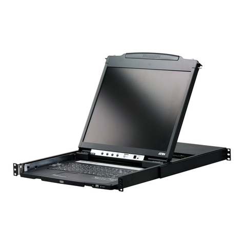
1
2
345
1
2
3
4
5
6
1
2
3
4
5
6
7
8
Press the Exit/Light pushbutton
for two seconds to turn the
LED light ON or Off. (Default: On)
EXIT ILIGHT
123 4
Package Contents
1 CL5800 Dual Rail LCD PS/2–USB
Console with Standard Rack Mount Kit
1 custom KVM cable
1 power cord
1 rmware upgrade cable
1 extension kit
1 user instructions
Support and Documentation Notice
All information, documentation, firmware,
software utilities, and specifications
contained in this package are subject to
change without prior notification by the
manufacturer.
To reduce the environmental impact of
our products, ATEN documentation and
software can be found online at
http://www.aten.com/download/
Technical Support
www.aten.com/support
Scan for more information
Product Page User Manual
Hardware Overview
Front View
Keyboard Module
LCD Module
Rear View
AInstallation
B
Standard Rack Mount
Dual Rail LCD Console
Quick Start Guide
CL5800
Operation
C
Opening the Console Closing the Console
Front-L Bracket Mount
CL5800
Power VGA
USB / PS/2
SPHD
2
5
1
4
6
3 3
Single Stage Installation
© Copyright 2023 ATEN®International Co. Ltd.
ATEN and the ATEN logo are registered trademarks of ATEN International Co., Ltd.
All rights reserved. All other trademarks are the property of their respective owners.
Part No. PAPE-1223-573G Released: 09/2023
Console LCD à double rail CL5800 www.aten.com
A
Description de l’appareil
Vue avant
1Poignée supérieure
2Module LCD
3Module clavier
4Poignée inférieure
5Voyant d’alimentation
6Loquet de libération LCD
7Supports de fi xation pour montage sur bâti
8Eclairage LED
Module clavier
1Loquet de libération du clavier
2Bouton de réinitialisation
3Voyants de verrouillage
4Clavier
5Pavé tactile
6Port USB
Module LCD
1Écran LCD
2Commandes LCD
3Bouton marche/arrêt de l'écran LCD
4Port de mise à jour du microprogramme
5Commutateur de mise à jour du
microprogramme
Vue arrière
1Prise d'alimentation
2Interrupteur
3Section de console externe
4Section des ports KVM
B
Installation
Montage en bâti standard
Un kit de montage sur bâti standard est fourni avec votre CL5800. Ce kit permet de
monter le commutateur sur un bâti, avec une profondeur de 52 à 85 cm.
Pour monter la console CL5800 sur bâti, procédez comme suit :
1. Alors que la première personne continue de maintenir en place la console CL5800,
la deuxième fait glisser les supports en L dans les supports de montage latéraux de la
CL5800 par l'arrière, jusqu'à ce que les brides des supports entrent en contact avec le
bâti, puis visse les supports en L sur le bâti.
2. Une fois les supports en L bien en place, serrez les vis des supports avant.
(En option) Support de montage avant en L
Pour assurer une posture à la fois confortable et sûre, installez les support avant en L qui
permettent d’avancer le rack vers l'avant et ainsi glisser l’unité davantage vers l'extérieur
et ainsi vous permettre d'incliner davantage l'écran LCD.
1. Fixez les supports de montage avant en L à l’avant du rack, en plaçant des vis dans les
languettes pour les maintenir en place.
Remarque : Les vis de rack ne sont pas fournies pour le montage de l’unité. Nous vous
recommandons d'utiliser deux vis M5 x P0,8 de chaque côté.
2. Demandez à une personne de positionner l'unité dans le rack et de la maintenir stable.
Demandez à la deuxième personne de visser les supports avant aux supports avant en L.
Remarque : Les vis de rack ne sont pas fournies pour le montage de l’unité. Nous vous
recommandons d'utiliser une vis M5 x P0,8 de chaque côté.
3. La deuxième personne doit, alors que la première personne maintient l'unité en place,
faire glisser les supports en L gauche et droit dans les supports de montage latéraux de
l'unité par l'arrière, en insérant quatre vis dans les supports pour les fixer en place.
4. Une fois les supports en L fixés, serrez toutes les vis. Assurez-vous de laisser un espace
d’au moins 5,1 cm de chaque côté pour permettre une ventilation adéquate et d’au
moins 12,7 cm à l’arrière pour le cordon d’alimentation et les câbles.
Installation en une étape
1Branchez une extrémité du connecteur SPHD du câble KVM sur le port KVM de la
console LCD.
2Branchez les connecteurs du clavier, du moniteur et de la souris du câble KVM sur les
ports correspondants de la section Console d'un commutateur KVM.
3Si vous installez une console externe, branchez votre clavier, votre moniteur et votre
souris sur leur port respectif sur la section Console de la console LCD. Les ports sont
identifi ables grâce un code de couleur et une icône spécifi que.
4Branchez le câble d'alimentation de la console CL5800 sur la prise d'alimentation de la
console LCD et sur une source d'alimentation.
5Allumez votre installation KVM.
6Allumez la console LCD.
C
Utilisation
Ouverture de la console
1. Tirez les loquets de libération pour dégager la console et tirez le panneau supérieur de
quelques centimètres vers vous.
2. En passant votre main en-dessous, tirez à fond le module clavier jusqu’à ce que vous
entendiez un clic indiquant qu’il est bien en place.
Fermeture de la console
1. Tirez vers vous les loquets de libération situés de chaque côté du clavier pour dégager
le module clavier puis faites légèrement glisser le module vers l’intérieur.
2. Tournez le module LCD complètement vers le bas puis tirez les loquets arrières pour
dégager le module LCD.
CL5800 Dual-Rail-LCD-Konsole www.aten.com
A
Hardwareübersicht
Vorderseitige Ansicht
1Griff oben
2LCD-Modul
3Tastaturmodul
4Griff unten
5LED-Betriebsanzeige
6Entriegelungstaste für LCD
7Arretierungen für Rack-Montage
8LED-Beleuchtung
Tastaturmodul
1Entriegelungstaste für Tastatur
2Reset-Taste
3Verriegelungs-LEDs
4Tastatur
5Touchpad
6USB-Port
LCD-Modul
1LCD-Display
2LCD-Bedienelemente
3Ein-/Ausschalter für LCD-Schirm
4Port zur Firmwareaktualisierung
5Schalter zur Firmwareaktualisierung
Rückseitige Ansicht
1Netzeingangsbuchse
2Netzschalter
3Externer Konsolabschnitt
4KVM-Portabschnitt
B
Installation
Standard-Rackmontage
Mit dem CL5800 wird ein Montagekit für ein Standard-Rack mitgeliefert. Mit diesem Kit
können Sie den Switch in ein Rack mit einer Tiefe von 52 -85 cm einbauen.
Um den CL5800 im Rack einzubauen, gehen Sie folgendermaßen vor:
1. Während die erste Person den CL5800 nach wie vor festhält, schiebt die zweite die
L-Schienen von hinten auf die seitlichen Montagerahmen des CL5800, bis der Flansch
den Rack berührt. Schrauben Sie die L-Schienen anschließend am Rack fest.
2. Nachdem Sie die L-Schienen befestigt haben, ziehen Sie auch die Schrauben an der
Vorderseite fest.
(Optional) Vordere L-Halterung
Um eine bequeme und sichere Körperhaltung einzunehmen, montieren Sie die vordere
L-Halterung, die eine Verlängerung an der Vorderseite des Gestells bietet, sodass das
Gerät weiter nach außen gleiten kann und Sie den LCD-Bildschirm somit weiter neigen
können.
1. Befestigen Sie die linke und rechte vordere L-Halterung an der Vorderseite des
Gestells, indem Sie die Schrauben in Halterungen einsetzen, um sie an Ort und Stelle
festzuschrauben.
Hinweis: Im Lieferumfang sind keine Gestellschrauben für die Montage der Einheit
erhalten. Wir empfehlen die Verwendung von zwei M5 x P0,8 Schrauben auf jeder
Seite.
2. Eine Person soll helfen, die Einheit am Gestell zu positionieren und zu fixieren. Lassen
Sie eine andere Person die vorderen Halterungen an die vordere L-Halterung schrauben.
Hinweis: Im Lieferumfang sind keine Gestellschrauben für die Montage der Einheit
erhalten. Wir empfehlen die Verwendung von einer M5 x P0,8 Schraube auf jeder Seite.
3. Während die erste Person die Einheit noch an Ort und Stelle hält, schiebt die zweite
Person die linken und rechten L-förmigen Halterungen von hinten in die seitlichen
Montagehalterungen der Einheit und schraubt die vier Schrauben in die Halterungen,
um sie zu sichern.
4. Nachdem die L-förmigen Halterungen befestigt sind, ziehen Sie alle Schrauben fest.
Lassen Sie für eine ordnungsgemäße Luftzirkulation an allen Seiten einen Freiraum
von mindestens 5,1 cm und mindestens 12,7 cm auf der Rückseite für die Netz- und
Anschlusskabel.
Einstufige Installation
1Verbinden Sie den SPHD-Stecker eines KVM-Kabels mit dem KVM-Port an der
LCD-Konsole.
2Verbinden Sie die Tastatur-, Monitor- und Mausanschlüsse des KVM-Kabels mit den
betreffenden Ports am Konsolabschnitt eines KVM-Switches.
3Wenn Sie eine externe Konsole anschließen möchten, verbinden Sie Tastatur, Monitor
und Maus mit den zugehörigen Anschlüssen im Konsolabschnitt der LCD-Konsole. Die
Buchsen sind farblich und mit einem Symbol gekennzeichnet.
4Verbinden Sie das Netzkabel des CL5800 mit der Stromeingangsbuchse der
LCD-Konsole und einer Stromquelle.
5Schalten Sie die KVM-Installation ein.
6Schalten Sie die LCD-Konsole ein.
C
Bedienung
Konsole öffnen
1. Ziehen Sie an den Griffen, um die Konsole zu entriegeln, und ziehen Sie das Gerät an
der Vorderseite einige Zentimeter zu sich heran.
2. Greifen Sie unter das Gerät, und ziehen Sie das Tastaturmodul ganz heraus, bis es
einrastet.
Konsole schließen
1. Ziehen Sie die Entriegelungsgriffe, die sich auf jeder Seite der Tastatur befi nden,
zu sich, um das Tastaturmodul freizugeben. Anschließend schieben Sie das Modul
vorsichtig hinein.
2. Klappen Sie das LCD-Modul ganz zu, und ziehen Sie an den rückseitigen Griffen, um es
zu entriegeln.
Consola LCD Dual Rail CL5800 www.aten.com
A
Reseña del hardware
Vista frontal
1Mango superior
2Módulo LCD
3Módulo de teclado
4Mango inferior
5Indicador LED de alimentación
6Botón de desbloqueo LCD
7Muescas para montaje en rack
8Iluminacion LED
Módulo de teclado
1Botón de desbloqueo del teclado
2Tecla de reseteo
3Indicadores LED de bloqueo
4Teclado
5Panel táctil
6Puerto USB
Módulo LCD
1Pantalla LCD
2Controles LCD
3Botón LCD encendido/apagado
4Puerto para actualizaciones del firmware
5Conmutador para actualizar el firmware
Vista posterior
1Entrada de alimentación
2Interruptor de alimentación
3Sección de consola externa
4Sección de puertos KVM
B
Instalación
Soporte para estantería estándar
Con el CL5800 viene un kit de montaje en rack estándar. Con este kit puede montarlo en
un rack con una profundidad entre 52 y 85 cm.
Para montar la CL5800 en el rack, haga lo siguiente:
1. Mientras la primera persona sigue aguantando la CL5800, la segunda desliza los raíles
en L sobre la CL5800 desde la parte trasera hasta que la pestaña del soporte haga
contacto con el rack y luego atornilla los raíles en L al rack.
2. Cuando tenga los raíles en L atornillados, apriete los tornillos frontales de los raíles.
(Opcional) Montaje de soporte en L delantero
Para disfrutar de una postura cómoda y segura, instale los soportes en L delanteros que
proporcionan una extensión en la parte delantera del bastidor, para hacer que la unidad se
pueda deslizar hacia fuera un poco más, permitiéndole inclinar la pantalla LCD aún más.
1. Acople los soportes en L delanteros izquierdo y derecho a la parte delantera de la
estantería, colocando tornillos en las pestañas para fijarlos en su posición.
Nota: No se suministran tornillos de estantería para montar la unidad. Recomendamos
que utilice dos tornillos M5 x P0,8 a cada lado.
2. Una persona debe colocar la unidad en la estantería y sujetarla de forma estable.
Otra segunda persona debe atornillar los soportes delanteros al soporte en L delantero.
Nota: No se suministran tornillos de estantería para montar la unidad. Recomendamos
que utilice un tornillo M5 x P0,8 a cada lado.
3. Mientras la primera persona mantiene la unidad en su lugar, la segunda persona
deslizará los soportes en forma de L izquierdo y derecho hacia los soportes de montaje
del lado de la unidad desde la parte posterior, instalando cuatro tornillos en los soportes
para fijarlos en su posición.
4. Después de haber fijado los soportes en forma de L, apriete todos los tornillos. Deje
al menos 5,1 cm a cada lado para una ventilación adecuada y al menos 12,7 cm en la
parte posterior para que el cable de alimentación se pueda mover holgadamente.
Instalación de una sola etapa
1Enchufe el conector SPHD de un cable KVM al puerto KVM de la consola LCD.
2Enchufe los conectores para teclado, monitor y ratón del cable KVM a los puertos
respectivos de la sección de consola de un conmutador KVM.
3Si instala una consola externa, enchufe el teclado, el monitor y el ratón a los puertos
respectivos de la sección de consola del equipo. Los puertos llevan el código de color
estándar, además de un icono para su identifi cación.
4Enchufe el cable de alimentación de la CL5800 a la entrada de alimentación de la
consola LCD y a una fuente de alimentación.
5Encienda toda la instalación KVM.
6Encienda la consola LCD.
C
Funcionamiento
Abrir la consola
1. Tire de los mangos de desbloqueo para liberar la consola y luego estire de la parte
anterior para acercar la unidad algunos centímetros hacia Usted.
2. Coloque la mano debajo del módulo de teclado y estírelo completamente hacia
adelante hasta que encaje y quede asegurado.
Cerrar la consola
1. Tire los mangos de desbloqueo ubicados en cada lado del teclado hacia Usted para
desbloquear el módulo de teclado y luego deslice el módulo cuidadosamente hacia
dentro.
2. Cierre el módulo LCD completamente y luego estire de los mangos posteriores para
desbloquear el módulo LCD.
Postazione CL5800 LCD a doppio binario www.aten.com
A
Panoramica hardware
Visione anteriore
1Maniglia superiore
2Modulo LCD
3Modulo tastiera
4Maniglia inferiore
5LED d’alimentazione
6Fermo di sganciamento del monitor LCD
7Linguette per il montaggio in rack
8Illuminazione LED
Modulo tastiera
1Fermo di sganciamento della tastiera
2Pulsante Ripristina
3LED di blocco
4Tastiera
5Tavoletta tattile
6Porta USB
Modulo LCD
1Display a cristalli liquidi
2Comandi LCD
3Pulsante di accensione/spegnimento
dello schermo
4Porta per l’aggiornamento del firmware
5Commutatore per l’aggiornamento del
firmware
Visione posteriore
1Presa per l’alimentazione
2Interruttore di alimentazione
3Sezione della console esterna
4Sezione della porta KVM
B
Installazione
Montaggio standard su rack
CL5800 è dotato di un kit standard per il montaggio in rack. Il kit consente di montare lo
switch in rack con una profondità di 52-85cm.
Per montare in rack il CL5800, procedere come segue:
1. Mentre la prima persona continua a tenere in posizione il CL5800, la seconda fa
scivolare le staffe a L nei supporti laterali di montaggio, partendo dal retro, fino a
quando non sono a stretto contatto con il rack e poi avvita le staffe a L al rack.
2. Una volta fissati i supporti a L, stringere le viti dei supporti anteriori.
(Opzionale) Montaggio della staffa anteriore a L
Per avere una postura comoda e corretta, installare le staffe anteriori a L che consentono
di estendere la parte anteriore del rack consentendo all’unità di scivolare ulteriormente e
consentendo di inclinare maggiormente lo schermo LCD.
1. Fissare le staffe anteriori a L, sia la destra che la sinistra, alla parte anteriore del rack,
inserendo delle viti nelle linguetteper fissarle correttamente.
Nota: Non vengono fornite le viti da rack per il montaggio di questa unità. Si consiglia
di utilizzare due viti M5 x P0,8 su ciascun lato.
2. Farsi aiutare da un’altra persona a posizionare l’unità nel rack e a tenerla ferma. La
seconda persona deve avvitare le staffe anteriori alla staffa a L anteriore.
Nota: Non vengono fornite le viti da rack per il montaggio di questa unità. Si consiglia
di utilizzare una vite M5 x P0,8 su ciascun lato.
3. Mentre una persona mantiene l’unità in posizione, la seconda persona fa scivolare
dal retro le staffe a L, sia la destra che la sinistra, nelle staffe di montaggio laterali
dell’unità, stringendo quattro viti nelle staffe per fissarle bene.
4. Dopo aver fissato le staffe a forma di L, stringere tutte le viti. Lasciare uno spazio di
almeno 5,1 cm su entrambi i lati per garantire un'adeguata areazione e uno spazio di
almeno 12,7 cm sul retro per contenere il cavo di alimentazione e lo spazio necessario
intorno.
Installazione a fase singola
1PCollegare l’estremità con il connettore SPHD di un cavo KVM alla porta KVM della
console LCD.
2Inserire i connettori della tastiera, del monitor e del mouse del cavo KVM nelle loro
rispettive porte sulla sezione della console dello switch KVM.
3In caso di installazione di una console esterna, collegare tastiera, mouse e monitor
nelle rispettive porte sulla sezione Console della console LCD. Le porte seguono un
codice a colori e sono contrassegnate da un’icona, per essere identificate facilmente.
4Inserire la spina del cavo dell’alimentazione del CL5800 nella presa dell’alimentazione
della console LCD e in una presa d’alimentazione di rete.
5Accendere l’installazione KVM.
6Accendere la Console LCD.
C
Funzionamento
Apertura della console
1. Per sganciare la console, sollevare i fermi di sganciamento e tirare a sé il pannello
superiore di pochi centimetri.
2. Raggiungere e tirare il modulo della tastiera fino a quando non scatta con un clic al suo
posto.
Chiusura della console
1. Per sganciare il modulo della tastiera, tirare a sé i fermi di sganciamento situati su ogni
lato della stessa e poi farlo scivolare leggermente verso l’interno.
2. Per sganciare il modulo LCD, ruotarlo il verso il basso e poi tirare i fermi di sganciamento
posteriori.
CL5800 Консоль Dual Rail с ЖК-дисплеем www.aten.com
А
Обзор оборудования
Вид спереди
1 Верхняя ручка
2 Модуль ЖК-дисплея
3 Клавиатурный модуль
4 Нижняя ручка
5 Индикатор питания
6 Фиксатор ЖК-дисплея
7 Кронштейны для монтажа в стойку
8 Светодиодная подсветка
Клавиатурный модуль
1 Фиксатор клавиатуры
2 Кнопка сброса настроек
3 Индикаторы блокировки
4 Клавиатура
5 Сенсорная панель
6 USB-разъем
Модуль ЖК-дисплея
1 ЖК-дисплей
2 Кнопки управления ЖК-дисплеем
3 Кнопка включения/отключения
ЖК-дисплея
4 Разъем для обновления прошивки
5 Переключатель обновления
прошивки
Вид сзади
1 Разъем питания
2 Выключатель питания
3 Секция внешней консоли
4 Блок KVM-портов
B
Установка
Стандартный монтаж в стойку
В комплектацию CL5800 входит стандартный набор для монтажа в стойку. С его
помощью переключатель можно установить в стойку глубиной 52–85 см.
Процедура монтажа CL5800 в стойку:
1. Зафиксируйте CL5800 в нужном положении силами одного человека. Поручите
второму задвинуть левый и правый Г-образные кронштейны в боковые посадочные
места на CL5800, действуя с задней стороны устройства. Когда Г-образные
кронштейны встанут вровень со стойкой, закрепите их с помощью винтов.
2. После крепления L-образных кронштейнов затяните винты передних кронштейнов.
(По выбору) Фронтальный монтаж Г-образных кронштейнов
Чтобы создать эргономичные и безопасные условия работы стоя или сидя,
установите фронтальные Г-образные кронштейны, которые удлиняют плечо в
передней части стойки. В результате устройство можно будет выдвинуть еще
дальше и наклонить ЖК-монитор под более удобным углом.
1. Закрепите левый и правый фронтальные Г-образные кронштейны на передней
части стойки, вставив крепежные винты в отверстия для фиксации.
Примечание. В комплектацию устройства не входят крепежные винты для
фиксации в стойке. Рекомендуем использовать с каждой стороны по два винта
M5 x P0,8.
2. Работу выполняют вдвоем. Один человек размещает устройство в стойке и крепко
удерживает его в этом положении. Второй привинчивает к передней части стойки
фронтальные Г-образные кронштейны.
Примечание. В комплектацию устройства не входят крепежные винты для
фиксации в стойке. Рекомендуем использовать с каждой стороны по одному
винту M5 x P0,8.
3. Зафиксируйте устройство в нужном положении силами одного человека.
Поручите второму задвинуть левый и правый Г-образные кронштейны в
боковые посадочные места на устройстве, действуя с его задней стороны.
Затем вставьте в эти кронштейны четыре винта для дальнейшей фиксации.
4. После фиксации Г-образных кронштейнов затяните все винты. Оставьте зазор
по меньшей мере 5,1 см с каждой стороны для надлежащей вентиляции и по
меньшей мере 12,7 см с задней стороны, чтобы уложить шнур питания и кабели.
Одноэтапная установка
1 Подключите кабель KVM к разъему KVM на консоли с ЖК-дисплеем так, чтобы
штекер SPHD вошел в консоль.
2 Подключите штекеры кабеля KVM, передающие сигнал на клавиатуру, мышь и
монитор, к соответствующим разъемам консольного блока KVM-переключателя.
3 В случае установки внешней консоли подключите клавиатуру, мышь и монитор
к соответствующим разъемам консольного блока на консоли с ЖК-дисплеем.
Разъемы легко различить благодаря цветовой кодировке и пиктограммам.
4 Подключите кабель питания CL5800 к разъему питания на консоли с ЖК-дисплеем
и к источнику питания.
5 Подайте питание на систему KVM в сборе.
6 Включите консоль с ЖК-дисплеем.
C
Эксплуатация
Открытие консоли
1. Потяните фиксаторы, чтобы освободить консоль, затем вытяните верхнюю
панель к себе на несколько сантиметров.
2. Нащупайте клавиатурный модуль под ней, затем вытяните его целиком до
щелчка, чтобы он встал на место.
Закрытие консоли
1. Потяните к себе фиксаторы по бокам клавиатуры, чтобы освободить
клавиатурный модуль, затем задвиньте его внутрь, не прилагая большого усилия.
2. Поверните модуль ЖК-дисплея вниз до упора, затем потяните задние
фиксаторы, чтобы освободить его.
CL5800 Dual Rail LCD Console www.aten.com
A
Hardware Overview
Front View
1upper handle
2LCD module
3keyboard module
4lower handle
5power LED
6LCD release catch
7rack mounting tabs
8LED illumination light
Keyboard Module
1keyboard release catch
2reset button
3lock LEDs
4keyboard
5touch pad
6USB port
LCD Module
1LCD display
2LCD controls
3LCD on / off button
4firmware upgrade port
5firmware upgrade switch
Rear View
1power socket
2power switch
3external console section
4KVM port section
B
Installation
Standard Rack Mount
A standard rack mount kit is provided with your CL5800. The kit enables the switch to be
mounted in rack with a depth of 52-85cm.
To rack mount the CL5800, do the following:
1. While the first person still holds the CL5800 in place, the second person slides the L
brackets into the CL5800's side mounting brackets from the rear until the bracket
flanges contact the rack, then screws the L brackets to the rack.
2. After the L brackets have been secured, tighten the front bracket screws.
(Optional) Front-L Bracket Mount
To have a comfortable and safe posture, install the Front-L brackets which provide an
extension at the front of the rack to help the unit slide further out and thus allowing you
to tilt the LCD screen more.
1. Attach the left and right Front-L brackets to the front of the rack, placing screws in the
tabs to secure them in place.
Note: Rack screws are not provided to mount the unit. We recommend that you use
two M5 x P0.8 screws on each side.
2. Have one person position the unit in the rack and hold it steady. Have the second
person screw the front brackets to the Front-L bracket.
Note: Rack screws are. not provided to mount the unit. We recommend that you use
one M5 x P0.8 screws on each side.
3. While the first person still holds the unit in place, the second person slides the left and
right L-shaped brackets into the unit’s side mounting brackets from the rear, installing
four screws in the brackets to secure them in place.
4. After the L-shaped brackets are secured, tighten all the screws. Allow at least 5.1 cm
on each side for proper ventilation, and at least 12.7 cm at the back for the power cord
and cable clearance.
Single Stage Installation
1Plug the SPHD connector end of a KVM cable into the LCD Console's KVM port.
2Plug the keyboard, monitor, and mouse connectors of the KVM cable into their
respective ports on the Console Section of a KVM switch.
3If you are installing an external console, plug your keyboard, monitor, and mouse into
their respective ports on the Console Section of the LCD Console. The ports are color
coded and marked with an icon for easy identification.
4Plug the CL5800’s power cord into the LCD Console's power socket and into a power
source.
5Power up your KVM installation.
6Turn on the power to LCD Console.
C
Operation
Opening the Console
1. Pull the release catches to release the console, and pull the top panel a few centimeters
toward you.
2. Reach underneath and pull the keyboard module all the way out until it clicks into
place.
Closing the Console
1. Pull the release catches located on either side of the keyboard toward you to release
the keyboard module, then slide the module slightly in.
2. Rotate the LCD module all the way down, then pull the rear catches to release the LCD
module.
1
2
345
1
2
3
4
5
6
1
2
3
4
5
6
7
8
Press the Exit/Light pushbutton
for two seconds to turn the
LED light ON or Off. (Default: On)
EXIT ILIGHT
123 4
Package Contents
1 CL5800 Dual Rail LCD PS/2–USB
Console with Standard Rack Mount Kit
1 custom KVM cable
1 power cord
1 rmware upgrade cable
1 extension kit
1 user instructions
Support and Documentation Notice
All information, documentation, firmware,
software utilities, and specifications
contained in this package are subject to
change without prior notification by the
manufacturer.
To reduce the environmental impact of
our products, ATEN documentation and
software can be found online at
http://www.aten.com/download/
Technical Support
www.aten.com/support
Scan for more information
Product Page User Manual
Hardware Overview
Front View
Keyboard Module
LCD Module
Rear View
AInstallation
B
Standard Rack Mount
Dual Rail LCD Console
Quick Start Guide
CL5800
Operation
C
Opening the Console Closing the Console
Front-L Bracket Mount
CL5800
Power VGA
USB / PS/2
SPHD
2
5
1
4
6
3 3
Single Stage Installation
© Copyright 2023 ATEN®International Co. Ltd.
ATEN and the ATEN logo are registered trademarks of ATEN International Co., Ltd.
All rights reserved. All other trademarks are the property of their respective owners.
Part No. PAPE-1223-573G Released: 09/2023
Console LCD à double rail CL5800 www.aten.com
A
Description de l’appareil
Vue avant
1Poignée supérieure
2Module LCD
3Module clavier
4Poignée inférieure
5Voyant d’alimentation
6Loquet de libération LCD
7Supports de fi xation pour montage sur bâti
8Eclairage LED
Module clavier
1Loquet de libération du clavier
2Bouton de réinitialisation
3Voyants de verrouillage
4Clavier
5Pavé tactile
6Port USB
Module LCD
1Écran LCD
2Commandes LCD
3Bouton marche/arrêt de l'écran LCD
4Port de mise à jour du microprogramme
5Commutateur de mise à jour du
microprogramme
Vue arrière
1Prise d'alimentation
2Interrupteur
3Section de console externe
4Section des ports KVM
B
Installation
Montage en bâti standard
Un kit de montage sur bâti standard est fourni avec votre CL5800. Ce kit permet de
monter le commutateur sur un bâti, avec une profondeur de 52 à 85 cm.
Pour monter la console CL5800 sur bâti, procédez comme suit :
1. Alors que la première personne continue de maintenir en place la console CL5800,
la deuxième fait glisser les supports en L dans les supports de montage latéraux de la
CL5800 par l'arrière, jusqu'à ce que les brides des supports entrent en contact avec le
bâti, puis visse les supports en L sur le bâti.
2. Une fois les supports en L bien en place, serrez les vis des supports avant.
(En option) Support de montage avant en L
Pour assurer une posture à la fois confortable et sûre, installez les support avant en L qui
permettent d’avancer le rack vers l'avant et ainsi glisser l’unité davantage vers l'extérieur
et ainsi vous permettre d'incliner davantage l'écran LCD.
1. Fixez les supports de montage avant en L à l’avant du rack, en plaçant des vis dans les
languettes pour les maintenir en place.
Remarque : Les vis de rack ne sont pas fournies pour le montage de l’unité. Nous vous
recommandons d'utiliser deux vis M5 x P0,8 de chaque côté.
2. Demandez à une personne de positionner l'unité dans le rack et de la maintenir stable.
Demandez à la deuxième personne de visser les supports avant aux supports avant en L.
Remarque : Les vis de rack ne sont pas fournies pour le montage de l’unité. Nous vous
recommandons d'utiliser une vis M5 x P0,8 de chaque côté.
3. La deuxième personne doit, alors que la première personne maintient l'unité en place,
faire glisser les supports en L gauche et droit dans les supports de montage latéraux de
l'unité par l'arrière, en insérant quatre vis dans les supports pour les fixer en place.
4. Une fois les supports en L fixés, serrez toutes les vis. Assurez-vous de laisser un espace
d’au moins 5,1 cm de chaque côté pour permettre une ventilation adéquate et d’au
moins 12,7 cm à l’arrière pour le cordon d’alimentation et les câbles.
Installation en une étape
1Branchez une extrémité du connecteur SPHD du câble KVM sur le port KVM de la
console LCD.
2Branchez les connecteurs du clavier, du moniteur et de la souris du câble KVM sur les
ports correspondants de la section Console d'un commutateur KVM.
3Si vous installez une console externe, branchez votre clavier, votre moniteur et votre
souris sur leur port respectif sur la section Console de la console LCD. Les ports sont
identifi ables grâce un code de couleur et une icône spécifi que.
4Branchez le câble d'alimentation de la console CL5800 sur la prise d'alimentation de la
console LCD et sur une source d'alimentation.
5Allumez votre installation KVM.
6Allumez la console LCD.
C
Utilisation
Ouverture de la console
1. Tirez les loquets de libération pour dégager la console et tirez le panneau supérieur de
quelques centimètres vers vous.
2. En passant votre main en-dessous, tirez à fond le module clavier jusqu’à ce que vous
entendiez un clic indiquant qu’il est bien en place.
Fermeture de la console
1. Tirez vers vous les loquets de libération situés de chaque côté du clavier pour dégager
le module clavier puis faites légèrement glisser le module vers l’intérieur.
2. Tournez le module LCD complètement vers le bas puis tirez les loquets arrières pour
dégager le module LCD.
CL5800 Dual-Rail-LCD-Konsole www.aten.com
A
Hardwareübersicht
Vorderseitige Ansicht
1Griff oben
2LCD-Modul
3Tastaturmodul
4Griff unten
5LED-Betriebsanzeige
6Entriegelungstaste für LCD
7Arretierungen für Rack-Montage
8LED-Beleuchtung
Tastaturmodul
1Entriegelungstaste für Tastatur
2Reset-Taste
3Verriegelungs-LEDs
4Tastatur
5Touchpad
6USB-Port
LCD-Modul
1LCD-Display
2LCD-Bedienelemente
3Ein-/Ausschalter für LCD-Schirm
4Port zur Firmwareaktualisierung
5Schalter zur Firmwareaktualisierung
Rückseitige Ansicht
1Netzeingangsbuchse
2Netzschalter
3Externer Konsolabschnitt
4KVM-Portabschnitt
B
Installation
Standard-Rackmontage
Mit dem CL5800 wird ein Montagekit für ein Standard-Rack mitgeliefert. Mit diesem Kit
können Sie den Switch in ein Rack mit einer Tiefe von 52 -85 cm einbauen.
Um den CL5800 im Rack einzubauen, gehen Sie folgendermaßen vor:
1. Während die erste Person den CL5800 nach wie vor festhält, schiebt die zweite die
L-Schienen von hinten auf die seitlichen Montagerahmen des CL5800, bis der Flansch
den Rack berührt. Schrauben Sie die L-Schienen anschließend am Rack fest.
2. Nachdem Sie die L-Schienen befestigt haben, ziehen Sie auch die Schrauben an der
Vorderseite fest.
(Optional) Vordere L-Halterung
Um eine bequeme und sichere Körperhaltung einzunehmen, montieren Sie die vordere
L-Halterung, die eine Verlängerung an der Vorderseite des Gestells bietet, sodass das
Gerät weiter nach außen gleiten kann und Sie den LCD-Bildschirm somit weiter neigen
können.
1. Befestigen Sie die linke und rechte vordere L-Halterung an der Vorderseite des
Gestells, indem Sie die Schrauben in Halterungen einsetzen, um sie an Ort und Stelle
festzuschrauben.
Hinweis: Im Lieferumfang sind keine Gestellschrauben für die Montage der Einheit
erhalten. Wir empfehlen die Verwendung von zwei M5 x P0,8 Schrauben auf jeder
Seite.
2. Eine Person soll helfen, die Einheit am Gestell zu positionieren und zu fixieren. Lassen
Sie eine andere Person die vorderen Halterungen an die vordere L-Halterung schrauben.
Hinweis: Im Lieferumfang sind keine Gestellschrauben für die Montage der Einheit
erhalten. Wir empfehlen die Verwendung von einer M5 x P0,8 Schraube auf jeder Seite.
3. Während die erste Person die Einheit noch an Ort und Stelle hält, schiebt die zweite
Person die linken und rechten L-förmigen Halterungen von hinten in die seitlichen
Montagehalterungen der Einheit und schraubt die vier Schrauben in die Halterungen,
um sie zu sichern.
4. Nachdem die L-förmigen Halterungen befestigt sind, ziehen Sie alle Schrauben fest.
Lassen Sie für eine ordnungsgemäße Luftzirkulation an allen Seiten einen Freiraum
von mindestens 5,1 cm und mindestens 12,7 cm auf der Rückseite für die Netz- und
Anschlusskabel.
Einstufige Installation
1Verbinden Sie den SPHD-Stecker eines KVM-Kabels mit dem KVM-Port an der
LCD-Konsole.
2Verbinden Sie die Tastatur-, Monitor- und Mausanschlüsse des KVM-Kabels mit den
betreffenden Ports am Konsolabschnitt eines KVM-Switches.
3Wenn Sie eine externe Konsole anschließen möchten, verbinden Sie Tastatur, Monitor
und Maus mit den zugehörigen Anschlüssen im Konsolabschnitt der LCD-Konsole. Die
Buchsen sind farblich und mit einem Symbol gekennzeichnet.
4Verbinden Sie das Netzkabel des CL5800 mit der Stromeingangsbuchse der
LCD-Konsole und einer Stromquelle.
5Schalten Sie die KVM-Installation ein.
6Schalten Sie die LCD-Konsole ein.
C
Bedienung
Konsole öffnen
1. Ziehen Sie an den Griffen, um die Konsole zu entriegeln, und ziehen Sie das Gerät an
der Vorderseite einige Zentimeter zu sich heran.
2. Greifen Sie unter das Gerät, und ziehen Sie das Tastaturmodul ganz heraus, bis es
einrastet.
Konsole schließen
1. Ziehen Sie die Entriegelungsgriffe, die sich auf jeder Seite der Tastatur befi nden,
zu sich, um das Tastaturmodul freizugeben. Anschließend schieben Sie das Modul
vorsichtig hinein.
2. Klappen Sie das LCD-Modul ganz zu, und ziehen Sie an den rückseitigen Griffen, um es
zu entriegeln.
Consola LCD Dual Rail CL5800 www.aten.com
A
Reseña del hardware
Vista frontal
1Mango superior
2Módulo LCD
3Módulo de teclado
4Mango inferior
5Indicador LED de alimentación
6Botón de desbloqueo LCD
7Muescas para montaje en rack
8Iluminacion LED
Módulo de teclado
1Botón de desbloqueo del teclado
2Tecla de reseteo
3Indicadores LED de bloqueo
4Teclado
5Panel táctil
6Puerto USB
Módulo LCD
1Pantalla LCD
2Controles LCD
3Botón LCD encendido/apagado
4Puerto para actualizaciones del firmware
5Conmutador para actualizar el firmware
Vista posterior
1Entrada de alimentación
2Interruptor de alimentación
3Sección de consola externa
4Sección de puertos KVM
B
Instalación
Soporte para estantería estándar
Con el CL5800 viene un kit de montaje en rack estándar. Con este kit puede montarlo en
un rack con una profundidad entre 52 y 85 cm.
Para montar la CL5800 en el rack, haga lo siguiente:
1. Mientras la primera persona sigue aguantando la CL5800, la segunda desliza los raíles
en L sobre la CL5800 desde la parte trasera hasta que la pestaña del soporte haga
contacto con el rack y luego atornilla los raíles en L al rack.
2. Cuando tenga los raíles en L atornillados, apriete los tornillos frontales de los raíles.
(Opcional) Montaje de soporte en L delantero
Para disfrutar de una postura cómoda y segura, instale los soportes en L delanteros que
proporcionan una extensión en la parte delantera del bastidor, para hacer que la unidad se
pueda deslizar hacia fuera un poco más, permitiéndole inclinar la pantalla LCD aún más.
1. Acople los soportes en L delanteros izquierdo y derecho a la parte delantera de la
estantería, colocando tornillos en las pestañas para fijarlos en su posición.
Nota: No se suministran tornillos de estantería para montar la unidad. Recomendamos
que utilice dos tornillos M5 x P0,8 a cada lado.
2. Una persona debe colocar la unidad en la estantería y sujetarla de forma estable.
Otra segunda persona debe atornillar los soportes delanteros al soporte en L delantero.
Nota: No se suministran tornillos de estantería para montar la unidad. Recomendamos
que utilice un tornillo M5 x P0,8 a cada lado.
3. Mientras la primera persona mantiene la unidad en su lugar, la segunda persona
deslizará los soportes en forma de L izquierdo y derecho hacia los soportes de montaje
del lado de la unidad desde la parte posterior, instalando cuatro tornillos en los soportes
para fijarlos en su posición.
4. Después de haber fijado los soportes en forma de L, apriete todos los tornillos. Deje
al menos 5,1 cm a cada lado para una ventilación adecuada y al menos 12,7 cm en la
parte posterior para que el cable de alimentación se pueda mover holgadamente.
Instalación de una sola etapa
1Enchufe el conector SPHD de un cable KVM al puerto KVM de la consola LCD.
2Enchufe los conectores para teclado, monitor y ratón del cable KVM a los puertos
respectivos de la sección de consola de un conmutador KVM.
3Si instala una consola externa, enchufe el teclado, el monitor y el ratón a los puertos
respectivos de la sección de consola del equipo. Los puertos llevan el código de color
estándar, además de un icono para su identifi cación.
4Enchufe el cable de alimentación de la CL5800 a la entrada de alimentación de la
consola LCD y a una fuente de alimentación.
5Encienda toda la instalación KVM.
6Encienda la consola LCD.
C
Funcionamiento
Abrir la consola
1. Tire de los mangos de desbloqueo para liberar la consola y luego estire de la parte
anterior para acercar la unidad algunos centímetros hacia Usted.
2. Coloque la mano debajo del módulo de teclado y estírelo completamente hacia
adelante hasta que encaje y quede asegurado.
Cerrar la consola
1. Tire los mangos de desbloqueo ubicados en cada lado del teclado hacia Usted para
desbloquear el módulo de teclado y luego deslice el módulo cuidadosamente hacia
dentro.
2. Cierre el módulo LCD completamente y luego estire de los mangos posteriores para
desbloquear el módulo LCD.
Postazione CL5800 LCD a doppio binario www.aten.com
A
Panoramica hardware
Visione anteriore
1Maniglia superiore
2Modulo LCD
3Modulo tastiera
4Maniglia inferiore
5LED d’alimentazione
6Fermo di sganciamento del monitor LCD
7Linguette per il montaggio in rack
8Illuminazione LED
Modulo tastiera
1Fermo di sganciamento della tastiera
2Pulsante Ripristina
3LED di blocco
4Tastiera
5Tavoletta tattile
6Porta USB
Modulo LCD
1Display a cristalli liquidi
2Comandi LCD
3Pulsante di accensione/spegnimento
dello schermo
4Porta per l’aggiornamento del firmware
5Commutatore per l’aggiornamento del
firmware
Visione posteriore
1Presa per l’alimentazione
2Interruttore di alimentazione
3Sezione della console esterna
4Sezione della porta KVM
B
Installazione
Montaggio standard su rack
CL5800 è dotato di un kit standard per il montaggio in rack. Il kit consente di montare lo
switch in rack con una profondità di 52-85cm.
Per montare in rack il CL5800, procedere come segue:
1. Mentre la prima persona continua a tenere in posizione il CL5800, la seconda fa
scivolare le staffe a L nei supporti laterali di montaggio, partendo dal retro, fino a
quando non sono a stretto contatto con il rack e poi avvita le staffe a L al rack.
2. Una volta fissati i supporti a L, stringere le viti dei supporti anteriori.
(Opzionale) Montaggio della staffa anteriore a L
Per avere una postura comoda e corretta, installare le staffe anteriori a L che consentono
di estendere la parte anteriore del rack consentendo all’unità di scivolare ulteriormente e
consentendo di inclinare maggiormente lo schermo LCD.
1. Fissare le staffe anteriori a L, sia la destra che la sinistra, alla parte anteriore del rack,
inserendo delle viti nelle linguetteper fissarle correttamente.
Nota: Non vengono fornite le viti da rack per il montaggio di questa unità. Si consiglia
di utilizzare due viti M5 x P0,8 su ciascun lato.
2. Farsi aiutare da un’altra persona a posizionare l’unità nel rack e a tenerla ferma. La
seconda persona deve avvitare le staffe anteriori alla staffa a L anteriore.
Nota: Non vengono fornite le viti da rack per il montaggio di questa unità. Si consiglia
di utilizzare una vite M5 x P0,8 su ciascun lato.
3. Mentre una persona mantiene l’unità in posizione, la seconda persona fa scivolare
dal retro le staffe a L, sia la destra che la sinistra, nelle staffe di montaggio laterali
dell’unità, stringendo quattro viti nelle staffe per fissarle bene.
4. Dopo aver fissato le staffe a forma di L, stringere tutte le viti. Lasciare uno spazio di
almeno 5,1 cm su entrambi i lati per garantire un'adeguata areazione e uno spazio di
almeno 12,7 cm sul retro per contenere il cavo di alimentazione e lo spazio necessario
intorno.
Installazione a fase singola
1PCollegare l’estremità con il connettore SPHD di un cavo KVM alla porta KVM della
console LCD.
2Inserire i connettori della tastiera, del monitor e del mouse del cavo KVM nelle loro
rispettive porte sulla sezione della console dello switch KVM.
3In caso di installazione di una console esterna, collegare tastiera, mouse e monitor
nelle rispettive porte sulla sezione Console della console LCD. Le porte seguono un
codice a colori e sono contrassegnate da un’icona, per essere identificate facilmente.
4Inserire la spina del cavo dell’alimentazione del CL5800 nella presa dell’alimentazione
della console LCD e in una presa d’alimentazione di rete.
5Accendere l’installazione KVM.
6Accendere la Console LCD.
C
Funzionamento
Apertura della console
1. Per sganciare la console, sollevare i fermi di sganciamento e tirare a sé il pannello
superiore di pochi centimetri.
2. Raggiungere e tirare il modulo della tastiera fino a quando non scatta con un clic al suo
posto.
Chiusura della console
1. Per sganciare il modulo della tastiera, tirare a sé i fermi di sganciamento situati su ogni
lato della stessa e poi farlo scivolare leggermente verso l’interno.
2. Per sganciare il modulo LCD, ruotarlo il verso il basso e poi tirare i fermi di sganciamento
posteriori.
CL5800 Консоль Dual Rail с ЖК-дисплеем www.aten.com
А
Обзор оборудования
Вид спереди
1 Верхняя ручка
2 Модуль ЖК-дисплея
3 Клавиатурный модуль
4 Нижняя ручка
5 Индикатор питания
6 Фиксатор ЖК-дисплея
7 Кронштейны для монтажа в стойку
8 Светодиодная подсветка
Клавиатурный модуль
1 Фиксатор клавиатуры
2 Кнопка сброса настроек
3 Индикаторы блокировки
4 Клавиатура
5 Сенсорная панель
6 USB-разъем
Модуль ЖК-дисплея
1 ЖК-дисплей
2 Кнопки управления ЖК-дисплеем
3 Кнопка включения/отключения
ЖК-дисплея
4 Разъем для обновления прошивки
5 Переключатель обновления
прошивки
Вид сзади
1 Разъем питания
2 Выключатель питания
3 Секция внешней консоли
4 Блок KVM-портов
B
Установка
Стандартный монтаж в стойку
В комплектацию CL5800 входит стандартный набор для монтажа в стойку. С его
помощью переключатель можно установить в стойку глубиной 52–85 см.
Процедура монтажа CL5800 в стойку:
1. Зафиксируйте CL5800 в нужном положении силами одного человека. Поручите
второму задвинуть левый и правый Г-образные кронштейны в боковые посадочные
места на CL5800, действуя с задней стороны устройства. Когда Г-образные
кронштейны встанут вровень со стойкой, закрепите их с помощью винтов.
2. После крепления L-образных кронштейнов затяните винты передних кронштейнов.
(По выбору) Фронтальный монтаж Г-образных кронштейнов
Чтобы создать эргономичные и безопасные условия работы стоя или сидя,
установите фронтальные Г-образные кронштейны, которые удлиняют плечо в
передней части стойки. В результате устройство можно будет выдвинуть еще
дальше и наклонить ЖК-монитор под более удобным углом.
1. Закрепите левый и правый фронтальные Г-образные кронштейны на передней
части стойки, вставив крепежные винты в отверстия для фиксации.
Примечание. В комплектацию устройства не входят крепежные винты для
фиксации в стойке. Рекомендуем использовать с каждой стороны по два винта
M5 x P0,8.
2. Работу выполняют вдвоем. Один человек размещает устройство в стойке и крепко
удерживает его в этом положении. Второй привинчивает к передней части стойки
фронтальные Г-образные кронштейны.
Примечание. В комплектацию устройства не входят крепежные винты для
фиксации в стойке. Рекомендуем использовать с каждой стороны по одному
винту M5 x P0,8.
3. Зафиксируйте устройство в нужном положении силами одного человека.
Поручите второму задвинуть левый и правый Г-образные кронштейны в
боковые посадочные места на устройстве, действуя с его задней стороны.
Затем вставьте в эти кронштейны четыре винта для дальнейшей фиксации.
4. После фиксации Г-образных кронштейнов затяните все винты. Оставьте зазор
по меньшей мере 5,1 см с каждой стороны для надлежащей вентиляции и по
меньшей мере 12,7 см с задней стороны, чтобы уложить шнур питания и кабели.
Одноэтапная установка
1 Подключите кабель KVM к разъему KVM на консоли с ЖК-дисплеем так, чтобы
штекер SPHD вошел в консоль.
2 Подключите штекеры кабеля KVM, передающие сигнал на клавиатуру, мышь и
монитор, к соответствующим разъемам консольного блока KVM-переключателя.
3 В случае установки внешней консоли подключите клавиатуру, мышь и монитор
к соответствующим разъемам консольного блока на консоли с ЖК-дисплеем.
Разъемы легко различить благодаря цветовой кодировке и пиктограммам.
4 Подключите кабель питания CL5800 к разъему питания на консоли с ЖК-дисплеем
и к источнику питания.
5 Подайте питание на систему KVM в сборе.
6 Включите консоль с ЖК-дисплеем.
C
Эксплуатация
Открытие консоли
1. Потяните фиксаторы, чтобы освободить консоль, затем вытяните верхнюю
панель к себе на несколько сантиметров.
2. Нащупайте клавиатурный модуль под ней, затем вытяните его целиком до
щелчка, чтобы он встал на место.
Закрытие консоли
1. Потяните к себе фиксаторы по бокам клавиатуры, чтобы освободить
клавиатурный модуль, затем задвиньте его внутрь, не прилагая большого усилия.
2. Поверните модуль ЖК-дисплея вниз до упора, затем потяните задние
фиксаторы, чтобы освободить его.
CL5800 Dual Rail LCD Console www.aten.com
A
Hardware Overview
Front View
1upper handle
2LCD module
3keyboard module
4lower handle
5power LED
6LCD release catch
7rack mounting tabs
8LED illumination light
Keyboard Module
1keyboard release catch
2reset button
3lock LEDs
4keyboard
5touch pad
6USB port
LCD Module
1LCD display
2LCD controls
3LCD on / off button
4firmware upgrade port
5firmware upgrade switch
Rear View
1power socket
2power switch
3external console section
4KVM port section
B
Installation
Standard Rack Mount
A standard rack mount kit is provided with your CL5800. The kit enables the switch to be
mounted in rack with a depth of 52-85cm.
To rack mount the CL5800, do the following:
1. While the first person still holds the CL5800 in place, the second person slides the L
brackets into the CL5800's side mounting brackets from the rear until the bracket
flanges contact the rack, then screws the L brackets to the rack.
2. After the L brackets have been secured, tighten the front bracket screws.
(Optional) Front-L Bracket Mount
To have a comfortable and safe posture, install the Front-L brackets which provide an
extension at the front of the rack to help the unit slide further out and thus allowing you
to tilt the LCD screen more.
1. Attach the left and right Front-L brackets to the front of the rack, placing screws in the
tabs to secure them in place.
Note: Rack screws are not provided to mount the unit. We recommend that you use
two M5 x P0.8 screws on each side.
2. Have one person position the unit in the rack and hold it steady. Have the second
person screw the front brackets to the Front-L bracket.
Note: Rack screws are. not provided to mount the unit. We recommend that you use
one M5 x P0.8 screws on each side.
3. While the first person still holds the unit in place, the second person slides the left and
right L-shaped brackets into the unit’s side mounting brackets from the rear, installing
four screws in the brackets to secure them in place.
4. After the L-shaped brackets are secured, tighten all the screws. Allow at least 5.1 cm
on each side for proper ventilation, and at least 12.7 cm at the back for the power cord
and cable clearance.
Single Stage Installation
1Plug the SPHD connector end of a KVM cable into the LCD Console's KVM port.
2Plug the keyboard, monitor, and mouse connectors of the KVM cable into their
respective ports on the Console Section of a KVM switch.
3If you are installing an external console, plug your keyboard, monitor, and mouse into
their respective ports on the Console Section of the LCD Console. The ports are color
coded and marked with an icon for easy identification.
4Plug the CL5800’s power cord into the LCD Console's power socket and into a power
source.
5Power up your KVM installation.
6Turn on the power to LCD Console.
C
Operation
Opening the Console
1. Pull the release catches to release the console, and pull the top panel a few centimeters
toward you.
2. Reach underneath and pull the keyboard module all the way out until it clicks into
place.
Closing the Console
1. Pull the release catches located on either side of the keyboard toward you to release
the keyboard module, then slide the module slightly in.
2. Rotate the LCD module all the way down, then pull the rear catches to release the LCD
module.
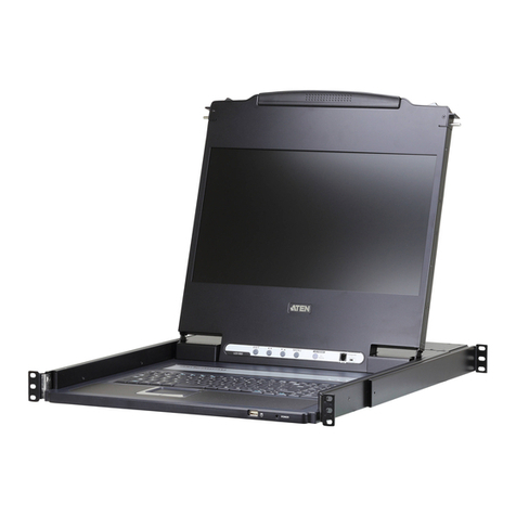
1
2
345
1
2
3
4
5
6
1
2
3
4
5
6
7
8
Press the Exit/Light pushbutton
for two seconds to turn the
LED light ON or Off. (Default: On)
EXIT ILIGHT
123 4
Package Contents
1 CL5800 Dual Rail LCD PS/2–USB
Console with Standard Rack Mount Kit
1 custom KVM cable
1 power cord
1 rmware upgrade cable
1 extension kit
1 user instructions
Support and Documentation Notice
All information, documentation, firmware,
software utilities, and specifications
contained in this package are subject to
change without prior notification by the
manufacturer.
To reduce the environmental impact of
our products, ATEN documentation and
software can be found online at
http://www.aten.com/download/
Technical Support
www.aten.com/support
Scan for more information
Product Page User Manual
Hardware Overview
Front View
Keyboard Module
LCD Module
Rear View
AInstallation
B
Standard Rack Mount
Dual Rail LCD Console
Quick Start Guide
CL5800
Operation
C
Opening the Console Closing the Console
Front-L Bracket Mount
CL5800
Power VGA
USB / PS/2
SPHD
2
5
1
4
6
3 3
Single Stage Installation
© Copyright 2023 ATEN®International Co. Ltd.
ATEN and the ATEN logo are registered trademarks of ATEN International Co., Ltd.
All rights reserved. All other trademarks are the property of their respective owners.
Part No. PAPE-1223-573G Released: 09/2023
Console LCD à double rail CL5800 www.aten.com
A
Description de l’appareil
Vue avant
1Poignée supérieure
2Module LCD
3Module clavier
4Poignée inférieure
5Voyant d’alimentation
6Loquet de libération LCD
7Supports de fi xation pour montage sur bâti
8Eclairage LED
Module clavier
1Loquet de libération du clavier
2Bouton de réinitialisation
3Voyants de verrouillage
4Clavier
5Pavé tactile
6Port USB
Module LCD
1Écran LCD
2Commandes LCD
3Bouton marche/arrêt de l'écran LCD
4Port de mise à jour du microprogramme
5Commutateur de mise à jour du
microprogramme
Vue arrière
1Prise d'alimentation
2Interrupteur
3Section de console externe
4Section des ports KVM
B
Installation
Montage en bâti standard
Un kit de montage sur bâti standard est fourni avec votre CL5800. Ce kit permet de
monter le commutateur sur un bâti, avec une profondeur de 52 à 85 cm.
Pour monter la console CL5800 sur bâti, procédez comme suit :
1. Alors que la première personne continue de maintenir en place la console CL5800,
la deuxième fait glisser les supports en L dans les supports de montage latéraux de la
CL5800 par l'arrière, jusqu'à ce que les brides des supports entrent en contact avec le
bâti, puis visse les supports en L sur le bâti.
2. Une fois les supports en L bien en place, serrez les vis des supports avant.
(En option) Support de montage avant en L
Pour assurer une posture à la fois confortable et sûre, installez les support avant en L qui
permettent d’avancer le rack vers l'avant et ainsi glisser l’unité davantage vers l'extérieur
et ainsi vous permettre d'incliner davantage l'écran LCD.
1. Fixez les supports de montage avant en L à l’avant du rack, en plaçant des vis dans les
languettes pour les maintenir en place.
Remarque : Les vis de rack ne sont pas fournies pour le montage de l’unité. Nous vous
recommandons d'utiliser deux vis M5 x P0,8 de chaque côté.
2. Demandez à une personne de positionner l'unité dans le rack et de la maintenir stable.
Demandez à la deuxième personne de visser les supports avant aux supports avant en L.
Remarque : Les vis de rack ne sont pas fournies pour le montage de l’unité. Nous vous
recommandons d'utiliser une vis M5 x P0,8 de chaque côté.
3. La deuxième personne doit, alors que la première personne maintient l'unité en place,
faire glisser les supports en L gauche et droit dans les supports de montage latéraux de
l'unité par l'arrière, en insérant quatre vis dans les supports pour les fixer en place.
4. Une fois les supports en L fixés, serrez toutes les vis. Assurez-vous de laisser un espace
d’au moins 5,1 cm de chaque côté pour permettre une ventilation adéquate et d’au
moins 12,7 cm à l’arrière pour le cordon d’alimentation et les câbles.
Installation en une étape
1Branchez une extrémité du connecteur SPHD du câble KVM sur le port KVM de la
console LCD.
2Branchez les connecteurs du clavier, du moniteur et de la souris du câble KVM sur les
ports correspondants de la section Console d'un commutateur KVM.
3Si vous installez une console externe, branchez votre clavier, votre moniteur et votre
souris sur leur port respectif sur la section Console de la console LCD. Les ports sont
identifi ables grâce un code de couleur et une icône spécifi que.
4Branchez le câble d'alimentation de la console CL5800 sur la prise d'alimentation de la
console LCD et sur une source d'alimentation.
5Allumez votre installation KVM.
6Allumez la console LCD.
C
Utilisation
Ouverture de la console
1. Tirez les loquets de libération pour dégager la console et tirez le panneau supérieur de
quelques centimètres vers vous.
2. En passant votre main en-dessous, tirez à fond le module clavier jusqu’à ce que vous
entendiez un clic indiquant qu’il est bien en place.
Fermeture de la console
1. Tirez vers vous les loquets de libération situés de chaque côté du clavier pour dégager
le module clavier puis faites légèrement glisser le module vers l’intérieur.
2. Tournez le module LCD complètement vers le bas puis tirez les loquets arrières pour
dégager le module LCD.
CL5800 Dual-Rail-LCD-Konsole www.aten.com
A
Hardwareübersicht
Vorderseitige Ansicht
1Griff oben
2LCD-Modul
3Tastaturmodul
4Griff unten
5LED-Betriebsanzeige
6Entriegelungstaste für LCD
7Arretierungen für Rack-Montage
8LED-Beleuchtung
Tastaturmodul
1Entriegelungstaste für Tastatur
2Reset-Taste
3Verriegelungs-LEDs
4Tastatur
5Touchpad
6USB-Port
LCD-Modul
1LCD-Display
2LCD-Bedienelemente
3Ein-/Ausschalter für LCD-Schirm
4Port zur Firmwareaktualisierung
5Schalter zur Firmwareaktualisierung
Rückseitige Ansicht
1Netzeingangsbuchse
2Netzschalter
3Externer Konsolabschnitt
4KVM-Portabschnitt
B
Installation
Standard-Rackmontage
Mit dem CL5800 wird ein Montagekit für ein Standard-Rack mitgeliefert. Mit diesem Kit
können Sie den Switch in ein Rack mit einer Tiefe von 52 -85 cm einbauen.
Um den CL5800 im Rack einzubauen, gehen Sie folgendermaßen vor:
1. Während die erste Person den CL5800 nach wie vor festhält, schiebt die zweite die
L-Schienen von hinten auf die seitlichen Montagerahmen des CL5800, bis der Flansch
den Rack berührt. Schrauben Sie die L-Schienen anschließend am Rack fest.
2. Nachdem Sie die L-Schienen befestigt haben, ziehen Sie auch die Schrauben an der
Vorderseite fest.
(Optional) Vordere L-Halterung
Um eine bequeme und sichere Körperhaltung einzunehmen, montieren Sie die vordere
L-Halterung, die eine Verlängerung an der Vorderseite des Gestells bietet, sodass das
Gerät weiter nach außen gleiten kann und Sie den LCD-Bildschirm somit weiter neigen
können.
1. Befestigen Sie die linke und rechte vordere L-Halterung an der Vorderseite des
Gestells, indem Sie die Schrauben in Halterungen einsetzen, um sie an Ort und Stelle
festzuschrauben.
Hinweis: Im Lieferumfang sind keine Gestellschrauben für die Montage der Einheit
erhalten. Wir empfehlen die Verwendung von zwei M5 x P0,8 Schrauben auf jeder
Seite.
2. Eine Person soll helfen, die Einheit am Gestell zu positionieren und zu fixieren. Lassen
Sie eine andere Person die vorderen Halterungen an die vordere L-Halterung schrauben.
Hinweis: Im Lieferumfang sind keine Gestellschrauben für die Montage der Einheit
erhalten. Wir empfehlen die Verwendung von einer M5 x P0,8 Schraube auf jeder Seite.
3. Während die erste Person die Einheit noch an Ort und Stelle hält, schiebt die zweite
Person die linken und rechten L-förmigen Halterungen von hinten in die seitlichen
Montagehalterungen der Einheit und schraubt die vier Schrauben in die Halterungen,
um sie zu sichern.
4. Nachdem die L-förmigen Halterungen befestigt sind, ziehen Sie alle Schrauben fest.
Lassen Sie für eine ordnungsgemäße Luftzirkulation an allen Seiten einen Freiraum
von mindestens 5,1 cm und mindestens 12,7 cm auf der Rückseite für die Netz- und
Anschlusskabel.
Einstufige Installation
1Verbinden Sie den SPHD-Stecker eines KVM-Kabels mit dem KVM-Port an der
LCD-Konsole.
2Verbinden Sie die Tastatur-, Monitor- und Mausanschlüsse des KVM-Kabels mit den
betreffenden Ports am Konsolabschnitt eines KVM-Switches.
3Wenn Sie eine externe Konsole anschließen möchten, verbinden Sie Tastatur, Monitor
und Maus mit den zugehörigen Anschlüssen im Konsolabschnitt der LCD-Konsole. Die
Buchsen sind farblich und mit einem Symbol gekennzeichnet.
4Verbinden Sie das Netzkabel des CL5800 mit der Stromeingangsbuchse der
LCD-Konsole und einer Stromquelle.
5Schalten Sie die KVM-Installation ein.
6Schalten Sie die LCD-Konsole ein.
C
Bedienung
Konsole öffnen
1. Ziehen Sie an den Griffen, um die Konsole zu entriegeln, und ziehen Sie das Gerät an
der Vorderseite einige Zentimeter zu sich heran.
2. Greifen Sie unter das Gerät, und ziehen Sie das Tastaturmodul ganz heraus, bis es
einrastet.
Konsole schließen
1. Ziehen Sie die Entriegelungsgriffe, die sich auf jeder Seite der Tastatur befi nden,
zu sich, um das Tastaturmodul freizugeben. Anschließend schieben Sie das Modul
vorsichtig hinein.
2. Klappen Sie das LCD-Modul ganz zu, und ziehen Sie an den rückseitigen Griffen, um es
zu entriegeln.
Consola LCD Dual Rail CL5800 www.aten.com
A
Reseña del hardware
Vista frontal
1Mango superior
2Módulo LCD
3Módulo de teclado
4Mango inferior
5Indicador LED de alimentación
6Botón de desbloqueo LCD
7Muescas para montaje en rack
8Iluminacion LED
Módulo de teclado
1Botón de desbloqueo del teclado
2Tecla de reseteo
3Indicadores LED de bloqueo
4Teclado
5Panel táctil
6Puerto USB
Módulo LCD
1Pantalla LCD
2Controles LCD
3Botón LCD encendido/apagado
4Puerto para actualizaciones del firmware
5Conmutador para actualizar el firmware
Vista posterior
1Entrada de alimentación
2Interruptor de alimentación
3Sección de consola externa
4Sección de puertos KVM
B
Instalación
Soporte para estantería estándar
Con el CL5800 viene un kit de montaje en rack estándar. Con este kit puede montarlo en
un rack con una profundidad entre 52 y 85 cm.
Para montar la CL5800 en el rack, haga lo siguiente:
1. Mientras la primera persona sigue aguantando la CL5800, la segunda desliza los raíles
en L sobre la CL5800 desde la parte trasera hasta que la pestaña del soporte haga
contacto con el rack y luego atornilla los raíles en L al rack.
2. Cuando tenga los raíles en L atornillados, apriete los tornillos frontales de los raíles.
(Opcional) Montaje de soporte en L delantero
Para disfrutar de una postura cómoda y segura, instale los soportes en L delanteros que
proporcionan una extensión en la parte delantera del bastidor, para hacer que la unidad se
pueda deslizar hacia fuera un poco más, permitiéndole inclinar la pantalla LCD aún más.
1. Acople los soportes en L delanteros izquierdo y derecho a la parte delantera de la
estantería, colocando tornillos en las pestañas para fijarlos en su posición.
Nota: No se suministran tornillos de estantería para montar la unidad. Recomendamos
que utilice dos tornillos M5 x P0,8 a cada lado.
2. Una persona debe colocar la unidad en la estantería y sujetarla de forma estable.
Otra segunda persona debe atornillar los soportes delanteros al soporte en L delantero.
Nota: No se suministran tornillos de estantería para montar la unidad. Recomendamos
que utilice un tornillo M5 x P0,8 a cada lado.
3. Mientras la primera persona mantiene la unidad en su lugar, la segunda persona
deslizará los soportes en forma de L izquierdo y derecho hacia los soportes de montaje
del lado de la unidad desde la parte posterior, instalando cuatro tornillos en los soportes
para fijarlos en su posición.
4. Después de haber fijado los soportes en forma de L, apriete todos los tornillos. Deje
al menos 5,1 cm a cada lado para una ventilación adecuada y al menos 12,7 cm en la
parte posterior para que el cable de alimentación se pueda mover holgadamente.
Instalación de una sola etapa
1Enchufe el conector SPHD de un cable KVM al puerto KVM de la consola LCD.
2Enchufe los conectores para teclado, monitor y ratón del cable KVM a los puertos
respectivos de la sección de consola de un conmutador KVM.
3Si instala una consola externa, enchufe el teclado, el monitor y el ratón a los puertos
respectivos de la sección de consola del equipo. Los puertos llevan el código de color
estándar, además de un icono para su identifi cación.
4Enchufe el cable de alimentación de la CL5800 a la entrada de alimentación de la
consola LCD y a una fuente de alimentación.
5Encienda toda la instalación KVM.
6Encienda la consola LCD.
C
Funcionamiento
Abrir la consola
1. Tire de los mangos de desbloqueo para liberar la consola y luego estire de la parte
anterior para acercar la unidad algunos centímetros hacia Usted.
2. Coloque la mano debajo del módulo de teclado y estírelo completamente hacia
adelante hasta que encaje y quede asegurado.
Cerrar la consola
1. Tire los mangos de desbloqueo ubicados en cada lado del teclado hacia Usted para
desbloquear el módulo de teclado y luego deslice el módulo cuidadosamente hacia
dentro.
2. Cierre el módulo LCD completamente y luego estire de los mangos posteriores para
desbloquear el módulo LCD.
Postazione CL5800 LCD a doppio binario www.aten.com
A
Panoramica hardware
Visione anteriore
1Maniglia superiore
2Modulo LCD
3Modulo tastiera
4Maniglia inferiore
5LED d’alimentazione
6Fermo di sganciamento del monitor LCD
7Linguette per il montaggio in rack
8Illuminazione LED
Modulo tastiera
1Fermo di sganciamento della tastiera
2Pulsante Ripristina
3LED di blocco
4Tastiera
5Tavoletta tattile
6Porta USB
Modulo LCD
1Display a cristalli liquidi
2Comandi LCD
3Pulsante di accensione/spegnimento
dello schermo
4Porta per l’aggiornamento del firmware
5Commutatore per l’aggiornamento del
firmware
Visione posteriore
1Presa per l’alimentazione
2Interruttore di alimentazione
3Sezione della console esterna
4Sezione della porta KVM
B
Installazione
Montaggio standard su rack
CL5800 è dotato di un kit standard per il montaggio in rack. Il kit consente di montare lo
switch in rack con una profondità di 52-85cm.
Per montare in rack il CL5800, procedere come segue:
1. Mentre la prima persona continua a tenere in posizione il CL5800, la seconda fa
scivolare le staffe a L nei supporti laterali di montaggio, partendo dal retro, fino a
quando non sono a stretto contatto con il rack e poi avvita le staffe a L al rack.
2. Una volta fissati i supporti a L, stringere le viti dei supporti anteriori.
(Opzionale) Montaggio della staffa anteriore a L
Per avere una postura comoda e corretta, installare le staffe anteriori a L che consentono
di estendere la parte anteriore del rack consentendo all’unità di scivolare ulteriormente e
consentendo di inclinare maggiormente lo schermo LCD.
1. Fissare le staffe anteriori a L, sia la destra che la sinistra, alla parte anteriore del rack,
inserendo delle viti nelle linguetteper fissarle correttamente.
Nota: Non vengono fornite le viti da rack per il montaggio di questa unità. Si consiglia
di utilizzare due viti M5 x P0,8 su ciascun lato.
2. Farsi aiutare da un’altra persona a posizionare l’unità nel rack e a tenerla ferma. La
seconda persona deve avvitare le staffe anteriori alla staffa a L anteriore.
Nota: Non vengono fornite le viti da rack per il montaggio di questa unità. Si consiglia
di utilizzare una vite M5 x P0,8 su ciascun lato.
3. Mentre una persona mantiene l’unità in posizione, la seconda persona fa scivolare
dal retro le staffe a L, sia la destra che la sinistra, nelle staffe di montaggio laterali
dell’unità, stringendo quattro viti nelle staffe per fissarle bene.
4. Dopo aver fissato le staffe a forma di L, stringere tutte le viti. Lasciare uno spazio di
almeno 5,1 cm su entrambi i lati per garantire un'adeguata areazione e uno spazio di
almeno 12,7 cm sul retro per contenere il cavo di alimentazione e lo spazio necessario
intorno.
Installazione a fase singola
1PCollegare l’estremità con il connettore SPHD di un cavo KVM alla porta KVM della
console LCD.
2Inserire i connettori della tastiera, del monitor e del mouse del cavo KVM nelle loro
rispettive porte sulla sezione della console dello switch KVM.
3In caso di installazione di una console esterna, collegare tastiera, mouse e monitor
nelle rispettive porte sulla sezione Console della console LCD. Le porte seguono un
codice a colori e sono contrassegnate da un’icona, per essere identificate facilmente.
4Inserire la spina del cavo dell’alimentazione del CL5800 nella presa dell’alimentazione
della console LCD e in una presa d’alimentazione di rete.
5Accendere l’installazione KVM.
6Accendere la Console LCD.
C
Funzionamento
Apertura della console
1. Per sganciare la console, sollevare i fermi di sganciamento e tirare a sé il pannello
superiore di pochi centimetri.
2. Raggiungere e tirare il modulo della tastiera fino a quando non scatta con un clic al suo
posto.
Chiusura della console
1. Per sganciare il modulo della tastiera, tirare a sé i fermi di sganciamento situati su ogni
lato della stessa e poi farlo scivolare leggermente verso l’interno.
2. Per sganciare il modulo LCD, ruotarlo il verso il basso e poi tirare i fermi di sganciamento
posteriori.
CL5800 Консоль Dual Rail с ЖК-дисплеем www.aten.com
А
Обзор оборудования
Вид спереди
1 Верхняя ручка
2 Модуль ЖК-дисплея
3 Клавиатурный модуль
4 Нижняя ручка
5 Индикатор питания
6 Фиксатор ЖК-дисплея
7 Кронштейны для монтажа в стойку
8 Светодиодная подсветка
Клавиатурный модуль
1 Фиксатор клавиатуры
2 Кнопка сброса настроек
3 Индикаторы блокировки
4 Клавиатура
5 Сенсорная панель
6 USB-разъем
Модуль ЖК-дисплея
1 ЖК-дисплей
2 Кнопки управления ЖК-дисплеем
3 Кнопка включения/отключения
ЖК-дисплея
4 Разъем для обновления прошивки
5 Переключатель обновления
прошивки
Вид сзади
1 Разъем питания
2 Выключатель питания
3 Секция внешней консоли
4 Блок KVM-портов
B
Установка
Стандартный монтаж в стойку
В комплектацию CL5800 входит стандартный набор для монтажа в стойку. С его
помощью переключатель можно установить в стойку глубиной 52–85 см.
Процедура монтажа CL5800 в стойку:
1. Зафиксируйте CL5800 в нужном положении силами одного человека. Поручите
второму задвинуть левый и правый Г-образные кронштейны в боковые посадочные
места на CL5800, действуя с задней стороны устройства. Когда Г-образные
кронштейны встанут вровень со стойкой, закрепите их с помощью винтов.
2. После крепления L-образных кронштейнов затяните винты передних кронштейнов.
(По выбору) Фронтальный монтаж Г-образных кронштейнов
Чтобы создать эргономичные и безопасные условия работы стоя или сидя,
установите фронтальные Г-образные кронштейны, которые удлиняют плечо в
передней части стойки. В результате устройство можно будет выдвинуть еще
дальше и наклонить ЖК-монитор под более удобным углом.
1. Закрепите левый и правый фронтальные Г-образные кронштейны на передней
части стойки, вставив крепежные винты в отверстия для фиксации.
Примечание. В комплектацию устройства не входят крепежные винты для
фиксации в стойке. Рекомендуем использовать с каждой стороны по два винта
M5 x P0,8.
2. Работу выполняют вдвоем. Один человек размещает устройство в стойке и крепко
удерживает его в этом положении. Второй привинчивает к передней части стойки
фронтальные Г-образные кронштейны.
Примечание. В комплектацию устройства не входят крепежные винты для
фиксации в стойке. Рекомендуем использовать с каждой стороны по одному
винту M5 x P0,8.
3. Зафиксируйте устройство в нужном положении силами одного человека.
Поручите второму задвинуть левый и правый Г-образные кронштейны в
боковые посадочные места на устройстве, действуя с его задней стороны.
Затем вставьте в эти кронштейны четыре винта для дальнейшей фиксации.
4. После фиксации Г-образных кронштейнов затяните все винты. Оставьте зазор
по меньшей мере 5,1 см с каждой стороны для надлежащей вентиляции и по
меньшей мере 12,7 см с задней стороны, чтобы уложить шнур питания и кабели.
Одноэтапная установка
1 Подключите кабель KVM к разъему KVM на консоли с ЖК-дисплеем так, чтобы
штекер SPHD вошел в консоль.
2 Подключите штекеры кабеля KVM, передающие сигнал на клавиатуру, мышь и
монитор, к соответствующим разъемам консольного блока KVM-переключателя.
3 В случае установки внешней консоли подключите клавиатуру, мышь и монитор
к соответствующим разъемам консольного блока на консоли с ЖК-дисплеем.
Разъемы легко различить благодаря цветовой кодировке и пиктограммам.
4 Подключите кабель питания CL5800 к разъему питания на консоли с ЖК-дисплеем
и к источнику питания.
5 Подайте питание на систему KVM в сборе.
6 Включите консоль с ЖК-дисплеем.
C
Эксплуатация
Открытие консоли
1. Потяните фиксаторы, чтобы освободить консоль, затем вытяните верхнюю
панель к себе на несколько сантиметров.
2. Нащупайте клавиатурный модуль под ней, затем вытяните его целиком до
щелчка, чтобы он встал на место.
Закрытие консоли
1. Потяните к себе фиксаторы по бокам клавиатуры, чтобы освободить
клавиатурный модуль, затем задвиньте его внутрь, не прилагая большого усилия.
2. Поверните модуль ЖК-дисплея вниз до упора, затем потяните задние
фиксаторы, чтобы освободить его.
CL5800 Dual Rail LCD Console www.aten.com
A
Hardware Overview
Front View
1upper handle
2LCD module
3keyboard module
4lower handle
5power LED
6LCD release catch
7rack mounting tabs
8LED illumination light
Keyboard Module
1keyboard release catch
2reset button
3lock LEDs
4keyboard
5touch pad
6USB port
LCD Module
1LCD display
2LCD controls
3LCD on / off button
4firmware upgrade port
5firmware upgrade switch
Rear View
1power socket
2power switch
3external console section
4KVM port section
B
Installation
Standard Rack Mount
A standard rack mount kit is provided with your CL5800. The kit enables the switch to be
mounted in rack with a depth of 52-85cm.
To rack mount the CL5800, do the following:
1. While the first person still holds the CL5800 in place, the second person slides the L
brackets into the CL5800's side mounting brackets from the rear until the bracket
flanges contact the rack, then screws the L brackets to the rack.
2. After the L brackets have been secured, tighten the front bracket screws.
(Optional) Front-L Bracket Mount
To have a comfortable and safe posture, install the Front-L brackets which provide an
extension at the front of the rack to help the unit slide further out and thus allowing you
to tilt the LCD screen more.
1. Attach the left and right Front-L brackets to the front of the rack, placing screws in the
tabs to secure them in place.
Note: Rack screws are not provided to mount the unit. We recommend that you use
two M5 x P0.8 screws on each side.
2. Have one person position the unit in the rack and hold it steady. Have the second
person screw the front brackets to the Front-L bracket.
Note: Rack screws are. not provided to mount the unit. We recommend that you use
one M5 x P0.8 screws on each side.
3. While the first person still holds the unit in place, the second person slides the left and
right L-shaped brackets into the unit’s side mounting brackets from the rear, installing
four screws in the brackets to secure them in place.
4. After the L-shaped brackets are secured, tighten all the screws. Allow at least 5.1 cm
on each side for proper ventilation, and at least 12.7 cm at the back for the power cord
and cable clearance.
Single Stage Installation
1Plug the SPHD connector end of a KVM cable into the LCD Console's KVM port.
2Plug the keyboard, monitor, and mouse connectors of the KVM cable into their
respective ports on the Console Section of a KVM switch.
3If you are installing an external console, plug your keyboard, monitor, and mouse into
their respective ports on the Console Section of the LCD Console. The ports are color
coded and marked with an icon for easy identification.
4Plug the CL5800’s power cord into the LCD Console's power socket and into a power
source.
5Power up your KVM installation.
6Turn on the power to LCD Console.
C
Operation
Opening the Console
1. Pull the release catches to release the console, and pull the top panel a few centimeters
toward you.
2. Reach underneath and pull the keyboard module all the way out until it clicks into
place.
Closing the Console
1. Pull the release catches located on either side of the keyboard toward you to release
the keyboard module, then slide the module slightly in.
2. Rotate the LCD module all the way down, then pull the rear catches to release the LCD
module.
1
2
345
1
2
3
4
5
6
1
2
3
4
5
6
7
8
Press the Exit/Light pushbutton
for two seconds to turn the
LED light ON or Off. (Default: On)
EXIT ILIGHT
123 4
Package Contents
1 CL5800 Dual Rail LCD PS/2–USB
Console with Standard Rack Mount Kit
1 custom KVM cable
1 power cord
1 rmware upgrade cable
1 extension kit
1 user instructions
Support and Documentation Notice
All information, documentation, firmware,
software utilities, and specifications
contained in this package are subject to
change without prior notification by the
manufacturer.
To reduce the environmental impact of
our products, ATEN documentation and
software can be found online at
http://www.aten.com/download/
Technical Support
www.aten.com/support
Scan for more information
Product Page User Manual
Hardware Overview
Front View
Keyboard Module
LCD Module
Rear View
AInstallation
B
Standard Rack Mount
Dual Rail LCD Console
Quick Start Guide
CL5800
Operation
C
Opening the Console Closing the Console
Front-L Bracket Mount
CL5800
Power VGA
USB / PS/2
SPHD
2
5
1
4
6
3 3
Single Stage Installation
© Copyright 2023 ATEN®International Co. Ltd.
ATEN and the ATEN logo are registered trademarks of ATEN International Co., Ltd.
All rights reserved. All other trademarks are the property of their respective owners.
Part No. PAPE-1223-573G Released: 09/2023
Console LCD à double rail CL5800 www.aten.com
A
Description de l’appareil
Vue avant
1Poignée supérieure
2Module LCD
3Module clavier
4Poignée inférieure
5Voyant d’alimentation
6Loquet de libération LCD
7Supports de fi xation pour montage sur bâti
8Eclairage LED
Module clavier
1Loquet de libération du clavier
2Bouton de réinitialisation
3Voyants de verrouillage
4Clavier
5Pavé tactile
6Port USB
Module LCD
1Écran LCD
2Commandes LCD
3Bouton marche/arrêt de l'écran LCD
4Port de mise à jour du microprogramme
5Commutateur de mise à jour du
microprogramme
Vue arrière
1Prise d'alimentation
2Interrupteur
3Section de console externe
4Section des ports KVM
B
Installation
Montage en bâti standard
Un kit de montage sur bâti standard est fourni avec votre CL5800. Ce kit permet de
monter le commutateur sur un bâti, avec une profondeur de 52 à 85 cm.
Pour monter la console CL5800 sur bâti, procédez comme suit :
1. Alors que la première personne continue de maintenir en place la console CL5800,
la deuxième fait glisser les supports en L dans les supports de montage latéraux de la
CL5800 par l'arrière, jusqu'à ce que les brides des supports entrent en contact avec le
bâti, puis visse les supports en L sur le bâti.
2. Une fois les supports en L bien en place, serrez les vis des supports avant.
(En option) Support de montage avant en L
Pour assurer une posture à la fois confortable et sûre, installez les support avant en L qui
permettent d’avancer le rack vers l'avant et ainsi glisser l’unité davantage vers l'extérieur
et ainsi vous permettre d'incliner davantage l'écran LCD.
1. Fixez les supports de montage avant en L à l’avant du rack, en plaçant des vis dans les
languettes pour les maintenir en place.
Remarque : Les vis de rack ne sont pas fournies pour le montage de l’unité. Nous vous
recommandons d'utiliser deux vis M5 x P0,8 de chaque côté.
2. Demandez à une personne de positionner l'unité dans le rack et de la maintenir stable.
Demandez à la deuxième personne de visser les supports avant aux supports avant en L.
Remarque : Les vis de rack ne sont pas fournies pour le montage de l’unité. Nous vous
recommandons d'utiliser une vis M5 x P0,8 de chaque côté.
3. La deuxième personne doit, alors que la première personne maintient l'unité en place,
faire glisser les supports en L gauche et droit dans les supports de montage latéraux de
l'unité par l'arrière, en insérant quatre vis dans les supports pour les fixer en place.
4. Une fois les supports en L fixés, serrez toutes les vis. Assurez-vous de laisser un espace
d’au moins 5,1 cm de chaque côté pour permettre une ventilation adéquate et d’au
moins 12,7 cm à l’arrière pour le cordon d’alimentation et les câbles.
Installation en une étape
1Branchez une extrémité du connecteur SPHD du câble KVM sur le port KVM de la
console LCD.
2Branchez les connecteurs du clavier, du moniteur et de la souris du câble KVM sur les
ports correspondants de la section Console d'un commutateur KVM.
3Si vous installez une console externe, branchez votre clavier, votre moniteur et votre
souris sur leur port respectif sur la section Console de la console LCD. Les ports sont
identifi ables grâce un code de couleur et une icône spécifi que.
4Branchez le câble d'alimentation de la console CL5800 sur la prise d'alimentation de la
console LCD et sur une source d'alimentation.
5Allumez votre installation KVM.
6Allumez la console LCD.
C
Utilisation
Ouverture de la console
1. Tirez les loquets de libération pour dégager la console et tirez le panneau supérieur de
quelques centimètres vers vous.
2. En passant votre main en-dessous, tirez à fond le module clavier jusqu’à ce que vous
entendiez un clic indiquant qu’il est bien en place.
Fermeture de la console
1. Tirez vers vous les loquets de libération situés de chaque côté du clavier pour dégager
le module clavier puis faites légèrement glisser le module vers l’intérieur.
2. Tournez le module LCD complètement vers le bas puis tirez les loquets arrières pour
dégager le module LCD.
CL5800 Dual-Rail-LCD-Konsole www.aten.com
A
Hardwareübersicht
Vorderseitige Ansicht
1Griff oben
2LCD-Modul
3Tastaturmodul
4Griff unten
5LED-Betriebsanzeige
6Entriegelungstaste für LCD
7Arretierungen für Rack-Montage
8LED-Beleuchtung
Tastaturmodul
1Entriegelungstaste für Tastatur
2Reset-Taste
3Verriegelungs-LEDs
4Tastatur
5Touchpad
6USB-Port
LCD-Modul
1LCD-Display
2LCD-Bedienelemente
3Ein-/Ausschalter für LCD-Schirm
4Port zur Firmwareaktualisierung
5Schalter zur Firmwareaktualisierung
Rückseitige Ansicht
1Netzeingangsbuchse
2Netzschalter
3Externer Konsolabschnitt
4KVM-Portabschnitt
B
Installation
Standard-Rackmontage
Mit dem CL5800 wird ein Montagekit für ein Standard-Rack mitgeliefert. Mit diesem Kit
können Sie den Switch in ein Rack mit einer Tiefe von 52 -85 cm einbauen.
Um den CL5800 im Rack einzubauen, gehen Sie folgendermaßen vor:
1. Während die erste Person den CL5800 nach wie vor festhält, schiebt die zweite die
L-Schienen von hinten auf die seitlichen Montagerahmen des CL5800, bis der Flansch
den Rack berührt. Schrauben Sie die L-Schienen anschließend am Rack fest.
2. Nachdem Sie die L-Schienen befestigt haben, ziehen Sie auch die Schrauben an der
Vorderseite fest.
(Optional) Vordere L-Halterung
Um eine bequeme und sichere Körperhaltung einzunehmen, montieren Sie die vordere
L-Halterung, die eine Verlängerung an der Vorderseite des Gestells bietet, sodass das
Gerät weiter nach außen gleiten kann und Sie den LCD-Bildschirm somit weiter neigen
können.
1. Befestigen Sie die linke und rechte vordere L-Halterung an der Vorderseite des
Gestells, indem Sie die Schrauben in Halterungen einsetzen, um sie an Ort und Stelle
festzuschrauben.
Hinweis: Im Lieferumfang sind keine Gestellschrauben für die Montage der Einheit
erhalten. Wir empfehlen die Verwendung von zwei M5 x P0,8 Schrauben auf jeder
Seite.
2. Eine Person soll helfen, die Einheit am Gestell zu positionieren und zu fixieren. Lassen
Sie eine andere Person die vorderen Halterungen an die vordere L-Halterung schrauben.
Hinweis: Im Lieferumfang sind keine Gestellschrauben für die Montage der Einheit
erhalten. Wir empfehlen die Verwendung von einer M5 x P0,8 Schraube auf jeder Seite.
3. Während die erste Person die Einheit noch an Ort und Stelle hält, schiebt die zweite
Person die linken und rechten L-förmigen Halterungen von hinten in die seitlichen
Montagehalterungen der Einheit und schraubt die vier Schrauben in die Halterungen,
um sie zu sichern.
4. Nachdem die L-förmigen Halterungen befestigt sind, ziehen Sie alle Schrauben fest.
Lassen Sie für eine ordnungsgemäße Luftzirkulation an allen Seiten einen Freiraum
von mindestens 5,1 cm und mindestens 12,7 cm auf der Rückseite für die Netz- und
Anschlusskabel.
Einstufige Installation
1Verbinden Sie den SPHD-Stecker eines KVM-Kabels mit dem KVM-Port an der
LCD-Konsole.
2Verbinden Sie die Tastatur-, Monitor- und Mausanschlüsse des KVM-Kabels mit den
betreffenden Ports am Konsolabschnitt eines KVM-Switches.
3Wenn Sie eine externe Konsole anschließen möchten, verbinden Sie Tastatur, Monitor
und Maus mit den zugehörigen Anschlüssen im Konsolabschnitt der LCD-Konsole. Die
Buchsen sind farblich und mit einem Symbol gekennzeichnet.
4Verbinden Sie das Netzkabel des CL5800 mit der Stromeingangsbuchse der
LCD-Konsole und einer Stromquelle.
5Schalten Sie die KVM-Installation ein.
6Schalten Sie die LCD-Konsole ein.
C
Bedienung
Konsole öffnen
1. Ziehen Sie an den Griffen, um die Konsole zu entriegeln, und ziehen Sie das Gerät an
der Vorderseite einige Zentimeter zu sich heran.
2. Greifen Sie unter das Gerät, und ziehen Sie das Tastaturmodul ganz heraus, bis es
einrastet.
Konsole schließen
1. Ziehen Sie die Entriegelungsgriffe, die sich auf jeder Seite der Tastatur befi nden,
zu sich, um das Tastaturmodul freizugeben. Anschließend schieben Sie das Modul
vorsichtig hinein.
2. Klappen Sie das LCD-Modul ganz zu, und ziehen Sie an den rückseitigen Griffen, um es
zu entriegeln.
Consola LCD Dual Rail CL5800 www.aten.com
A
Reseña del hardware
Vista frontal
1Mango superior
2Módulo LCD
3Módulo de teclado
4Mango inferior
5Indicador LED de alimentación
6Botón de desbloqueo LCD
7Muescas para montaje en rack
8Iluminacion LED
Módulo de teclado
1Botón de desbloqueo del teclado
2Tecla de reseteo
3Indicadores LED de bloqueo
4Teclado
5Panel táctil
6Puerto USB
Módulo LCD
1Pantalla LCD
2Controles LCD
3Botón LCD encendido/apagado
4Puerto para actualizaciones del firmware
5Conmutador para actualizar el firmware
Vista posterior
1Entrada de alimentación
2Interruptor de alimentación
3Sección de consola externa
4Sección de puertos KVM
B
Instalación
Soporte para estantería estándar
Con el CL5800 viene un kit de montaje en rack estándar. Con este kit puede montarlo en
un rack con una profundidad entre 52 y 85 cm.
Para montar la CL5800 en el rack, haga lo siguiente:
1. Mientras la primera persona sigue aguantando la CL5800, la segunda desliza los raíles
en L sobre la CL5800 desde la parte trasera hasta que la pestaña del soporte haga
contacto con el rack y luego atornilla los raíles en L al rack.
2. Cuando tenga los raíles en L atornillados, apriete los tornillos frontales de los raíles.
(Opcional) Montaje de soporte en L delantero
Para disfrutar de una postura cómoda y segura, instale los soportes en L delanteros que
proporcionan una extensión en la parte delantera del bastidor, para hacer que la unidad se
pueda deslizar hacia fuera un poco más, permitiéndole inclinar la pantalla LCD aún más.
1. Acople los soportes en L delanteros izquierdo y derecho a la parte delantera de la
estantería, colocando tornillos en las pestañas para fijarlos en su posición.
Nota: No se suministran tornillos de estantería para montar la unidad. Recomendamos
que utilice dos tornillos M5 x P0,8 a cada lado.
2. Una persona debe colocar la unidad en la estantería y sujetarla de forma estable.
Otra segunda persona debe atornillar los soportes delanteros al soporte en L delantero.
Nota: No se suministran tornillos de estantería para montar la unidad. Recomendamos
que utilice un tornillo M5 x P0,8 a cada lado.
3. Mientras la primera persona mantiene la unidad en su lugar, la segunda persona
deslizará los soportes en forma de L izquierdo y derecho hacia los soportes de montaje
del lado de la unidad desde la parte posterior, instalando cuatro tornillos en los soportes
para fijarlos en su posición.
4. Después de haber fijado los soportes en forma de L, apriete todos los tornillos. Deje
al menos 5,1 cm a cada lado para una ventilación adecuada y al menos 12,7 cm en la
parte posterior para que el cable de alimentación se pueda mover holgadamente.
Instalación de una sola etapa
1Enchufe el conector SPHD de un cable KVM al puerto KVM de la consola LCD.
2Enchufe los conectores para teclado, monitor y ratón del cable KVM a los puertos
respectivos de la sección de consola de un conmutador KVM.
3Si instala una consola externa, enchufe el teclado, el monitor y el ratón a los puertos
respectivos de la sección de consola del equipo. Los puertos llevan el código de color
estándar, además de un icono para su identifi cación.
4Enchufe el cable de alimentación de la CL5800 a la entrada de alimentación de la
consola LCD y a una fuente de alimentación.
5Encienda toda la instalación KVM.
6Encienda la consola LCD.
C
Funcionamiento
Abrir la consola
1. Tire de los mangos de desbloqueo para liberar la consola y luego estire de la parte
anterior para acercar la unidad algunos centímetros hacia Usted.
2. Coloque la mano debajo del módulo de teclado y estírelo completamente hacia
adelante hasta que encaje y quede asegurado.
Cerrar la consola
1. Tire los mangos de desbloqueo ubicados en cada lado del teclado hacia Usted para
desbloquear el módulo de teclado y luego deslice el módulo cuidadosamente hacia
dentro.
2. Cierre el módulo LCD completamente y luego estire de los mangos posteriores para
desbloquear el módulo LCD.
Postazione CL5800 LCD a doppio binario www.aten.com
A
Panoramica hardware
Visione anteriore
1Maniglia superiore
2Modulo LCD
3Modulo tastiera
4Maniglia inferiore
5LED d’alimentazione
6Fermo di sganciamento del monitor LCD
7Linguette per il montaggio in rack
8Illuminazione LED
Modulo tastiera
1Fermo di sganciamento della tastiera
2Pulsante Ripristina
3LED di blocco
4Tastiera
5Tavoletta tattile
6Porta USB
Modulo LCD
1Display a cristalli liquidi
2Comandi LCD
3Pulsante di accensione/spegnimento
dello schermo
4Porta per l’aggiornamento del firmware
5Commutatore per l’aggiornamento del
firmware
Visione posteriore
1Presa per l’alimentazione
2Interruttore di alimentazione
3Sezione della console esterna
4Sezione della porta KVM
B
Installazione
Montaggio standard su rack
CL5800 è dotato di un kit standard per il montaggio in rack. Il kit consente di montare lo
switch in rack con una profondità di 52-85cm.
Per montare in rack il CL5800, procedere come segue:
1. Mentre la prima persona continua a tenere in posizione il CL5800, la seconda fa
scivolare le staffe a L nei supporti laterali di montaggio, partendo dal retro, fino a
quando non sono a stretto contatto con il rack e poi avvita le staffe a L al rack.
2. Una volta fissati i supporti a L, stringere le viti dei supporti anteriori.
(Opzionale) Montaggio della staffa anteriore a L
Per avere una postura comoda e corretta, installare le staffe anteriori a L che consentono
di estendere la parte anteriore del rack consentendo all’unità di scivolare ulteriormente e
consentendo di inclinare maggiormente lo schermo LCD.
1. Fissare le staffe anteriori a L, sia la destra che la sinistra, alla parte anteriore del rack,
inserendo delle viti nelle linguetteper fissarle correttamente.
Nota: Non vengono fornite le viti da rack per il montaggio di questa unità. Si consiglia
di utilizzare due viti M5 x P0,8 su ciascun lato.
2. Farsi aiutare da un’altra persona a posizionare l’unità nel rack e a tenerla ferma. La
seconda persona deve avvitare le staffe anteriori alla staffa a L anteriore.
Nota: Non vengono fornite le viti da rack per il montaggio di questa unità. Si consiglia
di utilizzare una vite M5 x P0,8 su ciascun lato.
3. Mentre una persona mantiene l’unità in posizione, la seconda persona fa scivolare
dal retro le staffe a L, sia la destra che la sinistra, nelle staffe di montaggio laterali
dell’unità, stringendo quattro viti nelle staffe per fissarle bene.
4. Dopo aver fissato le staffe a forma di L, stringere tutte le viti. Lasciare uno spazio di
almeno 5,1 cm su entrambi i lati per garantire un'adeguata areazione e uno spazio di
almeno 12,7 cm sul retro per contenere il cavo di alimentazione e lo spazio necessario
intorno.
Installazione a fase singola
1PCollegare l’estremità con il connettore SPHD di un cavo KVM alla porta KVM della
console LCD.
2Inserire i connettori della tastiera, del monitor e del mouse del cavo KVM nelle loro
rispettive porte sulla sezione della console dello switch KVM.
3In caso di installazione di una console esterna, collegare tastiera, mouse e monitor
nelle rispettive porte sulla sezione Console della console LCD. Le porte seguono un
codice a colori e sono contrassegnate da un’icona, per essere identificate facilmente.
4Inserire la spina del cavo dell’alimentazione del CL5800 nella presa dell’alimentazione
della console LCD e in una presa d’alimentazione di rete.
5Accendere l’installazione KVM.
6Accendere la Console LCD.
C
Funzionamento
Apertura della console
1. Per sganciare la console, sollevare i fermi di sganciamento e tirare a sé il pannello
superiore di pochi centimetri.
2. Raggiungere e tirare il modulo della tastiera fino a quando non scatta con un clic al suo
posto.
Chiusura della console
1. Per sganciare il modulo della tastiera, tirare a sé i fermi di sganciamento situati su ogni
lato della stessa e poi farlo scivolare leggermente verso l’interno.
2. Per sganciare il modulo LCD, ruotarlo il verso il basso e poi tirare i fermi di sganciamento
posteriori.
CL5800 Консоль Dual Rail с ЖК-дисплеем www.aten.com
А
Обзор оборудования
Вид спереди
1 Верхняя ручка
2 Модуль ЖК-дисплея
3 Клавиатурный модуль
4 Нижняя ручка
5 Индикатор питания
6 Фиксатор ЖК-дисплея
7 Кронштейны для монтажа в стойку
8 Светодиодная подсветка
Клавиатурный модуль
1 Фиксатор клавиатуры
2 Кнопка сброса настроек
3 Индикаторы блокировки
4 Клавиатура
5 Сенсорная панель
6 USB-разъем
Модуль ЖК-дисплея
1 ЖК-дисплей
2 Кнопки управления ЖК-дисплеем
3 Кнопка включения/отключения
ЖК-дисплея
4 Разъем для обновления прошивки
5 Переключатель обновления
прошивки
Вид сзади
1 Разъем питания
2 Выключатель питания
3 Секция внешней консоли
4 Блок KVM-портов
B
Установка
Стандартный монтаж в стойку
В комплектацию CL5800 входит стандартный набор для монтажа в стойку. С его
помощью переключатель можно установить в стойку глубиной 52–85 см.
Процедура монтажа CL5800 в стойку:
1. Зафиксируйте CL5800 в нужном положении силами одного человека. Поручите
второму задвинуть левый и правый Г-образные кронштейны в боковые посадочные
места на CL5800, действуя с задней стороны устройства. Когда Г-образные
кронштейны встанут вровень со стойкой, закрепите их с помощью винтов.
2. После крепления L-образных кронштейнов затяните винты передних кронштейнов.
(По выбору) Фронтальный монтаж Г-образных кронштейнов
Чтобы создать эргономичные и безопасные условия работы стоя или сидя,
установите фронтальные Г-образные кронштейны, которые удлиняют плечо в
передней части стойки. В результате устройство можно будет выдвинуть еще
дальше и наклонить ЖК-монитор под более удобным углом.
1. Закрепите левый и правый фронтальные Г-образные кронштейны на передней
части стойки, вставив крепежные винты в отверстия для фиксации.
Примечание. В комплектацию устройства не входят крепежные винты для
фиксации в стойке. Рекомендуем использовать с каждой стороны по два винта
M5 x P0,8.
2. Работу выполняют вдвоем. Один человек размещает устройство в стойке и крепко
удерживает его в этом положении. Второй привинчивает к передней части стойки
фронтальные Г-образные кронштейны.
Примечание. В комплектацию устройства не входят крепежные винты для
фиксации в стойке. Рекомендуем использовать с каждой стороны по одному
винту M5 x P0,8.
3. Зафиксируйте устройство в нужном положении силами одного человека.
Поручите второму задвинуть левый и правый Г-образные кронштейны в
боковые посадочные места на устройстве, действуя с его задней стороны.
Затем вставьте в эти кронштейны четыре винта для дальнейшей фиксации.
4. После фиксации Г-образных кронштейнов затяните все винты. Оставьте зазор
по меньшей мере 5,1 см с каждой стороны для надлежащей вентиляции и по
меньшей мере 12,7 см с задней стороны, чтобы уложить шнур питания и кабели.
Одноэтапная установка
1 Подключите кабель KVM к разъему KVM на консоли с ЖК-дисплеем так, чтобы
штекер SPHD вошел в консоль.
2 Подключите штекеры кабеля KVM, передающие сигнал на клавиатуру, мышь и
монитор, к соответствующим разъемам консольного блока KVM-переключателя.
3 В случае установки внешней консоли подключите клавиатуру, мышь и монитор
к соответствующим разъемам консольного блока на консоли с ЖК-дисплеем.
Разъемы легко различить благодаря цветовой кодировке и пиктограммам.
4 Подключите кабель питания CL5800 к разъему питания на консоли с ЖК-дисплеем
и к источнику питания.
5 Подайте питание на систему KVM в сборе.
6 Включите консоль с ЖК-дисплеем.
C
Эксплуатация
Открытие консоли
1. Потяните фиксаторы, чтобы освободить консоль, затем вытяните верхнюю
панель к себе на несколько сантиметров.
2. Нащупайте клавиатурный модуль под ней, затем вытяните его целиком до
щелчка, чтобы он встал на место.
Закрытие консоли
1. Потяните к себе фиксаторы по бокам клавиатуры, чтобы освободить
клавиатурный модуль, затем задвиньте его внутрь, не прилагая большого усилия.
2. Поверните модуль ЖК-дисплея вниз до упора, затем потяните задние
фиксаторы, чтобы освободить его.
CL5800 Dual Rail LCD Console www.aten.com
A
Hardware Overview
Front View
1upper handle
2LCD module
3keyboard module
4lower handle
5power LED
6LCD release catch
7rack mounting tabs
8LED illumination light
Keyboard Module
1keyboard release catch
2reset button
3lock LEDs
4keyboard
5touch pad
6USB port
LCD Module
1LCD display
2LCD controls
3LCD on / off button
4firmware upgrade port
5firmware upgrade switch
Rear View
1power socket
2power switch
3external console section
4KVM port section
B
Installation
Standard Rack Mount
A standard rack mount kit is provided with your CL5800. The kit enables the switch to be
mounted in rack with a depth of 52-85cm.
To rack mount the CL5800, do the following:
1. While the first person still holds the CL5800 in place, the second person slides the L
brackets into the CL5800's side mounting brackets from the rear until the bracket
flanges contact the rack, then screws the L brackets to the rack.
2. After the L brackets have been secured, tighten the front bracket screws.
(Optional) Front-L Bracket Mount
To have a comfortable and safe posture, install the Front-L brackets which provide an
extension at the front of the rack to help the unit slide further out and thus allowing you
to tilt the LCD screen more.
1. Attach the left and right Front-L brackets to the front of the rack, placing screws in the
tabs to secure them in place.
Note: Rack screws are not provided to mount the unit. We recommend that you use
two M5 x P0.8 screws on each side.
2. Have one person position the unit in the rack and hold it steady. Have the second
person screw the front brackets to the Front-L bracket.
Note: Rack screws are. not provided to mount the unit. We recommend that you use
one M5 x P0.8 screws on each side.
3. While the first person still holds the unit in place, the second person slides the left and
right L-shaped brackets into the unit’s side mounting brackets from the rear, installing
four screws in the brackets to secure them in place.
4. After the L-shaped brackets are secured, tighten all the screws. Allow at least 5.1 cm
on each side for proper ventilation, and at least 12.7 cm at the back for the power cord
and cable clearance.
Single Stage Installation
1Plug the SPHD connector end of a KVM cable into the LCD Console's KVM port.
2Plug the keyboard, monitor, and mouse connectors of the KVM cable into their
respective ports on the Console Section of a KVM switch.
3If you are installing an external console, plug your keyboard, monitor, and mouse into
their respective ports on the Console Section of the LCD Console. The ports are color
coded and marked with an icon for easy identification.
4Plug the CL5800’s power cord into the LCD Console's power socket and into a power
source.
5Power up your KVM installation.
6Turn on the power to LCD Console.
C
Operation
Opening the Console
1. Pull the release catches to release the console, and pull the top panel a few centimeters
toward you.
2. Reach underneath and pull the keyboard module all the way out until it clicks into
place.
Closing the Console
1. Pull the release catches located on either side of the keyboard toward you to release
the keyboard module, then slide the module slightly in.
2. Rotate the LCD module all the way down, then pull the rear catches to release the LCD
module.
Other manuals for CL5800
2
Table of contents
Other ATEN LCD Drawer manuals

ATEN
ATEN Slideaway CL1000 User manual

ATEN
ATEN CL5800 User manual

ATEN
ATEN CL1000N User manual

ATEN
ATEN CL6700MW User manual

ATEN
ATEN CL6700MW User manual

ATEN
ATEN CL5200 User manual

ATEN
ATEN Slideaway CL1000 Troubleshooting guide

ATEN
ATEN CL-1200 User manual

ATEN
ATEN CN8600 User manual

ATEN
ATEN CL3800 User manual