A
Основныеэлементы
1Порт Dante Link
2Винты
3Линейный вход для канала 2
4Микрофонный вход для канала 2
5Переключатель регулировки усиления
6Линейный вход для канала 1
7Микрофонный вход для канала 1
Примечание:Во избежание повреждения устройства не подавайте
сигнал линейного уровня на канал микрофонного входа.
B
Установка/извлечениеплатырасширения
Примечание:Перед установкой или извлечением платы расширения
обязательно выключите усилитель мощности AP206/AP212 и
отсоедините блок от источника питания.
Для установки платы расширения в усилитель мощности AP206/AP212:
1. Снимите пластину слота расширения на задней стороне усилителя
мощности AP206/AP212.
2. Вставьте плату расширения в слот расширения усилителя.
Примечание:Слегка надавите, чтобы плата расширения полностью
вставилась в слот.
3. Придавите головку каждого винта, чтобы он встал на место, а затем
затяните винт по часовой стрелке.
Для извлечения платы расширения:
Примечание:В целях безопасности перед извлечением платы
расширения следует выключить усилитель мощности AP206/AP212 и
подождать 50 секунд.
1. Поочередно ослабьте оба винта.
2. Возьмитесь за два винта, и осторожно извлеките плату расширения.
3. Установите пластину слота расширения, чтобы закрыть пустой слот, и
закрепите ее двумя винтами.
C
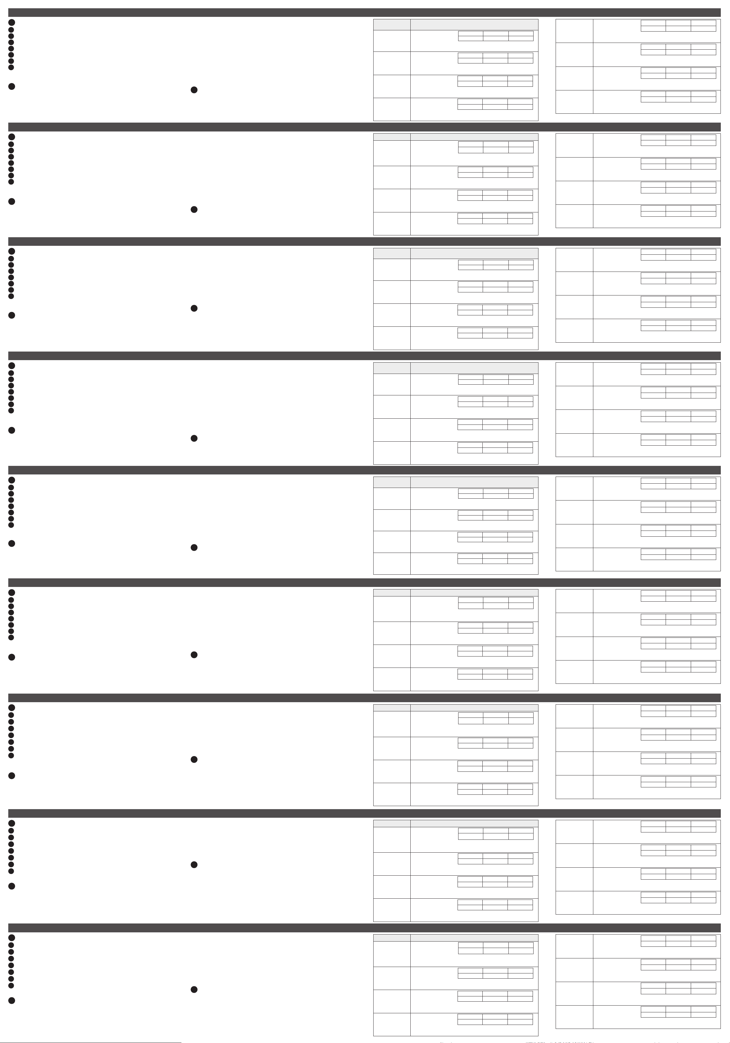
НастройкаусилениязвуканаAP902
Для настройки уровня усиления звука включите или выключите полюса
переключателей в соответствии со следующей таблицей:
Примечание:Полюса 1–3 используются для канала 2, а полюса 4–6 —
для канала 1.
Уровень
усиления Положениеотдельныхпереключателей
-6 дБ
ВЫКЛ v v v
ВКЛ
Полюс для канала 2: 1 2 3
Полюс для канала 1: 4 5 6
0 дБ
ВЫКЛ v v
ВКЛ v
Полюс для канала 2: 1 2 3
Полюс для канала 1: 4 5 6
+6 дБ
ВЫКЛ v v
ВКЛ v
Полюс для канала 2: 1 2 3
Полюс для канала 1: 4 5 6
+12 дБ
ВЫКЛ v
ВКЛ v v
Полюс для канала 2: 1 2 3
Полюс для канала 1: 4 5 6
+18 дБ
ВЫКЛ v v
ВКЛ v
Полюс для канала 2: 1 2 3
Полюс для канала 1: 4 5 6
+24 дБ
ВЫКЛ v
ВКЛ v v
Полюс для канала 2: 1 2 3
Полюс для канала 1: 4 5 6
+30 дБ
ВЫКЛ v
ВКЛ v v
Полюс для канала 2: 1 2 3
Полюс для канала 1: 4 5 6
+36 дБ
ВЫКЛ
ВКЛ v v v
Полюс для канала 2: 1 2 3
Полюс для канала 1: 4 5 6
2-канальная плата AP901 интерфейса Dante (для серии AP) / 2-канальная плата AP902 микрофонного/линейного предусилителя (для серии AP) www.aten.com
A
Panoramica dell'Hardware
1Porta link Dante
2viti
3ingresso linea per canale 2
4ingresso microfono per canale 2
5interruttore controllo gain
6ingresso linea per canale 1
7ingresso microfono per canale 1
Nota: Per prevenire danni al dispositivo, non inserire un segnale con livello di
linea nel canale di ingresso del microfono.
B
Inserire / Rimuovere la scheda di espansione
Nota: Ricordarsi di spegnere l'amplificatore AP206/AP212 e scollegare l'unità
dall'alimentazione prima di installare o rimuovere la scheda di espansione.
Per installare la scheda di espansione nell'amplificatore AP206/AP212:
1. Rimuovere la piastra dell'alloggio di espansione sul lato posteriore
dell'amplificatore AP206/AP212.
2. Inserire la scheda di espansione nell'alloggio di espansione dell'amplificatore.
Nota: Spingere un po' per inserire bene la scheda di espansione nel suo
alloggio.
3. Spingere con forza la testa di ciascuna vite finché non è ben inserita, poi
stringere le viti ruotandole in senso orario.
Per rimuovere la scheda di espansione:
Nota: Per sicurezza, spegnere l'amplificatore AP206/AP212 e aspettare 50
secondi prima di rimuovere la scheda di espansione.
1. Allentare ciascuna scheda un po' alla volta.
2. Tenere ferme le due viti e poi estrarre delicatamente la scheda di espansione.
3. Usare la piastra dell'alloggio di espansione per coprire l'alloggio vuoto, e
fissarla con le due viti.
C
Configurazione gain audio sull'AP902
Per regolare il livello di gain dell'audio, accendere o spegnere i poli come
indicato nella seguente tabella:
Nota: I poli dall'1 al 3 sono per il canale 2, i poli dal 4 al 6 sono per il canale 1.
Livello di gain Posizione degli interruttori individuali
-6 dB
OFF v v v
ON
Polo per il canale 2: 1 2 3
Polo per il canale 1: 4 5 6
0 dB
OFF v v
ON v
Polo per il canale 2: 1 2 3
Polo per il canale 1: 4 5 6
+6 dB
OFF v v
ON v
Polo per il canale 2: 1 2 3
Polo per il canale 1: 4 5 6
+12 dB
OFF v
ON v v
Polo per il canale 2: 1 2 3
Polo per il canale 1: 4 5 6
+18 dB
OFF v v
ON v
Polo per il canale 2: 1 2 3
Polo per il canale 1: 4 5 6
+24 dB
OFF v
ON v v
Polo per il canale 2: 1 2 3
Polo per il canale 1: 4 5 6
+30 dB
OFF v
ON v v
Polo per il canale 2: 1 2 3
Polo per il canale 1: 4 5 6
+36 dB
OFF
ON v v v
Polo per il canale 2: 1 2 3
Polo per il canale 1: 4 5 6
Scheda di espansione Dante AP901 2-CH per serie AP / Scheda di espansione preamp AP902 2-CH Mic/Line per serie AP www.aten.com
A
Vista general del hardware
1Puerto de conexión Dante
2tornillos
3entrada de línea para canal 2
4entrada de micrófono para canal 2
5interruptor de control de ganancia
6entrada de línea para canal 1
7entrada de micrófono para canal 1
Nota: Para evitar daños en el dispositivo, no alimente una señal de nivel de
línea a un canal de entrada de micrófono.
B
Instalación / Desinstalación de la tarjeta de expansión
Nota: Asegúrese de apagar el amplificador de potencia AP206/AP212 y
desconectar la unidad de la fuente de alimentación antes de instalar o retirar la
tarjeta de expansión.
Para instalar la tarjeta de expansión en el amplificador de potencia AP206/AP212:
1. Quite la placa de ranura de expansión de la parte trasera del amplificador de
potencia AP206/AP212.
2. Inserte la tarjeta de expansión en la ranura de expansión del amplificador.
Nota: Empuje un poco para que la tarjeta de expansión encaje
completamente en la ranura.
3. Aplique fuerza a cada cabezal de tornillo hasta que esté en su lugar y luego
apriete el tornillo girándolo en el sentido de las agujas del reloj.
Para quitar la tarjeta de expansión:
Nota: Por seguridad, apague el amplificador de potencia AP206/AP212 y luego
espere 50 segundos antes de quitar la tarjeta de expansión.
1. Afloje alternativamente cada tornillo.
2. Sujete los dos tornillos y luego extraiga con cuidado la tarjeta de expansión.
3. Utilice la placa de la ranura de expansión para cubrir la ranura vacía y fíjela
con los 2 tornillos.
C
Configuración de la ganancia de audio en AP902
Para ajustar el nivel de ganancia de audio, encienda o apague los polos como
muestra la siguiente tabla:
Nota: El polo 1 al polo 3 son para el canal 2 mientras que el polo 4 al polo 6
son para el canal 1.
Nivel de
ganancia Posición de interruptores individuales
-6dB
APAGADO v v v
ENCENDIDO
Polo para el canal 2: 1 2 3
Polo para el canal 1: 4 5 6
0dB
APAGADO v v
ENCENDIDO v
Polo para el canal 2: 1 2 3
Polo para el canal 1: 4 5 6
+6dB
APAGADO v v
ENCENDIDO v
Polo para el canal 2: 1 2 3
Polo para el canal 1: 4 5 6
+12dB
APAGADO v
ENCENDIDO v v
Polo para el canal 2: 1 2 3
Polo para el canal 1: 4 5 6
+18dB
APAGADO v v
ENCENDIDO v
Polo para el canal 2: 1 2 3
Polo para el canal 1: 4 5 6
+24dB
APAGADO v
ENCENDIDO v v
Polo para el canal 2: 1 2 3
Polo para el canal 1: 4 5 6
+30dB
APAGADO v
ENCENDIDO v v
Polo para el canal 2: 1 2 3
Polo para el canal 1: 4 5 6
+36dB
APAGADO
ENCENDIDO v v v
Polo para el canal 2: 1 2 3
Polo para el canal 1: 4 5 6
Tarjeta de expansión Dante AP901 de 2 canales para la serie AP / Tarjeta de expansión de preamplificador de línea/micrófono AP902 de 2 canales para la serie AP www.aten.com
A
Hardware Übersicht
1Dante Link Port
2Schrauben
3Line-Eingang für Kanal 2
4Mikrofoneingang für Kanal 2
5Schalter für Verstärkungsregelung
6Line-Eingang für Kanal 1
7Mikrofoneingang für Kanal 1
Hinweis: Führen Sie dem Kanal des Mikrofoneingangs kein Line-Pegelsignal
zu, um Schäden am Gerät zu vermeiden.
B
Die Erweiterungskarte installieren / entfernen
Hinweis: Stellen Sie sicher, dass Sie die AP206/AP212 Endstufe ausschalten und
das Gerät von der Stromversorgung trennen, bevor Sie die Erweiterungskarte
installieren oder entfernen.
Installation der Erweiterungskarte in die AP206/AP212 Endstufe:
1. Entfernen Sie die Platte des Erweiterungssteckplatzes an der Rückseite der
AP206/AP212 Endstufe.
2. Setzen Sie die Erweiterungskarte in den Erweiterungssteckplatz des
Verstärkers ein.
Hinweis: Drücken Sie ein wenig, um sicherzustellen, dass die
Erweiterungskarte fest in den Steckplatz einrastet.
3. Üben Sie Druck auf jeden Schraubenkopf aus, bis er fest sitzt. Ziehen Sie die
Schraube anschließend durch Drehen im Uhrzeigersinn fest.
Entfernen der Erweiterungskarte:
Hinweis: Schalten Sie die AP206/AP212 Endstufe aus Sicherheitsgründen aus und
warten Sie anschließend 50 Sekunden, bevor Sie die Erweiterungskarte entfernen.
1. Lösen Sie abwechselnd jede Schraube.
2. Halten Sie die beiden Schrauben fest und ziehen Sie die Erweiterungskarte
anschließend vorsichtig heraus.
3. Verwenden Sie die Platte des Erweiterungssteckplatzes, um den leeren
Steckplatz abzudecken, und befestigen Sie sie mit den 2 Schrauben.
C
Audioverstärkung auf dem AP902 konfigurieren
Schalten Sie den/die Pol(e) zum Einstellen des Pegels der Audioverstärkung wie
in der folgenden Tabelle dargestellt ein oder aus:
Hinweis: Die Pole 1 bis 3 sind für Kanal 2, die Pole 4 bis 6 sind für Kanal 1.
Verstärkungsstufe
Position individueller Schalter
-6dB
AUS v v v
EIN
Pol für Kanal 2: 1 2 3
Pol für Kanal 1: 4 5 6
0dB
AUS v v
EIN v
Pol für Kanal 2: 1 2 3
Pol für Kanal 1: 4 5 6
+6dB
AUS v v
EIN v
Pol für Kanal 2: 1 2 3
Pol für Kanal 1: 4 5 6
+12dB
AUS v
EIN v v
Pol für Kanal 2: 1 2 3
Pol für Kanal 1: 4 5 6
+18dB
AUS v v
EIN v
Pol für Kanal 2: 1 2 3
Pol für Kanal 1: 4 5 6
+24dB
AUS v
EIN v v
Pol für Kanal 2: 1 2 3
Pol für Kanal 1: 4 5 6
+30dB
AUS v
EIN v v
Pol für Kanal 2: 1 2 3
Pol für Kanal 1: 4 5 6
+36dB
AUS
EIN v v v
Pol für Kanal 2: 1 2 3
Pol für Kanal 1: 4 5 6
AP901 2-CH Dante Erweiterungskarte für AP Serie / AP902 2-CH Mic/Line Vorverstärker Erweiterungskarte für AP Serie www.aten.com
A
Survol du matériel
1Port de liaison Dante
2vis
3entrée ligne pour le canal 2
4entrée micro pour le canal 2
5commutateur de contrôle de gain
6entrée ligne pour le canal 1
7entrée micro pour le canal 1
Remarque : Pour éviter d'endommager l'appareil, n'envoyez pas de signal de
niveau ligne au canal d'entrée micro.
B
Installer / retirer la carte d'extension
Remarque : Veillez à éteindre l'amplificateur de puissance AP206/AP212 et à
le débrancher de la source d'alimentation avant d'installer ou de retirer la carte
d'extension.
Pour installer la carte d'extension dans l'amplificateur de puissance AP206/AP212 :
1. Retirez la plaque de la fente d'extension située à l'arrière de l'amplificateur
de puissance AP206/AP212.
2. Insérez la carte d'extension dans la fente d'extension de l'amplificateur.
Remarque : Poussez légèrement pour que la carte d'extension s'insère
complètement dans la fente.
3. Appuyez sur chaque tête de vis pour lui faire prendre sa place, puis serrez la
vis en la tournant dans le sens des aiguilles d'une montre.
Pour retirer la carte d'extension :
Remarque : Pour des raisons de sécurité, éteignez l'amplificateur de puissance
AP206/AP212 et attendez 50 secondes avant de retirer la carte d'extension.
1. Desserrez alternativement chaque vis.
2. Maintenez les deux vis et retirez la carte d'extension avec soin.
3. Utilisez la plaque de la fente d'extension pour couvrir la fente vide et fixez-la
à l'aide des 2 vis.
C
Configurer le gain audio sur l'AP902
Pour régler le niveau de gain audio, activer ou désactiver le(s) pôle(s) comme
indiqué sur le tableau suivant :
Remarque : Les pôles 1 à 3 sont destinés au canal 2 tandis que les pôles 4 à 6
sont destinés au canal 1.
Niveau de gain Position des commutateurs individuels
-6 dB
ARRET v v v
MARCHE
Pôle pour le canal 2 : 1 2 3
Pôle pour le canal 1 : 4 5 6
0 dB
ARRET v v
MARCHE v
Pôle pour le canal 2 : 1 2 3
Pôle pour le canal 1 : 4 5 6
+6 dB
ARRET v v
MARCHE v
Pôle pour le canal 2 : 1 2 3
Pôle pour le canal 1 : 4 5 6
+12 dB
ARRET v
MARCHE v v
Pôle pour le canal 2 : 1 2 3
Pôle pour le canal 1 : 4 5 6
+18 dB
ARRET v v
MARCHE v
Pôle pour le canal 2 : 1 2 3
Pôle pour le canal 1 : 4 5 6
+24 dB
ARRET v
MARCHE v v
Pôle pour le canal 2 : 1 2 3
Pôle pour le canal 1 : 4 5 6
+30 dB
ARRET v
MARCHE v v
Pôle pour le canal 2 : 1 2 3
Pôle pour le canal 1 : 4 5 6
+36 dB
ARRET
MARCHE v v v
Pôle pour le canal 2 : 1 2 3
Pôle pour le canal 1 : 4 5 6
AP901 Carte d'extension Dante 2 canaux pour la série AP / AP902 Carte d'extension préampli Micro/Ligne 2 canaux pour la série AP www.aten.com
A
Hardware Overview
1Dante link port
2screws
3line input for channel 2
4mic input for channel 2
5gain control switch
6line input for channel 1
7mic input for channel 1
Note: To prevent device damage, do not feed a line level signal to mic input
channel.
B
Installing / Removing the Expansion Card
Note: Make sure that you turn off the AP206/AP212 power amplifier and
disconnect the unit from the power source before installing or removing the
expansion card.
To install the expansion card into the AP206/AP212 power amplifier:
1. Remove the expansion slot plate on the rear side of the AP206/AP212
power amplifier.
2. Insert the expansion card into the amplifier’s expansion slot.
Note: Give a little push to get the expansion card fully seated in the slot.
3. Apply force to each screw head till it is in place, and then tighten the screw
by turning it clockwise.
To remove the expansion card:
Note: For safety purpose, please power off the AP206/AP212 power amplifier
and then wait for 50 seconds before removing the expansion card.
1. Alternately loosen each screw.
2. Hold the two screws and then gently pull out the expansion card.
3. Use the expansion slot plate to cover the blank slot, and secure it with the 2
screws.
C
Configuring Audio Gain on AP902
To adjust the audio gain level, switch on or off the pole(s) as the following table
shows:
Note: Pole 1 to pole 3 are for channel 2 while pole 4 to pole 6 are for channel 1.
Gain Level Position of Individual Switches
-6dB
OFF v v v
ON
Pole for Channel 2: 1 2 3
Pole for Channel 1: 4 5 6
0dB
OFF v v
ON v
Pole for Channel 2: 1 2 3
Pole for Channel 1: 4 5 6
+6dB
OFF v v
ON v
Pole for Channel 2: 1 2 3
Pole for Channel 1: 4 5 6
+12dB
OFF v
ON v v
Pole for Channel 2: 1 2 3
Pole for Channel 1: 4 5 6
+18dB
OFF v v
ON v
Pole for Channel 2: 1 2 3
Pole for Channel 1: 4 5 6
+24dB
OFF v
ON v v
Pole for Channel 2: 1 2 3
Pole for Channel 1: 4 5 6
+30dB
OFF v
ON v v
Pole for Channel 2: 1 2 3
Pole for Channel 1: 4 5 6
+36dB
OFF
ON v v v
Pole for Channel 2: 1 2 3
Pole for Channel 1: 4 5 6
BInstalling / Removing the Expansion Card
© Copyright 2023 ATEN®International Co. Ltd.
ATEN and the ATEN logo are registered trademarks of ATEN International Co., Ltd.
All rights reserved. All other trademarks are the property of their respective owners.
Released: 09/2023
AP901
2-CH Dante Expansion Card for AP Series
AP902
2-CH Mic/Line Preamp Expansion Card for
AP Series
Quick Start Guide
AP901 2-CH Dante Expansion Card for AP Series / AP902 2-CH Mic/Line Preamp Expansion Card for AP Series www.aten.com
AHardware Overview
AP901 Package Contents
1 AP901 2-CH Dante Expansion Card for
AP Series
1 user instructions
AP902 Package Contents
1 AP902 2-CH Mic/Line Preamp
Expansion Card for AP Series
2 5-pin Euroblock connectors with strain
relief (3.5mm)
1 user instructions
Support and Documentation Notice
All information, documentation, firmware,
software utilities, and specifications contained
in this package are subject to change without
prior notification by the manufacturer.
To reduce the environmental impact of our
products, ATEN documentation and software
can be found online at
http://www.aten.com/download/
Technical Support
www.aten.com/support
Scan for more information
Product Page Product Page
User Manual
1
2
2
4 53 76
AP901
AP902
AP212
AP902
AP901 AP902