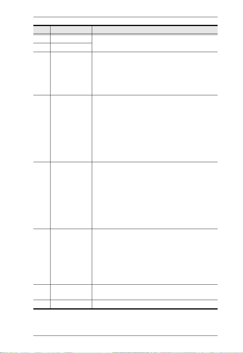
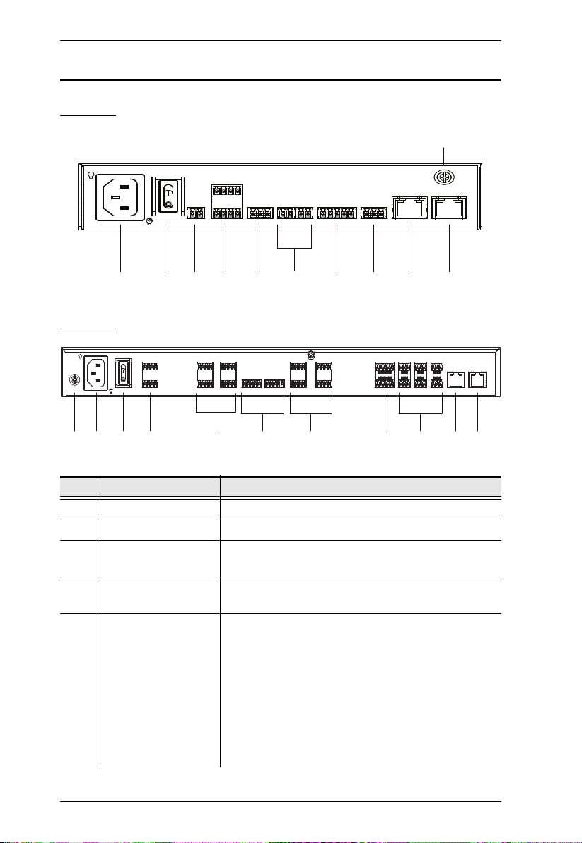
ATEN VK1200 User manual

ATEN Control System
User Manual
www.aten.com
Setup Guide
ATEN VanCryst™
VK1200 / VK2200
Control Box Gen.2

VK1200 / VK2200 Setup Guide
ii
Compliance Statements
FEDERAL COMMUNICATIONS COMMISSION INTERFERENCE
STATEMENT
This equipment has been tested and found to comply with the limits for a Class
A digital device, pursuant to Part 15 of the FCC Rules. These limits are
designed to provide reasonable protection against harmful interference when
the equipment is operated in a commercial environment. This equipment
generates, uses, and can radiate radio frequency energy and, if not installed and
used in accordance with the instruction manual, may cause harmful
interference to radio communications. Operation of this equipment in a
residential area is likely to cause harmful interference in which case the user
will be required to correct the interference at his own expense.
The device complies with Part 15 of the FCC Rules. Operation is subject to the
following two conditions: (1) this device may not cause harmful interference,
and (2) this device must accept any interference received, including
interference that may cause undesired operation.
FCC Caution
Any changes or modifications not expressly approved by the party responsible
for compliance could void the user's authority to operate this equipment.
Warning
Operation of this equipment in a residential environment could cause radio
interference.
Achtung
Der Gebrauch dieses Geräts in Wohnumgebung kann Funkstörungen
verursachen.
KCC Statement:
Industry Canada Statement
This Class A digital apparatus complies with Canadian ICES-003.

VK1200 / VK2200 Setup Guide
iii
RoHS
This product is RoHS compliant.
Contents
1. Introduction
Overview . . . . . . . . . . . . . . . . . . . . . . . . . . . . . . . . . . . . . . . . . . . . . . . . . . . 1
Package Contents . . . . . . . . . . . . . . . . . . . . . . . . . . . . . . . . . . . . . . . . .1
Before You Start . . . . . . . . . . . . . . . . . . . . . . . . . . . . . . . . . . . . . . . . . . 2
Front Panel . . . . . . . . . . . . . . . . . . . . . . . . . . . . . . . . . . . . . . . . . . . . . . . . . 3
Rear Panel . . . . . . . . . . . . . . . . . . . . . . . . . . . . . . . . . . . . . . . . . . . . . . . . . 5
Overall Installation Procedure. . . . . . . . . . . . . . . . . . . . . . . . . . . . . . . . . . . 7
2. Getting Started
Placement . . . . . . . . . . . . . . . . . . . . . . . . . . . . . . . . . . . . . . . . . . . . . . . . . . 8
Rack Mount . . . . . . . . . . . . . . . . . . . . . . . . . . . . . . . . . . . . . . . . . . . . . .8
Desktop . . . . . . . . . . . . . . . . . . . . . . . . . . . . . . . . . . . . . . . . . . . . . . . . 11
Powering the VK1200 / VK2200 . . . . . . . . . . . . . . . . . . . . . . . . . . . . . . . . 11
3. Initialization
ID, Network & License Configuration . . . . . . . . . . . . . . . . . . . . . . . . . . . . 12
Setting Controller ID . . . . . . . . . . . . . . . . . . . . . . . . . . . . . . . . . . . . . . 12
Determining the IP Address . . . . . . . . . . . . . . . . . . . . . . . . . . . . . . . . 12
Changing Network Settings. . . . . . . . . . . . . . . . . . . . . . . . . . . . . . . . . 12
Firmware . . . . . . . . . . . . . . . . . . . . . . . . . . . . . . . . . . . . . . . . . . . . . . . 13
Licenses . . . . . . . . . . . . . . . . . . . . . . . . . . . . . . . . . . . . . . . . . . . . . . . 14
4. Wiring
Wiring and Connecting to Devices . . . . . . . . . . . . . . . . . . . . . . . . . . . . . . 16
12 V DC Power Output . . . . . . . . . . . . . . . . . . . . . . . . . . . . . . . . . . . . 16
Relay . . . . . . . . . . . . . . . . . . . . . . . . . . . . . . . . . . . . . . . . . . . . . . . . . . 18
Digital I/O. . . . . . . . . . . . . . . . . . . . . . . . . . . . . . . . . . . . . . . . . . . . . . . 20
Bidirectional Serial. . . . . . . . . . . . . . . . . . . . . . . . . . . . . . . . . . . . . . . .23
RS-232 (3-Pin). . . . . . . . . . . . . . . . . . . . . . . . . . . . . . . . . . . . . . . .23
RS-232/422/485 (5-Pin). . . . . . . . . . . . . . . . . . . . . . . . . . . . . . . . . 24
Unidirectional IR / Serial . . . . . . . . . . . . . . . . . . . . . . . . . . . . . . . . . . . 24
IR Connection . . . . . . . . . . . . . . . . . . . . . . . . . . . . . . . . . . . . . . . . 25
Serial Connection . . . . . . . . . . . . . . . . . . . . . . . . . . . . . . . . . . . . .25
Control LAN. . . . . . . . . . . . . . . . . . . . . . . . . . . . . . . . . . . . . . . . . . . . . 26
5. ATEN Configurator
ATEN Configurator — VK6000 . . . . . . . . . . . . . . . . . . . . . . . . . . . . . . . . . 27

VK1200 / VK2200 Setup Guide
1
Overview
The VK1200 / VK2200 Control Box is an Ethernet-based controller device that
connects and integrates a spate of devices to provide single-access
configuration and convenient remote control for a room setting, such as
boardrooms and lecture halls.
It offers multiple bidirectional serial ports, relays, IR/serial ports, digital I/O,
and 12 V DC power output ports, as well as a dedicated control LAN port,
separate from the corporate LAN, for IP device management within a secure
subnetwork. In addition, it also supports a range of ATEN Expansion Boxes in
providing versatile scalability.
Once successfully connected, users will be able to configure all in-room
devices using the ATEN Configurator software — VK6000, and allow remote
control using ATEN Touch Panel, ATEN Keypads, and Android / iOS /
Windows mobile devices via the ATEN Control System app.
For a centralized management, the VK1200 / VK2200 can be connected to
ATEN Unizon, a global AV management platform software, allowing users to
control and monitor multiple ATEN Ethernet-based solutions across different
locations, including but not limited to ATEN Control Boxes, at the same time.
Package Contents
Make sure the following are present and in working condition:
1 VK1200 / VK2200 Control Box Gen. 2
1 power cord
1 foot pad set (4 pcs)
1 rack mount kit (VK2200 only)
1 user instructions
1 terminal block kit
Terminal Block VK1200 VK2200
2-Pin 7 20
3-Pin 2 6
5-Pin 1 4

Overview
2
Before You Start
The following is a checklist of the items to prepare / consider before you start:
Go through the numbers and types of ports available, and see if it satisfies
all of the devices you want to be controlled within your room setting.
Note: For more control port interfaces, up to 8 ATEN Expansion boxes per
expander model can be connected to the VK1200 / VK2200. See Compat-
ible Products on the product web page for details.
Consider the recommended maximum length of each interface cable, as
listed below, and choose an appropriate installation location for the
VK1200 / VK2200.
Note: The maximum allowed length of each interface cable may vary de-
pending on the cable quality.
Interface VK1200 VK2200
Bidirectional
RS232/422/485
Serial
3-Pin RS-232 1 6
5-Pin
RS-232/422/485 12
Unidirectional IR/Serial 2 8
Relay 4 8
Digital I/O 2 8
12 V DC Output 1 4
Ethernet 2 2
Interface Length (m)
RS-232 15
RS-422/485 350
Relay 30
I/O 30
IR 30

VK1200 / VK2200 Setup Guide
3
Prepare a PC with the following specifications, which may be used to set
the system settings of the VK1200 / VK2200 and run VK6000.
Windows 7 / 8 / 8.1 / 10
Installed with .Net Framework V4.5 or later
Take note of the network information and login credentials of each IP
device that will be connecting to and managed by the VK1200 / VK2200,
if any.
Front Panel
VK1200
VK2200
No. Component Description
1 relay LEDs
Lights green to indicate an active device connection or
signals being transmitted.
Blinks green once to indicate system startup, with the
buzzer beeping once
2I/O LEDs
3 IR / serial LEDs
4 serial LEDs
1
2
35
6
78
4
9121110
1
12
5
24
3689
710 11

Overview
4
5LAN LED Lights green to indicate successful connection to the
network.
6 Control LAN LED
7DC output
overload LED
Lights orange to indicate DC output exceeding the
maximum output threshold, with the buzzer beeping for 3
seconds.
Note: Please unplug any of the connected devices to keep
its total output under 12 V DC, 1 A / 2A for VK1200 /
VK2200 and restart the controller unit.
8 IR receiver / LED Passes the functions of a remote control to the VK1200 /
VK2200 in learning mode. The distance between the IR
remote and the receiver window should be kept under 10
cm with a direct line of sight.
The LED blinks green to indicate the unit is receiving
signals from an IR remote control
The LED lights green to indicate entering learning
mode, or IR learning success with the buzzer beeping
once.
9 USB port / LED Plugs in a USB device to upload Viewers (configured by
the VK6000) to the VK1200 / VK2200.
The LED blinks green to indicate that Viewers are being
uploaded, and lights green to indicate a successful
upload, with the buzzer beeping once upon USB plug-in
and once upon upload success.
The LED lights orange to indicate upload failure, with
the buzzer beeping 3 times for no available file found or
upload failure.
10 reset button
Clear all settings but network: Press and hold until
the front panel LEDs blink once, with the buzzer
beeping once (about 8 seconds). The LEDs and
buzzer will trigger once more when the reset is
complete.
Reset network settings: Short press once.
Note: For more reset functions, please refer to the user
manual.
11 LCD panel and
buttons
Use the Up, Down, and Enter buttons to display the unit’s
system information, and set its controller ID.
12 power LED Lights green when the unit is turned on.
No. Component Description

VK1200 / VK2200 Setup Guide
5
Rear Panel
VK1200
VK2200
No. Component Description
1 power socket Plugs in the power cord from an AC power source.
2 power switch Powers the unit on or off.
3 12 V DC output ports 1 / 4 DC output port(s) providing a total output of 12 V
DC, 1 / 2 A from the VK1200 / VK2200.
4 relay channels 4 / 8 channels; normally open, isolated relays with a
contact rating of 24 V DC, 2 A max.
5 I/O channels 2 / 8 channels that can be configured as digital inputs
or outputs, with the first pin being ground and the rest
being number pins.
Digital Input:
VDC Mode: 0 - 24 V DC; programmable range
of 1 - 24 V DC
Dry Contact Mode: Pull-up 2k Ω to +12 V DC
Digital Output: 300 mA sink from 24 V DC
1 2 3 4 5 106
11
78 9
11 1 2 3456 10
89
7

Overview
6
6 IR / serial ports 2 / 8 IR ports that can also be configured as RS-232
TX ports. pin 1: Signal / pin 2: Ground.
7 RS-232/422/485
serial ports
1 / 2 5-pin RS-232/422/485 serial ports by pin
assignment.
8 RS-232 serial ports 1 / 6 3-pin RS-232 serial ports with Tx, Rx and GND.
9 Control LAN Connects the unit to a
secure subnetwork,
separate from the corporate
LAN, for managing IP
devices and configuration
by the ATEN Configurator
VK6000, as well as for
remote control by ATEN
Keypads, Touch Panel or
the ATEN Control System
app on mobile devices.
Default network settings
when no dynamic IP
address is assigned, by
a DHCP server, after 30
seconds:
IP: 192.168.0.60 / mask:
255.255.255.0
10 LAN
Connects the unit to the
corporate LAN for remote
access and centralized
management by ATEN
Unizon.
Default network settings
when no dynamic IP
address is assigned, by
a DHCP server, after 30
seconds:
IP: 192.168.1.60 / mask:
255.255.255.0
11 grounding terminal Connects to the grounding wire.
No. Component Description

VK1200 / VK2200 Setup Guide
7
Overall Installation Procedure
The installation of the VK1200 / VK2200 shall be done in the following order:
Step 1 — Mounting the VK1200 / VK2200
see Placement, page 8.
Step 2 — Powering the VK1200 / VK2200
see Powering the VK1200 / VK2200, page 11.
Step 3 — Controller ID Setting and Initilization
see ID, Network & License Configuration, page 12.
Step 4 — Wiring and Connecting Devices
see Wiring and Connecting to Devices, page 16.
Step 5 — Adding the VK1200 / VK2200 on VK6000
see ATEN Configurator — VK6000, page 27.

VK1200 / VK2200 Setup Guide
8
Placement
Rack Mount
The VK1200 / VK2200 can be mounted onto a 19” (1U) system rack.
VK2200
1. Using the rack mount kit, attach the 2 mounting brackets onto the sides of
the unit with the 6 screws (M3x6) included.
2. Align the mounting brackets’ screw holes with that of the front of the rack,
and secure the unit onto the rack using 4 self-supplied screws.

Getting Started
9
VK1200
Note: For VK1200, the rack mount kit (2X-021G / 2X-049G) must be
purchased separately.
2X-049G (single rack mount)
1. Using the rack mount kit, attach the 2 mounting brackets onto the sides of
the unit with the 4 screws (M3x6) included.
2. Align the mounting brackets’ screw holes with that of the front of the rack,
and secure the unit onto the rack using 2 self-supplied screws.

VK1200 / VK2200 Setup Guide
10
2X-021G (dual rack mount)
1. Remove 2 screws at the bottom and 1 screw at the side from each of the
two VK1200 units, as shown below.
2. Use 4 of the screws from step 2 to secure the two VK1200 units together
with the link bracket. Then install the left and right mounting brackets
onto the sides of the units using 2 of the M3x5 and M3x6 screws included.
3. Align the mounting brackets’ screw holes with that of the front of the rack,
and secure the units onto the rack using 4 self-supplied screw.

Getting Started
11
Desktop
To place the VK1200 / VK2200 on a flat surface, such as a desk, simply attach
the foot pad set provided onto its 4 corners and place it on the surface.
Powering the VK1200 / VK2200
1. Use a grounding wire to ground the unit by connecting one end to the
grounding terminal (No. 1, Rear Panel, page 5) and the other end to a
suitable grounded object.
Note: Do not omit this step. Proper grounding helps prevent damage to the
unit from power surges and static electricity.
2. Plug the power cord into the unit’s power socket (No. 2, Rear Panel,
page 5), and connect it to an AC power source.
3. Using a self-supplied Cat 5e/6 cable, connect the unit to a secured
subnetwork via its Control LAN port (No. 9, Rear Panel, page 5).
4. (Optional) Using another Cat 5e/6 cable, connect the unit to the corporate
LAN, via its LAN port (No. 10, Rear Panel, page 5), for remote access
and/or centralized management by ATEN Unizon.
5. Start the unit by switching on its power switch (No. 3, Rear Panel,
page 5). Upon startup, all of VK1200 / VK2200’s interface LEDs will
blink once, with the buzzer beeping once.

12
ID, Network & License Configuration
Setting Controller ID
Use the LCD panel on the VK1200 / VK2200 to set its ID.
Note: Take note of the controller ID, which should be unique and unrepeated
if there are other controller devices within the same subnet.
Determining the IP Address
The network information of the VK1200 / VK2200 can be found on its LCD
panel, via Information, as illustrated below.
Changing Network Settings
There are two methods of changing the network settings of the VK1200 /
VK2200 — via IP Installer or web interface — on a PC within the same
subnet.
LAN Control LAN (CLAN)
DHCP When connected to a DHCP network, the VK1200 / VK2200 is
assigned with an IP address automatically upon startup.
Non-DHCP
When no dynamic IP address is assigned to it within 30 seconds after
startup, the VK1200 / VK2200’s default network settings are applied:
Default IP Address: 192.168.1.60
Subnet Mask: 255.255.255.0
Default IP Address: 192.168.0.60
Subnet Mask: 255.255.255.0

VK1200 / VK2200 Setup Guide
13
IP Installer
1. Using a Windows PC, download IP Installer zip file under Support and
Downloads from the VK1200 / VK2200’s product web page. Then extract
and execute IPInstaller.exe.
2. Select the VK1200 / VK2200 from the Device List, and select Use the
following IP address under IPv4 settings to change its IP address, subnet
mask, and default gateway.
Web Interface
1. Open a web browser, enter VK1200 / VK2200’s IP address, and log into
its web interface using the default access key — password. Upon login, the
user will be prompted and required to set a new password for the unit.
2. Click Settings
> Network, select Manually (DHCP off) from the Get
IP Address drop-down list, and change its network settings, namely IP
address, subnet mask, and default gateway.
Working as a DHCP Server
To set the VK1200 / VK2200 as a DHCP server for automatically
assigning dynamic IP addresses to the IP devices managed via its Control
LAN, do the following:
1. From the Get IP Address drop-down list, select Enable DHCP Server,
and optionally change the network settings of the VK1200 / VK2200,
namely IP address, subnet mask, and default gateway.
2. Next to IP Assigned Range, define the desired range of IP that can be
used for assigning IP addresses to the connecting IP devices.
3. Next to Lease Time, define the amount of time an assigned IP address
becomes available for use after the IP device it is previously assigned
to has been inactive for.

Initialization
14
Firmware
The current firmware version of the VK1200 / VK2200 is displayed on its web
interface main page, as shown below.
Upgrading Firmware
To upgrade the VK1200 / VK2200’s firmware, download the latest firmware
file from its product web page, and save it on the PC.
On the VK1200 / VK2200’s web interface main page, click Edit next to
General, and click Update under Firmware. Then browse for the downloaded
firmware file to upgrade.
Note: When Check FW Version is checked, the unit will compare its current
firmware version with that of the firmware file selected, and only allow
upgrading to a later version.

VK1200 / VK2200 Setup Guide
15
Licenses
A license is a software permit that the VK1200 / VK2200 grants to a mobile
device for remote control. The VK1200 / VK2200’s numbers of free and
maximum licenses are described below:
Adding Licenses
By default, the VK1200 / VK2200 is supplied with 2 free licenses for granting
remote control to 2 mobile devices.
To add additional licenses, click Edit next to Licenses on its web interface main
page, and click Add License. Then follow the on-screen instructions to export
a license file, apply for a license upgrade, and import the upgraded license file.
License VK1200 VK2200
Free Licenses 2
Max. Licenses 32

16
Wiring and Connecting to Devices
To connect the VK1200 / VK2200 to various devices, for integration and
control, refer to the corresponding interface for the wiring information of each.
12 V DC Power Outputs — see 12 V DC Power Output, page 16.
Relay — see Relay, page 18.
Digital I/O — see Digital I/O, page 20.
Bidirectional Serial — see Bidirectional Serial, page 23.
Unidirectional IR / Serial — see Unidirectional IR / Serial, page 24.
Control LAN — see Control LAN, page 26.
Note: All diagrams herein are exemplified using VK2200.
12 V DC Power Output
The VK1200 / VK2200 provides the following 12 V DC output(s):
It can power one or four independent hardware device(s), as illustrated below,
as well as relay or digital output devices.
Note: For powering relay or digital output devices connected, please refer to
Powered by 12 V DC Power Output, page 19, and Powered by 12 V DC
Power Output, page 21, respectively.
VK1200 VK2200
Number of Channels 14
Max. Power Supply DC 12 V, 1 A DC 12 V, 2 A

VK1200 / VK2200 Setup Guide
17
Independent Power Supply
When the total current exceeds the maximum threshold, the DC power
overload LED lights orange, and the alarm beeps for 3 seconds, while turning
the channel(s) off.
To correct power overload, turn off VK1200 / VK2200, disconnect all devices
connected to the 12 V DC outputs. Then turn the VK1200 / VK2200 back on
and reconnect the devices one at a time, to ensure the maximum current
threshold is not exceeded.
Power Supply: 12 V DC, 1 A /
2 A Max
Provides 12 V DC power to
independent hardware devices.
Connects to
12 V DC Output Ports
This manual suits for next models
1
Table of contents
Other ATEN Network Hardware manuals

ATEN
ATEN UC9020 StreamLIVE HD User manual

ATEN
ATEN VE44PB User manual

ATEN
ATEN Slideaway CL1008 User manual

ATEN
ATEN SN0108CO User manual

ATEN
ATEN CL1308 User manual

ATEN
ATEN UH-152 User manual

ATEN
ATEN Altusen SN0100 Series User manual

ATEN
ATEN VP2020 User manual

ATEN
ATEN PE7216 User manual

ATEN
ATEN CS231 User manual
Popular Network Hardware manuals by other brands

Alvarion
Alvarion BreezeACCESS VL System manual

Huawei
Huawei NE-HIC-2xSTM1/POS-SFP Specifications

Ubiquiti
Ubiquiti UniFi Cloud Key quick start guide

birddog
birddog NDI VideoWall user guide

Western Digital
Western Digital WDA4NC20000 - ShareSpace NAS 2TB HD 1TB x 2... Product specifications

ADC
ADC Migration Modules DSX-3 Quick reference guide