ATH-Heinl M72Z User manual

USER´S MANUAL
ATH M72Z

® Copyright by ATH-Heinl GmbH & Co. KG, 2019, All rights reserved / Misprint and technical changes reserved / Issue: 2019/02
- 2 -
INHALT
INTRODUCTION .............................................................................................................................- 4 -
General information’s ..................................................................................................................- 4 -
Description of tire changer...........................................................................................................- 5 -
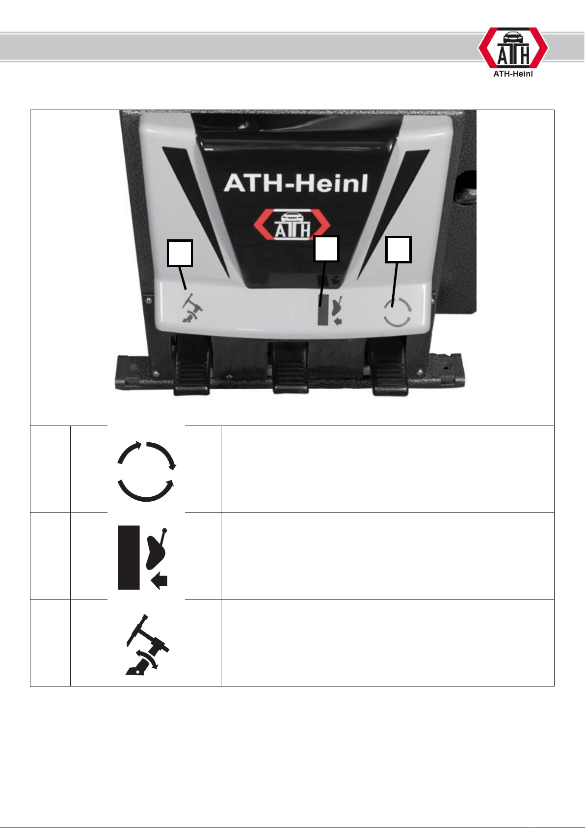
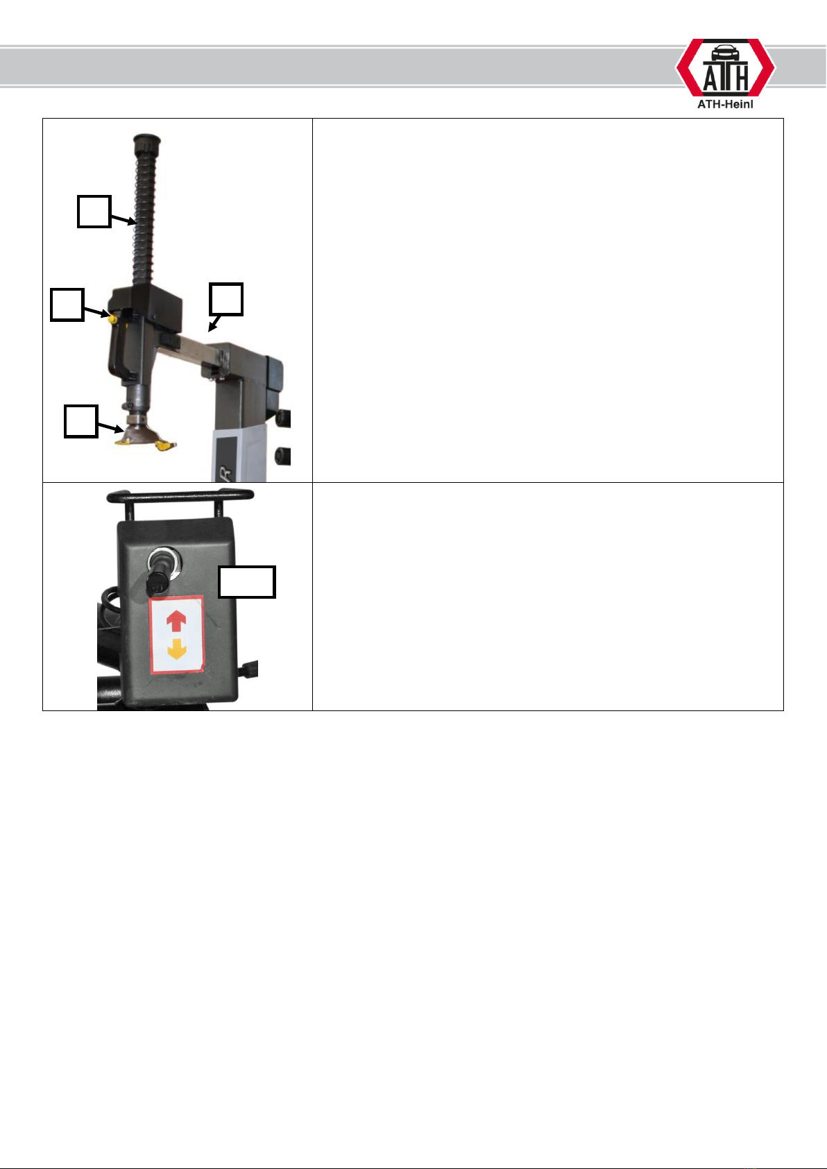
Operation of tire changer.............................................................................................................- 6 -
Technical data ............................................................................................................................- 8 -
Dimension drawing......................................................................................................................- 9 -
INSTALLATION.............................................................................................................................- 10 -
Transport and storage ...............................................................................................................- 10 -
Unpacking of machine ...............................................................................................................- 10 -
Scope of delivery.......................................................................................................................- 11 -
Place of installation ...................................................................................................................- 12 -
Fixing.......................................................................................................................................- 13 -
Electrical connection..................................................................................................................- 13 -
Pneumatic connection................................................................................................................- 14 -
Final works...............................................................................................................................- 14 -
OPERATION .................................................................................................................................- 15 -
Operation instructions ...............................................................................................................- 15 -
General instructions...................................................................................................................- 16 -
Bead breaking of a tire ..............................................................................................................- 18 -
Preparation for clamping of wheels.............................................................................................- 19 -
Clamping of the tires .................................................................................................................- 22 -
Adjustment of the mounting head ..............................................................................................- 23 -
Demounting of a tire .................................................................................................................- 24 -
Mounting of a tire .....................................................................................................................- 25 -
Filling of a tire...........................................................................................................................- 27 -
MAINTENANCE .............................................................................................................................- 29 -
Consumables for installation, maintenance and care.....................................................................- 29 -
Safety regulations for oil............................................................................................................- 30 -
Notice ......................................................................................................................................- 31 -
Maintenance plan or care plan....................................................................................................- 31 -
Troubleshooting........................................................................................................................- 32 -
Maintenance and service instructions ..........................................................................................- 33 -
Disposal ...................................................................................................................................- 36 -
KONFORMITÄTSERKLÄRUNG / DECLARATION OF CONFORMITY ......................................................- 37 -
APPENDIX....................................................................................................................................- 38 -
Pneumatic diagram ...................................................................................................................- 38 -
Electric diagram ........................................................................................................................- 39 -
WARRANTY NOTE.........................................................................................................................- 40 -
Product warranty ......................................................................................................................- 41 -
INSPECTION AND CERTIFICATION BOOK.......................................................................................- 42 -
Inspection ................................................................................................................................- 42 -
Scope of the inspection..............................................................................................................- 42 -
Technical data ..........................................................................................................................- 42 -
Name plate...............................................................................................................................- 42 -
Installation and handover certificate ...........................................................................................- 43 -
Inspection plan .........................................................................................................................- 44 -
Visual inspection (Authorized specialist) ......................................................................................- 45 -
ERSATZTEILBUCH / SPARE PART BOOK..........................................................................................- 49 -
Gehäuse / Machine body............................................................................................................- 50 -
Pedaleinheit / Pedal assembly ....................................................................................................- 52 -
Drehteller / Mainshaft................................................................................................................- 54 -

® Copyright by ATH-Heinl GmbH & Co. KG, 2019, All rights reserved / Misprint and technical changes reserved / Issue: 2019/02
- 3 -
Getriebe / Gear box...................................................................................................................- 56 -
Motor / Motor ...........................................................................................................................- 58 -
Montiersäule / Horizontal arm ....................................................................................................- 59 -
Montageturm Ausleger / Vertical arm..........................................................................................- 61 -
Schwenkzylinder / Buffer cylinder ...............................................................................................- 63 -
Druckdose vertikal / Hex shaft lock cylinder.................................................................................- 65 -
Druckdose horizontal / Square shaft lock cylinder ........................................................................- 66 -
Handgriff / Handle control valve .................................................................................................- 67 -
Abdrücker / Bead breaker ..........................................................................................................- 68 -
Zylinder für Abdrücker / Bead breaker cylinder ............................................................................- 69 -
Schnellentlüftung für Abdrücker (B) / Bead breaker cylinder quick valve assy (B)............................- 71 -
Schnellentlüftung für Abdrücker (E) / Bead breaker cylinder quick valve assy (E)............................- 72 -
Reifenfüller / Inflation gun .........................................................................................................- 73 -
Druckluftwartungseinheit / Air maintenance unit..........................................................................- 74 -
Hilfsarm / Assist arm .................................................................................................................- 75 -
NOTES.........................................................................................................................................- 78 -

® Copyright by ATH-Heinl GmbH & Co. KG, 2019, All rights reserved / Misprint and technical changes reserved / Issue: 2019/02
- 4 -
INTRODUCTION
General information’s
THIS MANUAL IS AN INHERENT PART OF THE MACHINE.
IT MUST BE READ AND UNDERSTOOD FROM THE OPERATOR.
THERE IS NO RESPONSIBILITY FOR DAMAGES, WHICH ARE RESULTING FROM
NON-OBSERVANCE OF THIS MANUAL OR THE GUILTY SAFETY REGULATIONS.
ATTENTION: Follow the instructions to avoid injuries or damages.
TIP: Gives further information’s to the functions and tips for using the machine efficiently.
Protective clothes must be worn for all works on the described machine.

® Copyright by ATH-Heinl GmbH & Co. KG, 2019, All rights reserved / Misprint and technical changes reserved / Issue: 2019/02
- 5 -
Description of tire changer
1
Handle with air valve
For locking / unlocking the horizontal and vertical movement of
the mounting head
2
Hexagon rod
For the vertical adjustment of the mounting head
3
Square rod
For the horizontal adjustment of the mounting head
4
Mounting head
For mounting / demounting of tires
5
Mounting tower
Swivelling backward
6
Turntable
For rotating the tire
7
Clamping rod
For clamping the rim
8
Grease holder
For storing the tire grease
9
Bead shovel
For breaking the bead off the rim
10
Housing
11
Foot pedal control
12
Inflator
For filling the tire
13
Air maintenance unit
A1
Bead roller
For losing the upper bead
A2
Bead roller
For losing the lower bead
A3
Second bead roller
For pressing the upper bead on a second position
A4
Bead pressing device
For pressing the upper bead on a third position
A5
Control of assist arm
For lifting and lowering of all assist arms
1
9
8
6
5
4
3
2
7
13
12
11
10
A1
A2
A3
A4
A5

® Copyright by ATH-Heinl GmbH & Co. KG, 2019, All rights reserved / Misprint and technical changes reserved / Issue: 2019/02
- 6 -
Operation of tire changer
1
Press the pedal downwards so that the turntable rotates clockwise.
Press the pedal upwards so that the turntable rotates counter
clockwise.
2
Press the pedal to work with the bead shovel. When you release it
the bead shovel goes back to the original position.
3
Press the pedal so that the mounting tower swivels backwards.
Press it again so that the mounting tower swivels forward again.
1
2
3

® Copyright by ATH-Heinl GmbH & Co. KG, 2019, All rights reserved / Misprint and technical changes reserved / Issue: 2019/02
- 7 -
By pressing the button (1) both the hexagon (2) and the square
(3) will be fixed in the adjusted position.
By pulling the button the fixing will be released and the mounting
head (4) can be adjusted.
Control of assist arm
A5.1 Control arm for the lifting and lowering of the bead rollers and
bead pressing arm.
3
2
1
4
A5.1

® Copyright by ATH-Heinl GmbH & Co. KG, 2019, All rights reserved / Misprint and technical changes reserved / Issue: 2019/02
- 8 -
Technical data
Centre hole diameter (z)
45 –130 mm
Rim diameter (B)
12 –27 Inch
Max. rim width (A)
Approx. 4 –13 Inch
[depending on offset (ET)]
Max. diameter (B + tire)
1050 mm
Max. bead breaker range
83 –350 mm
Max. bead breaker force
2500 kg
Rotatory force of turntable
1100 Nm
Revolutions of turntable
6 /12 rpm
Current supply
380 / 50 –16 V/Hz - A
(220 / 50 –16 V/Hz - A)
Power
0,75
Revolutions of motor
1400 / 2800 rpm
Working pressure
8 –10 Bar
(0,8 –1,0 Mpa)
Noise level
< 70 dB
Net weight
345 kg
Gross weight
390 kg
Definition of the rim
A = Width of rim (without “f”–rim edge)
B = Rim diameter (without “f”–rim edge)
f = Rim edge
h = Hump
t = Drop-centre
z = Centre ring
ET = Offset
1 = Rim centre
2 = Rim hub
1 inch = 2,54 cm

® Copyright by ATH-Heinl GmbH & Co. KG, 2019, All rights reserved / Misprint and technical changes reserved / Issue: 2019/02
- 9 -
Dimension drawing
1120-1740 mm
1770-2170 mm
1050-1550 mm

® Copyright by ATH-Heinl GmbH & Co. KG, 2019, All rights reserved / Misprint and technical changes reserved / Issue: 2019/02
- 10 -
INSTALLATION
The machine should be installed only by authorized personal according to the manual.
Transport and storage
Always use suitable means for transporting and positioning the
machine and keep attention to the gravity centre of the machine.
The machine should only be transported with the original packing.
Data:
Width
1150 mm
Length
1000 mm
Height
1850 mm
Storage temperature
-25 to +55 °C
Unpacking of machine
Remove the upper cover of the carton and make sure that there were no damages during
the transport.
Remove the safety bolts to get the machine from the pallet.
For taking the machine from the pallet use a suitable means (eventually with sling).
The packing material of the machine should be stored carefully.
Keep the packing material away from children as it could be dangerous for them.

® Copyright by ATH-Heinl GmbH & Co. KG, 2019, All rights reserved / Misprint and technical changes reserved / Issue: 2019/02
- 11 -
Scope of delivery
1
Cone #1
2
Cone #2
3
Cone #3
4
Cone #4
5
Plastic cover for Cone #3
6
Plastic cover for Cone #4
7
Distance-Adapter for Quick-nut
8
Quick-nut
9
Shaft
10
Rubber protection for turntable
11
Fitting ring for turntable
12
Bucket for tire lubricant (empty)
13
Brush for tire lubricant
14
Plastic sliders for mounting head
15
Roller for mounting head
16
Tire lever
17
Anchor bolts
18
Sealing kit and membrane for quick release valve
12
11
10
9
8
7
4
3
2
1
5
6
13
18
17
16
15
14

® Copyright by ATH-Heinl GmbH & Co. KG, 2019, All rights reserved / Misprint and technical changes reserved / Issue: 2019/02
- 12 -
Place of installation
The machine should be kept away from flammable and explosive materials as well as from solar radiation
and intensive light. The machine should also be installed in a well-ventilated place.
The tire changer must be placed on a concrete floor or similar solid flooring.
When selecting the place of installation, besides the soil condition also the guidelines and instructions of
the accident prevention regulations and workplace regulations must be observed.
When installing on an intermediate ceiling the capacity must be checked before. Generally, it is
recommended to ask a technical expert when installing on an intermediate ceiling.
It is not allowed to install the machine outside, but only inside, as the machine has no corresponding safety
provisions (IP-protection, zinc coated and so on)
Temperature
4-40 °C
Sea level
< 1000 m
Air humidity
50% at 40°C –90% at 20 °C

® Copyright by ATH-Heinl GmbH & Co. KG, 2019, All rights reserved / Misprint and technical changes reserved / Issue: 2019/02
- 13 -
Fixing
It is recommended to fix the machine on the intended points with anchor screws M16 or corresponding
anchors on the floor.
Bore holes, pay attention
in doing so to the
necessary boring depth
A and the boring
diameter of the anchor
manufacturer.
Clean the inner of the
holes
Put the anchor bolts into
the holes until you reach
the bottom of the hole.
Tighten the nut with the
necessary torque
specified by the
manufacturer. Clamping
thickness B depends on
flooring.
Electrical connection
Here, the general and local regulations must be observed. Therefore, this step must be
performed only by an expert.
Pay attention to the correct current supply. (see technical data).
The connection should be made with a 5-phase 16 A CEE plug (not in scope of delivery).
The machine must be grounded.
The voltage deviation should be max. 0,9 –1,1 times of the nominal voltage range and the frequency
deviation should be max. 0,99 –1,01 times of the frequency range.
To guarantee this, necessary safety measures must be made.
For finishing the works the rotating direction of the motor (at 400V) must be checked.
Press the pedal which is responsible for the rotating direction of the turntable downwards.
In doing so the turntable should rotate clockwise.
If the turntable rotates in the wrong direction, change two phases in the connecting plug.

® Copyright by ATH-Heinl GmbH & Co. KG, 2019, All rights reserved / Misprint and technical changes reserved / Issue: 2019/02
- 14 -
Pneumatic connection
The air pressure should correspond to the technical
data.
The maximum respectively minimum pressure
guarantees a correct function without possible
damages.
It is recommended to use a non-return valve (D) –it
is NOT in the scope of delivery.
Connect the compressed air supply to the
maintenance unit (4).
For a correct adjustment, all information’s in the
chapter “Maintenance and Service instructions”must
be observed now.
Final works
Retighten all fixing screws for the clamping jaws and the screws on the slide face of the
turntable approx. 20 days after the first operation.
D
4

® Copyright by ATH-Heinl GmbH & Co. KG, 2019, All rights reserved / Misprint and technical changes reserved / Issue: 2019/02
- 15 -
OPERATION
Operation instructions
TIRE CHANGER
RISKS FOR HUMAN AND ENVIRONMENT
•Bursting tires, balancing weights or rim parts which blow away can cause
serious injuries.
•By abrasion of brake linings harmful dust will be released.
PRECAUTIONS AND RULES OF CONDUCT
•Do only use impact screw drivers which are not blowing onto the rim.
•To avoid dust, only clean rims and tires wet; if possible use washer for tires.
•Remove dust on the brake drums with exhausting bell about a suitable industrial
vacuum cleaner. Use equipment of Category U for no asbestos dust and
equipment of Category K1 for asbestos-containing dust.
•Do only use faultless rims. By flat mould rims, which are stick together by spot
welding, the seam resistance must be checked.
•Faulty tires must be made unusable.
•While inflating the tire position a safety device for collecting parts which blow
away.
•Keep persons away from the danger zone.
•On tire changers with vertical positioned tires the working with heavy weight
tires (e.g. earth mover tire moulds) must be made by 2 persons.
•At tires with a diameter > 1,4 m or a weight > 200 kg safety device against
falling over must be used.
•The inflating of tires must be observed and the maximum mounting pressures
are not allowed to exceed.
BEHAVIOUR IN CASE OF ERROR
Detected errors must be reported to the responsible person.
FIRST AID
Emergency call:
•Keep in mind in case of an accident not only to save the injured person and to
render first aid but also to secure the scene of accident.
•Report every accident immediately to the responsible person.
•Place of first aid kit and first aid book: ___________________
•Record all information in the first aid book.
MAINTENANCE, DISPOSAL
Reparations are only allowed to be made by the after sales service of the
manufacturer.

® Copyright by ATH-Heinl GmbH & Co. KG, 2019, All rights reserved / Misprint and technical changes reserved / Issue: 2019/02
- 16 -
General instructions
THE TIRE CHANGER IS ONLY ALLOWED TO BE OPERATED BY SKILLED AND TRAINED TECHNICIANS OVER
18 YEARS.
THE MACHINE IS ONLY TO BE USED ACCORDING TO ITS INTENDED AND SPECIFIED USE.
FOR A CORRECT MOUNTING OF THE RIMS IT IS PROBABLY NECESSARY TO USE A CORRESPONDING
ACCESSORY (e.g. PLASTIC PROTECCTION FOR CLAMPING JAWS, MOUNTING HEAD AND MOUNTING
LEVER OR MOTORCYCLE ACCESSORY).
DO ALWAYS TAKE THE INTENDED MATERIAL, e.g. THE CORRECT TIRE DIMENSION, SUITABLE VALVES
OR THE CORRECT MOUNTING GREASE.
BEFORE MOUNTING OR DEMOUNTING CHECK ALL COMPONENTS. THOSE MUST NOT HAVE ANY
DAMAGES.
PAY ATTENTION TO POSSIBLE SPECIAL MOUNTING OR DEMOUNTING INSTRUCTIONS OF THE TIRE
MANUFACTURER.
DURING OPERATION PAY ATTENTION TO DANGEROUS SITUATIONS. IF THERE ARE ANY DANGERS
SWITCH OFF THE MACHINE IMMEDIATELY, DISCONNECT THE CURRENT SUPPLY AND THE AIR SUPPLY.
FOLLOWING CONTACT YOUR DISTRIBUTOR.
DURING MOUNTING OR DEMOUNTING OR INFLATING OF TIRES OBSERVE STRICTLY THE GUIDELINES
OF WDK (TRADE ASSOCIATION OF THE GERMAN RUBBER INDUSTRY).
MOUNTING OR DEMOUNTING OF TIRES WHICH ARE OLDER THAN 30 YEARS CAN CAUSE ACCIDENTS OR
DAMAGES.
Pay attention to possible shearing points on the tire changer.
Be careful while filling tires - damaged or dirty tires can cause serious injuries.
Moving parts of the machine can catch loose clothing, long hairs or jewellery.
-
- ALL WARNING SYMBOLS MUST BE ALWAYS READABLE; THEY MUST BE REPLACED IMMEDIATELY IN
CASE OF ANY DAMAGE ON IT.

® Copyright by ATH-Heinl GmbH & Co. KG, 2019, All rights reserved / Misprint and technical changes reserved / Issue: 2019/02
- 17 -
At some rims, the drop-centre in the middle of the rim is very flat.
Or there is no drop-centre.
In some countries, the sale of this type of rims is not allowed.
At some rims, the drop-centre in the middle of the rim is very deep
so that the tires must be pressed into very deep while mounting or
demounting. This increases the danger that the tire will be
damaged.
Some tires have a pressure control system. While mounting or
demounting a tire this system may not be damaged.

® Copyright by ATH-Heinl GmbH & Co. KG, 2019, All rights reserved / Misprint and technical changes reserved / Issue: 2019/02
- 18 -
Bead breaking of a tire
Preparation
Before operating the machine check the following points:
- Checking of oil level, water level and air pressure of the maintenance unit.
- Checking, if the machine is correctly connected to the power supply.
Screw out the inlet of the wheel valve and let the air completely
escape.
Turn respectively clamp the turntable in such a position so that no
components (cylinder, pneumatic screwing’s and so on) can be
touched by the tire.
Now turn the rim so that you can first break the bead of the outer side
of the rim.
Lay now the pressure less wheel lateral on the special rubber pad on
the machine housing.
With the lever, the bead shovel can be put on the outer side of the
tire. For a damage-free mounting the shovel must be positioned
approx. 1 cm away from the rim edge.
Press the pedal for the bead breaker until the tire is dismantled from
the rim, then IMMEDIATELY release the pedal.
Turn the wheel further and repeat the bead breaking process until the
tire is completely dismantled from the rim.
For making the following demounting of the tire easier respectively
gentler for the tire and rim it is recommendable to coat the nascent
tire and rim parts while plunging the bead shovel in sufficiently with a
marketable tire bead lubricant.
Do only use approved lubricants!
Make the same with the second wheel side.

® Copyright by ATH-Heinl GmbH & Co. KG, 2019, All rights reserved / Misprint and technical changes reserved / Issue: 2019/02
- 19 -
Preparation for clamping of wheels
Before clamping the wheels, check the following points:
- Removing dirt and old counter-weights of the wheel
- Check the total weight of the wheel
In the process of placing the tire on the turntable, the kind of lifting and handling the tire is
determined.
By a total weight under 25kg the lifting can be operate by one person.
By a total weight over 25kg the user has to operate by 2 persons or a wheel lifting device.
By a total weight over 50kg the user has to operate with a wheel lifting device.
-Choose the right Configuration
Adapter for standard rim
Adapter for rim with concave center hole

® Copyright by ATH-Heinl GmbH & Co. KG, 2019, All rights reserved / Misprint and technical changes reserved / Issue: 2019/02
- 20 -
Apaptor for reversed rims
Adaptor for light truck rims
Table of contents
Popular Industrial Equipment manuals by other brands

Midwest Specialties
Midwest Specialties FlexArm A-32 Installation & operation manual

Global Industrial
Global Industrial B237006 Assembly instructions

Dover
Dover DESTACO RFE Series Service manual

TruSteel
TruSteel AutoVap30 user manual

Chentronics
Chentronics SureSparc BD-5 Installation and operation manual

Siemens
Siemens Simotics operating instructions