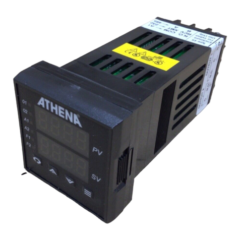
Athena 1ZC Series User manual

SERIES
1ZC
COMMUNICATING
SUB-PANEL
TEMPERATURE
CONTROLLER
Operating
Instructions

2
For Technical Assistance,
Call Toll Free 800.782.6776 (in the U.S.)
or 610.828.2490 (from anywhere in the world),
Platinel®is a registered trademark of Englehard Industries
Multi-Comm™is a trademark of Athena Controls, Inc.
©Copyright 2006, Athena Controls, Inc.

3
Table of Contents
Introduction, Precautions, Features, and Safety Warnings . . . . . . . . . . . . . . . . . . . . . . . . .4
Pre-Wire Setup . . . . . . . . . . . . . . . . . . . . . . . . . . . . . . . . . . . . . . . . . . . . . . . . . . . . . . . . . . .5
Input, Output, Communications, and Power Wiring . . . . . . . . . . . . . . . . . . . . . . . . . . . . . .6-8
Mounting and Repositioning . . . . . . . . . . . . . . . . . . . . . . . . . . . . . . . . . . . . . . . . . . . . . . . .8
Outputs . . . . . . . . . . . . . . . . . . . . . . . . . . . . . . . . . . . . . . . . . . . . . . . . . . . . . . . . . . . . . . . . .9
Operation . . . . . . . . . . . . . . . . . . . . . . . . . . . . . . . . . . . . . . . . . . . . . . . . . . . . . . . . . . . . . . .9
Parameters . . . . . . . . . . . . . . . . . . . . . . . . . . . . . . . . . . . . . . . . . . . . . . . . . . . . . . . . . .10-15
Communications Message Examples . . . . . . . . . . . . . . . . . . . . . . . . . . . . . . . . . . . . . .16-18
Troubleshooting . . . . . . . . . . . . . . . . . . . . . . . . . . . . . . . . . . . . . . . . . . . . . . . . . . . . . . . . .18
Communications Error Codes . . . . . . . . . . . . . . . . . . . . . . . . . . . . . . . . . . . . . . . . . . . . . .19
Specifications . . . . . . . . . . . . . . . . . . . . . . . . . . . . . . . . . . . . . . . . . . . . . . . . . . . . . . . . . . .20
Ordering Information . . . . . . . . . . . . . . . . . . . . . . . . . . . . . . . . . . . . . . . . . . . . . . . . . . . . .21
Warranty/Repairs . . . . . . . . . . . . . . . . . . . . . . . . . . . . . . . . . . . . . . . . . . . . . . . . . . . . . . . .23

Features
DIN Rail (NS-35/7.5) Mountable Enclosure
Stackable to Required Number of Zones
Each Zone Independently Powered
Pluggable Terminal Block for Easy Wiring
Optically Isolated Inputs and Outputs
Selectable Thermocouple, RTD, Current,
or Voltage Input
On/Off Through Full PID Operation
Autotuning - Heat or Cool
Adjustable On/Off Output Hysteresis
and Deadband
Dual Outputs, Each Configurable as
Reverse/Direct-Acting or Alarm
Alarm Inhibit Mode
Loop Break Alarm
Safety Warnings
In addition to presenting a potential fire
hazard, high voltage and high temperature
can damage equipment and cause severe
injury or death. When installing or using
this instrument, follow all instructions
carefully and use approved safety controls.
Electrical connections and wiring should
be performed only by suitably trained
personnel.
Do not locate this instrument where it is
subject to excessive shock, vibration, dirt,
moisture, oil, or other liquids. The safe
operating temperature range for this unit is
32°F to 140°F (0°C to 60°C).
4
Series 1ZC Communicating Sub-Panel Temperature Controller
Introduction
The Series 1ZC is a nonindicating control
module, designed to be mounted on a
standard DIN rail, that may be used to
control the temperature of a single control
zone via a remote personal computer,
PLC, or other serial communications
device. It features two independent outputs,
each configurable as either direct-acting,
reverse-acting, or alarm. Discrete LEDs
illuminate to provide an indication of
system status and output activity.
To configure the 1ZC, set up control
parameters, and communicate with the
controller via its standard RS-485 interface,
a communications program that incorpo-
rates the Athena+ Protocol data message
formats is required. Athena’s Multi-Comm™
software, which may be used to control up
to 254 Series 1ZC controllers remotely
from a PC*, may be used for this purpose.
Precautions
After unpacking, inspect the instrument
and shipping carton for any physical
damage that may have occurred in
shipping. Never attempt to install and
use a damaged unit. Save all packing
materials and report any damage to the
carrier immediately. Verify that the ordering
code on the instrument label matches what
was ordered before proceeding.
*PC requirements: 386SX or better, 1 Mb of free
hard disk space, MS-Windows 3.1 and MS-DOS
5.0 or later, and RS-485 interface (or RS-232
with RS-485 converter).
5
Pre-Wire Setup
Note:
Do not use a screwdriver or other
metal object to pry open the case. Only
slight hand pressure is required.
Note:
The 1ZC communicates
according to the RS-485 standard. This
allows for up to 32 devices to be on a
single twisted pair. Use of a signal
repeater will allow more devices to
be addressed.
Before wiring the 1ZC controller, the
network address of each unit must be set
using a binary DIP switch located on the
controller’s circuit board. DO NOT
ATTEMPT TO CONNECT POWER
WIRING BEFORE COMPLETING
THIS STEP.
Pull apart case sides to disengage locking
tabs while pulling out the black bezel.
Locate the 8-position DIP switch and
assign a unique network ID to each
controller by setting the DIP switch to
the appropriate binary number (Fig.1).
Valid network IDs are 1 to 254. (Zero
and 255 may not be used.)
Switch Number Hex Decimal
Address Descriptions 1 234 5 678
Equivalent Equivalent
Factory Use ONLY OFF OFF OFF OFF OFF OFF OFF OFF 00h 0
First usable address ON OFF OFF OFF OFF OFF OFF OFF 01h 1
Second usable address OFF ON OFF OFF OFF OFF OFF OFF 02h 2
Third usable address ON ON OFF OFF OFF OFF OFF OFF 03h 3
Fourth usable address OFF OFF ON OFF OFF OFF OFF OFF 04h 4
Last usable address OFF ON ON ON ON ON ON ON FEh 254
Default communications ON ON ON ON ON ON ON ON FFh 255
settings: 2400 Baud; 8, n, 1
1ZC DIP Switch Settings
Figure 1. Binary Code DIP Switch for
setting network IDs for each controller.
Series 1ZC Communicating Sub-Panel Temperature Controller
When reassigning a
network ID after Input/
Output/Power wiring is
attached, disconnect wiring
connector, then remove board as noted
earlier. NEVER ATTEMPT TO REMOVE
CIRCUIT BOARD WITH POWER WIRING
ATTACHED. HAZARDOUS VOLTAGE IS
PRESENT ON CIRCUIT BOARD.

Input Wiring
Note:
Thermocouple circuit resistance
should not exceed 100 ohms for
rated accuracy; errors will occur at
higher resistance values. If shielded
thermocouple wire is used, terminate
the shield only at controller end.
Figure 3. Thermocouple Input Wiring.
Make sure that you are using the
appropriate thermocouple and extension
wire. Connect the negative lead (generally
colored red in ISA-type thermocouples) to
contact #1; connect the positive lead to
contact #2. Extension wires must be the
same polarity as the thermocouple.
6
Series 1ZC Communicating Sub-Panel Temperature Controller
Input, Output,
Communications,
and Power Wiring
IMPORTANT: All electrical wiring
connections should be made only by
trained personnel, and in strict accordance
with the National Electrical Code and
local regulations.
The 1ZC controller has built-in circuitry to
reduce the effects of electrical noise (RFI)
from various sources. However, power and
signal wires should always be kept
separate. We recommend separating
connecting wires into three bundles:
power; signal; and output. These bundles
should then be routed through individual
conduits. Shielded sensor cables should
always be terminated to earth ground
at the controller end only.
If additional RFI attenuation is required,
install a noise suppression device such as
an R.C. snubber across the external noise
source. If you wish, you may order this
suppressor directly from Athena; specify
part number 235Z005U01.
Figure 2. 1ZC Contact Identification
Legend:
1 Sensor (-) – Thermocouple, RTD,
or Process
2 Sensor (+) – Thermocouple, RTD,
or Process
3 Sensor – Bias for RTD
4 Communications – RS-485 “A” I/O line,
bidirectional
5Communications – RS-485 “B” I/O line,
bidirectional
6Output 1, Relay – N.O., solid-state relay:
Load; Process: (+)
7Output 1, Relay – Common, solid-state
relay: Load; Process: (-)
8Output 2, Relay – N.O., solid-state relay:
Load; Process: (+)
9Output 2, Relay – Common, solid-state
relay: Load; Process: (-)
10 Power, Input – L2 (reference only, no
polarity required)
11 Power, Input – L1 (reference only, no
polarity required)

7
Series 1ZC Communicating Sub-Panel Temperature Controller
Figure 5. Process and Linear Input Wiring.
Voltage Inputs: Connect the positive volt-
age input to contact #2; the negative input
to contact #1. Current Inputs: Connect the
positive current input to contact #2; the
negative input to contact #1.
Legend:
Output 1
Contact #6: Relay-N.O. (Normally
Open contact)
Solid-state relay: Load
Process: (+)
Contact #7: Relay-Common
Solid-state relay: Load
Process: (-)
Output 2
Contact #8: Relay-N.O. (Normally
Open contact)
Solid-state relay: Load
Process: (+)
Contact #9: Relay-Common
Solid-state relay: Load
Process: (-)
Output Wiring
Figure 6. Output Wiring. The 1ZC has
two outputs. Each can be configured
with any one of four types of outputs:
mechanical relay, solid-state relay,
pulsed dc, and 4-20 mA.
Figure 4. 2- and 3-Wire RTD Input Wiring.
The 1ZC accepts input from 2- or 3-wire,
100 ohm platinum resistance temperature
detectors (RTDs). Connect 2-wire RTDs to
contacts #1 and #2, with a jumper across
contacts #2 and #3. Keep leads short and
use heavy gauge copper extension wire to
minimize lead resistance, which can result
in a reading error of 5°F per ohm. For long
runs, 3-wire RTDs should be used.
Communications Wiring
Figure 7. Communications Wiring.
The 1ZC conforms to the RS-485
communications standard. Connect
communications wiring to contacts #4
and #5 as indicated in the diagram below.
If the host computer does not have an
RS-485 communications board, then an
RS-232 to RS-485 converter will need to
be used. Note: Contact Athena for a rec-
ommended RS-485 converter. Connect
the converter to your host computer’s
serial communications port. Default
communications settings are: Baud rate =
2400 and Data format = 8-N-1.

8
Series 1ZC Communicating Sub-Panel Temperature Controller
Power Wiring
Figure 8. Connect power wiring to
contacts #10 and #11 as shown.
Mounting and
Repositioning
Follow the instructions for mounting and
repositioning the1ZC given in Figures
9-13 below.
Mounting the Controller
Figure 9. Orient the controller so that
the wiring label is visible after the unit
is attached to the DIN rail.
Figure 10. Place fixed catch onto DIN
rail, rotate unit downward. The 1ZC will
snap onto the rail.
Repositioning the Controller
Figure 11. To reposition the 1ZC, insert a
thin-shank straight blade screwdriver
into the slot on the underside of the unit.
Figure 12. Apply a squeezing motion
against the screwdriver and opposite
side of the case. This will disengage the
sliding catch.
Figure 13. While squeezing the
screwdriver and case, rotate the 1ZC
upward.This will release the unit from
the DIN rail.

9
Series 1ZC Communicating Sub-Panel Temperature Controller
Outputs
Note:
The Type “B” output is a mechani-
cal device and subject to wear. To
extend the life of the relay, set the Cycle
Time for the relay output to the longest
duration that still affords good control.
Type “B” relay outputs should not be
used in proportional applications to
switch load power directly.
When you ordered your 1ZC controller,
specific output types were specified, desig-
nated as “B”, “F”, “S”, or “T”. You also had
the option of configuring your controller
with either one or two output actions. The
numbers below are the suggested cycle
times for most typical applications.
For Control Output Type Select
Cycle Time
(in seconds)
B Electromechanical Relay >15
F 4 to 20 mA 0.2
S Pulsed 20 Vdc 0.2
T Solid-State Relay 15*
*“T” outputs directly driving non-inductive loads
(small heaters) can have cycle times as low as
0.2 seconds.
Operation
Figure 14. LED status indicators.
Label Location Function
(Above
Contact #)
SENSOR #2 Illuminates when
ERROR sensor is discon-
nected or out of
range (causes
Outputs 1 and 2
to be disabled).
RXD #4 Illuminates when
receiving data.
TXD #5 Illuminates when
transmitting data.
OUTPUT 1 Between Illuminates when
#6 and #7 energized.
OUTPUT 2 Between Illuminates when
#8 and #9 energized.
POWER/ Between Blinks when power
RUN #10 and #11 is applied and unit
is running.
The Series 1ZC controller is a nonindicating
instrument designed for use with an external
communications program. Athena offers
Multi-Comm™, a Windows-based graphical
user interface for setting and controlling up
to 254 1ZC controllers. For a demo copy of
this program, call 1-800-782-6776 or contact
an Athena Controls representative.
If you are writing your own software, be sure
that it complies with the Athena+ messaging
protocol and parameter identification codes
as described on the following pages.
Startup
When power is first applied, the LED
indicators will illuminate momentarily
while the instrument goes through a series
of diagnostic checks to verify proper
operation.
IMPORTANT: On initial startup, there is a
possibility that outputs may be activated.
The 1ZC has six status indicators
(Fig. 14), described in the table, right.
Table 1. LED indicators, location,
and function.

10
Series 1ZC Communicating Sub-Panel Temperature Controller
Parameters
On initialization, default parameter settings
relating to controller configuration and
communications were loaded into the
controller’s memory. To change these
parameters to suit your specific application
requirements, you must use the Athena+
protocol communications message syntax
described in the section titled
“Communications Message Examples.”
On the next page is a list of legal
parameters and the information required
within your program to configure them.
For examples of typical communications
messages, refer to pages 16-18.
We recommend setting parameters in the
following order:
1) Communications (Network ID set by
DIP switch)
Baud Rate
Data Format
Transmit Delay
2) Input Type
3) Input Low Scale and High Scale
(if linear input is specified)
4) Output Type (Two independent outputs
are available)
5) Output Modes
For PID Outputs:
Output Action
Cycle Time
Low and High Limits
For Outputs Configured as Alarms:
Output Alarm Action
Output Alarm Operation
Output Alarm Delay
Output Alarm Inhibit Time
For On/Off Outputs:
Output Action
6) Operating Mode (Normal, Autotune,
Manual, Standby)
7) Load default communication
parameters procedure:
Disconnect power
Set all DIP switches to ON position
Apply power
Disconnect power
Set ID 2 - 255
Default communication parameters
are 2400 Baud, 8-N-1

11
Series 1ZC Communicating Sub-Panel Temperature Controller
1ZC Parameter Codes
“X”s mark parameters that are supported by
the 1ZC and “O”s that are not supported.
Number Name Read Write Data Field Value
1 Controller Type X 0 4
2 Software Version X 0
3 Communications Version X 0
4 Status Byte X 0 This field contains the ASCII
representation of an 8-bit value
in which the bit assignments are as
follows:
X Process Input Error
0 Always Zero
0 Always Zero
X Loop Break
0 Always Zero
0 Always Zero
X 01 (Alarm) Active
X 02 (Alarm) Active
If a bit at a location marked as “X”
is set, then the condition is TRUE.
For example, a “03.000” in the data field
means that both alarm 1 and alarm 2 are
active and everything else is FALSE.
5 Process Value X 0
6 Operating Mode X X 1 - Manual
2 - Standby
3 - Normal (automatic)
4 - Initiate Autotune
5 - Recipe Run
6 - Recipe Hold
9 Setpoint, RAM, EEPROM X X
10 Setpoint, RAM Only X X
14 Recipe Setpoint X 0
16 Output 1 Percentage X 0
17 Output 2 Percentage X 0
18 Manual Control
Output 1 Percentage X X
19 Manual Control
Output 2 Percentage X X
20 Output 1 Deadband X X
21 Output 1 Hysteresis X X
22 Output 1 Proportional X X
Band
23 Output 2 Proportional X X
Band
30 Rate (Derivative) Value X X
32 Reset (Integral) Value X X

12
Series 1ZC Communicating Sub-Panel Temperature Controller
Number Name Read Write Data Field Value
34 Manual Reset X X
(Integral) Value
37 Output 2 Deadband X X
38 Output 2 Hysteresis X X
39 Autotune Damping X X 1 - Low
2 - Normal
3 - High
40 Recipe Option X X 0 - Disabled
X X 1 - Single Step
X X 2 - Multi-Step
41 Single-Setpoint X X
Ramp Time
42-49 Ramp Times 1-8 X X
58-65 Soak Levels 1-8 X X
66-73 Soak Times 1-8 X X
82 Recycle Number X X
83 Holdback Band X X
84 Termination State X X 0 - Last Setpoint
1 - Default Setpoint
2 - Recipe to Standby Mode
85 Power Fail Resume X X 1 - Resume Off
Enable 2 - Resume On
86 Input Bias X X
87 Input Low Scale X X
88 Input High Scale X X
89 Lower Setpoint Limit X X
90 Upper Setpoint Limit X X
91 Input Filter X X
92 Input Type X X 0 - B Thermocouple
1 - C Thermocouple
2 - E Thermocouple
3 - J Thermocouple
4 - K Thermocouple
5 - N Thermocouple
6 - NNM Thermocouple
7 - R Thermocouple
8 - S Thermocouple
9 - T Thermocouple
10 - Platinel®II Thermocouple
11 - RTD (Integer)
12 - RTD (Decimal)
13 - 0-20 mA
14 - 4-20 mA
15 - 0-10 mV
16 - 0-50 mV
17 - 0-100 mV
18 - 10-50 mV
19 - 0-1 V
20 - 0-5 V
21 - 0-10 V
22 - 1-5 V

13
Series 1ZC Communicating Sub-Panel Temperature Controller
Number Name Read Write Data Field Value
94 Output 1 Type X X 1 - Inactive/Disabled
2 - PID
4 - On/Off
5 - Alarm
95 Output 1 Action X X 1 - Direct
2 - Reverse
96 Output 1 Alarm Action X X 1 - Off
2 - Normal
3 - Latched
97 Output 1 Alarm Operation X X 1 - Process High
2 - Process Low
3 - Deviation High
4 - Deviation Low
5 - Normal Band
6 - Inverse Band
98 Output 1 Alarm Delay X X
99 Output 1 Alarm Inhibit X X
A0 Output 1 Process Alarm
Setpoint X X
A1 Output 1 Deviation Alarm
Setpoint X X
A2 Output 1 Cycle Time X X
A3 Output 1 Low Limit X X
A4 Output 1 High Limit X X
A5 Output 2 Type X X 0 - Inactive/Disabled
1 - PID
3 - On/Off
4 - Alarm
A6 Output 2 Action X X 1 - Direct
2 - Reverse
A7 Output 2 Alarm Action X X 1 - Off
2 - Normal
3 - Latched
4 - Event
A8 Output 2 Alarm Operation X X 1 - Process High
2 - Process Low
3 - Deviation High
4 - Deviation Low
5 - Normal Band
6 - Inverse Band
A9 Output 2 Alarm Delay X X

14
Series 1ZC Communicating Sub-Panel Temperature Controller
Number Name Read Write Data Field Value
B0 Output 2 Alarm Inhibit X X
B1 Output 2 Process Alarm
Setpoint X X
B2 Output 2 Deviation Alarm
Setpoint X X
B3 Output 2 Cycle Time X X
B4 Output 2 Low Limit X X
B5 Output 2 High Limit X X
B6 TC/RTD Decimal Position X X
B7 Linear Decimal Position X X
B9 Display Units X X 1 - Fahrenheit
2 - Celsius
3 - Kelvin
D4 Communications Protocol X 0 1 - Athena +
D5 Communications ID
D6 Baud Rate X X 0 - 75
1 - 150
2 - 300
3 - 600
4 - 1200
5 - 2400
6 - 4800
7 - 9600
D7 Data Format X X 0 - 7-0-1
1 - 7-E-1
2 - 7-N-2
3 - 7-0-2
4 - 7-E-2
5 - 8-N-1
6 - 8-0-1
7 - 8-E-1
8 - 8-N-2
D8 Communications
Transmit Delay X X
E1 Output 1 Failsafe % X X
E2 Output 2 Failsafe % X X
E3 Loop Break Time X X
E4 Highest Reading X X
E5 Lowest Reading X X
E9 TC Zero Calibration X X
F0 TC Span Calibration X X
F1 RTD Zero Calibration X X
F2 RTD Span Calibration X X
F3 Low-Voltage Zero
Calibration X X
F4 Low-Voltage Span
Calibration X X

15
Series 1ZC Communicating Sub-Panel Temperature Controller
Number Name Read Write Data Field Value
F5 High-Voltage Zero
Calibration X X
F6 High-Voltage Span
Calibration X X
F7 Current Zero Calibration X X
F8 Current Span Calibration X X
H2 Autotune State X 0 0 - Success
1 - Aborted
2 - Error: No PID Output
3 - Error: No Deviation
4 - Error: No Output
5 - Error: Timed Out
6 - Error: Bad Tune
7 - Waiting for PV to Settle
8 - Reverse Tune In Progress
9 - Direct Tune In Progress
H3 Recipe State X 0 0 - Done
1 - Aborted
2 - Error: Empty Recipe
3 - Error: No Deviation
4 - Recipe On Hold
5 - Ramping
6 - Soaking
7 - Ramp Holdback
8 - Soak Holdback
H5 Current Recipe Segment X 0
H6 Active Setpoint X X
H7 Resume Exhaustion Flag X 0
H8 LED Status Indicator X 0 This field contains the ASCII
representation of a 16-bit value
in which the bit assignments
are as follows:
7 - Output 1 Active
6 - Output 2 Active
5 - Sensor Fault
4 - No Significance
3 - Receiving Data
2 - Transmitting Data
1 - No Significance
0 - No Significance
Bits numbered from the least
significant bit to the most
significant bit in increasing
numbers starting at 0.
H9 RTD Decimal Zero
Calibration X X
I0 RTD Decimal Span
Calibration X X

16
Series 1ZC Communicating Sub-Panel Temperature Controller
The value of the checksum shall be
represented by the Message Code
Numbering System.
Message code numbering system:
100 = AØ
101 = AI
110 = BØ
It is illustrated in parameter table.
Examples of the responses to these
requests are given in later sections on
Response Messages.
The Write Request
Note:
Temperature values must be in
currently selected units (°F, °C, °K or
custom units). This selection is
determined by parameter number B9.
The Write Request is used to modify
parameter values and it has the following
message format: [START CHAR][ID]
[ZONE] [TYPE][PARAM][DATA]
[CHKSUM][END CHAR]
Field Description:
TYPE–This field must contain one of the
following two characters.
W–Value in DATA is a positive value.
w–Value in DATA is a negative value.
DATA–A six-character ASCII
representation of a numeric value.
Request Message Description
$Ø1Ø1WØ91Ø.123G7<CR> Change both
the RAM and
EEPROM
copies of
Setpoint #1 in
controller #1
to the value of
10.123
Communications
Message Examples
The Read Request
The Read Request is used to query
parameter values and it has the following
message format:
[STARTCHAR][ID][ZONE][TYPE][PARAM]
[CHKSUM][END CHAR]
Field Description:
TYPE Must contain the uppercase letter ‘R’.
Request Message Description
$Ø1Ø1RØ5C1<CR> Queries the value
of the Process
Variable of
Controller #1.
$Ø1Ø1RØ9C5<CR> Queries the value
of the EEPROM
Setpoint 1 of
Controller #1
$Ø2Ø1RØ9C6<CR> Queries the value
of the EEPROM
Setpoint 1 of
Controller #2.
END CHAR
CHKSUM
PARAM
TYPE
ZONE
ID
START CHAR
Checksum
The formula for the checksum is:
Checksum =
SUM_OF_MESSAGE_ASCII_
VALUES % 256
Where SUM_OF_MESSAGE_ASCII_
VALUES Is the sum of the ASCII values
of all characters in the message
(excluding the Start Of Message, the
End Of Message, and the checksum
characters). Stop and parity bits are not
used to compute this sum. % Is the
modulus operator.

17
Series 1ZC Communicating Sub-Panel Temperature Controller
$Ø1Ø1w1Ø1Ø.123J1 <CR> Change only the
RAM copy of
setpoint #1 in
controller #1 to
the value of -
10.123 (notice
the lowercase
‘w’).
END CHAR
CHKSUM
DATA
PARAM
TYPE
ZONE
ID
START CHAR
The Read Response:
Note:
Temperature values are reported
in currently selected units (°F, °C, °K
or custom units). This selection is
determined by parameter number B9.
The Read Response will be sent in response
to a Read Request. Some examples:
Request Message Description
%Ø1Ø1RØ5Ø21.123K8<CR> The value of the
Process Variable
is 21.123°C.
%Ø2Ø1R1Ø1G7<CR> A serial
transmission has
occurred:
Framing Error
%Ø1Ø1rØ9Ø21.ØØØN8<CR> The value of the
EEPROM setpoint
#1 is -21°C (notice
the lowercase ‘r’).
END CHAR
CHKSUM
DATA
STATUS
PARAM
TYPE
ZONE
ID
START CHAR
The Write Response:
The Write Response will be sent in
response to a Write Request.
Some examples:
Request Message Description
%Ø1Ø1WØ93I1<CR> A serial transmission
error has occurred:
Parity error.
Write failed.
%Ø1Ø1w1ØØK2<CR> RAM copy of
setpoint #1 modified
successfully.
END CHAR
CHKSUM
STATUS
PARAM
TYPE
ZONE
ID
START CHAR
Auxiliary Commands
Request Message Description
$[ID]01AXX DDDDDDDDDD[checksum]<CR>
DATA
COMMAND CODE
AUX COMMAND
ZONE

18
Series 1ZC Communicating Sub-Panel Temperature Controller
Command: Load Parameter
Defaults
Parameter #: 01
Description: Restore all menu
parameters to their
default values.
Request
Data Field: Ignored.
Response
Data Field: Ignored.
Command: Perform Process
Low Calibration
Parameter #: 02
Description: Performs a Low
Calibration. The data
field in the request
message specifies the
process. Make sure
the prerequisite for the
calibration is satisfied
before issuing a
calibration command.
For instance, the RTD
calibration command
must only be used
when the input sensor
type is chosen as RTD
or RTD w/Decimal.
Request A 10 character ASCII
Data Fields: representation
of a numeric value
specifying what
to calibrate.
0 - Thermocouple
1 - RTD, Resistive
Thermal Device
2 - Linear
Response
Data Field: Ignored.
Command: Perform Process
High Calibration
Parameter #: 03
Description: Performs a High
Calibration. The data
field in the request
message specifies
the process. Make sure
the prerequisite for the
calibration is satisfied
before issuing a
calibration command.
For instance, the RTD
calibration command
must only be used
when the input sensor
type is chosen as RTD
or RTD w/Decimal.
Request A 10 character ASCII
Data Field: representation of a
numeric value specifying
what to calibrate.
0 - Thermocouple
1 - RTD, Resistive
Thermal Device
2 - Linear
3 - RAS, Remote
Analog Setpoint
Troubleshooting
Symptom Possible Cause Solution
No power Power off Check
External fuse blown/ external
breaker tripped connections
Safety interlock
disconnected
Separate system
limit control latched
Open wiring
Voltage < 22 Vac/dc
No comm- DIP-switch Adjust
unications controller ID settings
incorrectly set and/or
Baud rate, protocol, wiring
and/or parity settings
incorrect RS485
wiring incorrect
Assigned PC COM
port incorrect
Sensor error Input wiring incorrect 1. Check
Wrong input type set sensor
Measurement and/or
temperature condition
exceeded
Loop break 2. Adjust
Calibration error settings

19
Series 1ZC Communicating Sub-Panel Temperature Controller
Communications
Error Codes
The following table lists all possible errors
when receiving or processing request
messages. Since only one error can be
reported to the Bus Master in each
response, the errors are prioritized in
order to resolve conflicts when multiple
errors occurred for a request. This table
lists the errors in the highest to lowest
priority order.
Error Code Error Type Description
0 No Error
1 Framing Error One or more
data frames
were received
with one or
more stop bits
missing.
2 Hardware Error The serial hard-
ware encoun-
tered an error
while receiving
one or more
data frames.
3 Parity Error Parity does not
match.
4 Bad Request The request
received has a
predefined
Action Code in
it; however, the
request is either
too short or too
long.
5 Bad Checksum The checksum
of the received
request does
not compute to
the checksum
received.
6 Bad Zone Zone ID in
request does
not exist.
Error Code Error Type Description
7 Bad Command The request
has an invalid
Action Code in
it. It cannot be
understood.
8 Unsupported The auxiliary
command is
not supported
Auxiliary
Command in
the controller.
9 Bad Parameter
Parameter ID requested is
either not
defined or it’s
not supported
in the controller.
A Bad Data/High Data misrepre-
sented in the
data field or
Limit Exceeded
data exceeded
the high limit.
B Write Violation Attempt to write
to a read-only
parameter.
C Active Parameter Attempt to write
to a parameter
that is currently
active in the
controller’s
menu system.
D Data Low Limit Data exceeded
Exceeded the low limit.

20
Series 1ZC Communicating Sub-Panel Temperature Controller
Specifications
Operating Limits
Ambient Temperature 32° F to 131° F
(0° C to 55° C)
Relative Humidity 90%,
Tolerance non-condensing
Power 100-250 V, 50/60
Hz (single-phase)
24 Vac ±10%
(for 24V option)
22 to 37 Vdc
(for 24V option)
Power Consumption Less than 6 VA
Performance
Accuracy ±0.20% of full scale
(±0.10% typical),
±1 digit
Setpoint Resolution 1 count / 0.1 count
Repeatability ±1 count
Temperature Stability 5 µV/°C
(maximum)
TC Cold-End Tracking 0.05°C/°C ambient
Noise Rejection 100 dB common
mode
Process Sampling 10 Hz (100 ms)
Control Characteristics
Proportional Band 2 to span of sensor
Integral 0 to 9600 seconds
Derivative 0 to 2400 seconds
Cycle Time 200 ms;
1 to 120 seconds
Control Hysteresis 1 to span of sensor
Autotune Operator initiated
Manual Control Operator initiated
Mechanical Characteristics
Status Indicators Discrete LED’s for
Sensor Error, RXD,
TXD, Output 1,
Output 2,
Power/Run
Connections Screw terminals
Weight 4.8 oz (136g)
Dimensions 4.8" (12.2 cm) H x
0.9" (2.3 cm) W x
3.0" (7.6 cm) D
Mounting Rail DIN EN-50-022
(NS-37/7.5)
Inputs
Thermocouple B, C, E, J, K, N, NNM,
R, S, T, Platinel®II
Maximum lead resis-
tance 100 ohms for
rated accuracy
RTD Platinum 2- and 3-wire,
100 ohms at 0°C, DIN
curve standard
(0.00385)
Linear 0-50 mV/10-50 mV, 0-20
mA/4-20 mA,
0-10 mV/0-50 mV, 0-100
mV, 0-1 V/0-5 V, 0-10 V,
1-5 V
Outputs
B 5A/3A (120/240 Vac)
relay, normally open
F 4-20 mA, full output to
load with 500 ohm
impedance, max.
S 20 Vdc pulsed output
T 1A @ 120/240 Vac,
solid-state relay, zero
voltage-switched
Communications Type
RS-485 Standard
Specifications subject to change without notice.
Table of contents
Other Athena Controllers manuals

Athena
Athena 18C Series User manual

Athena
Athena SERIES 16 User manual

Athena
Athena 18C Series User manual

Athena
Athena 2000 Series User manual

Athena
Athena RMB/1 User manual

Athena
Athena 16C series User manual

Athena
Athena SERIES 16 User manual

Athena
Athena S Series User manual

Athena
Athena C10 Series Use and care manual
Popular Controllers manuals by other brands

BKT Elektronik
BKT Elektronik EC335t Quick start manual

dixell
dixell xc440c instruction manual

MERRICK
MERRICK MC3 35.00.EX Operation and maintenance manual

HMS Networks
HMS Networks intesis ASCII Server KNX user manual

Electrothermal
Electrothermal MC5 Instruction book

Redarc
Redarc Tow-Pro Elite instruction manual