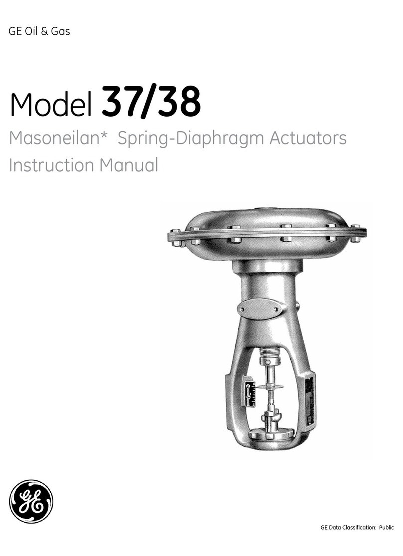
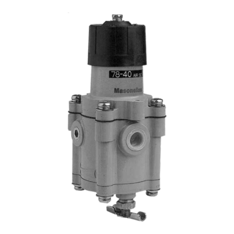
GE Becker VRP-SB-PID Series User manual

GE Oil & Gas
Becker*
VRP-SB-PID Series
Natural Gas Controllers
Instruction Manual
GE Data Classification : Public

Becker VRP-SB-PID Series Natural Gas Controllers Instruction Manual | b
© 2016 General Electric Company. All rights reserved.
THESE INSTRUCTIONS PROVIDE THE CUSTOMER/OPERATOR WITH IMPORTANT PROJECT-SPECIFIC
REFERENCE INFORMATION IN ADDITION TO THE CUSTOMER/OPERATOR’S NORMAL OPERATION
AND MAINTENANCE PROCEDURES. SINCE OPERATION AND MAINTENANCE PHILOSOPHIES VARY,
GE (GENERAL ELECTRIC COMPANY AND ITS SUBSIDIARIES AND AFFILIATES) DOES NOT ATTEMPT TO
DICTATE SPECIFIC PROCEDURES, BUT TO PROVIDE BASIC LIMITATIONS AND REQUIREMENTS CREATED
BY THE TYPE OF EQUIPMENT PROVIDED.
THESE INSTRUCTIONS ASSUME THAT OPERATORS ALREADY HAVE A GENERAL UNDERSTANDING OF THE
REQUIREMENTS FOR SAFE OPERATION OF MECHANICAL AND ELECTRICAL EQUIPMENT IN POTENTIALLY
HAZARDOUS ENVIRONMENTS. THEREFORE, THESE INSTRUCTIONS SHOULD BE INTERPRETED AND
APPLIED IN CONJUNCTION WITH THE SAFETY RULES AND REGULATIONS APPLICABLE AT THE SITE
AND THE PARTICULAR REQUIREMENTS FOR OPERATION OF OTHER EQUIPMENT AT THE SITE.
THESE INSTRUCTIONS DO NOT PURPORT TO COVER ALL DETAILS OR VARIATIONS IN EQUIPMENT NOR
TO PROVIDE FOR EVERY POSSIBLE CONTINGENCY TO BE MET IN CONNECTION WITH INSTALLATION,
OPERATION OR MAINTENANCE. SHOULD FURTHER INFORMATION BE DESIRED OR SHOULD PARTICULAR
PROBLEMS ARISE WHICH ARE NOT COVERED SUFFICIENTLY FOR THE CUSTOMER/OPERATOR’S
PURPOSES THE MATTER SHOULD BE REFERRED TO GE.
THE RIGHTS, OBLIGATIONS AND LIABILITIES OF GE AND THE CUSTOMER/OPERATOR ARE STRICTLY
LIMITED TO THOSE EXPRESSLY PROVIDED IN THE CONTRACT RELATING TO THE SUPPLY OF THE
EQUIPMENT. NO ADDITIONAL REPRESENTATIONS OR WARRANTIES BY GE REGARDING THE EQUIPMENT
OR ITS USE ARE GIVEN OR IMPLIED BY THE ISSUE OF THESE INSTRUCTIONS.
THESE INSTRUCTIONS ARE FURNISHED TO THE CUSTOMER/OPERATOR SOLELY TO ASSIST IN THE
INSTALLATION, TESTING, OPERATION, AND/OR MAINTENANCE OF THE EQUIPMENT DESCRIBED. THIS
DOCUMENT SHALL NOT BE REPRODUCED IN WHOLE OR IN PART WITHOUT THE WRITTEN APPROVAL
OF GE.

1 | GE Oil & Gas © 2016 General Electric Company. All rights reserved.
Introduction
GE’s Becker VRP-SB-PID series Natural Gas Controller
represents a breakthrough in pressure control technology for the
natural gas industry. Built to exacting specifications, this easily
maintained unit offers highly accurate control in a broad range
of operating environments. In addition to minimizing bleed gas,
the VRP-SB-PID series controllers are designed such that their
bleed gas can be routed to a lower pressure fuel gas system,
eliminating atmospheric bleed gas completely. The elimination
of this expensive bleed gas ultimately saves a significant
amount of money for the operating company and reduces
the environmental impact of atmospheric hydrocarbons,
and diminishing natural resources.
Your VRP-SB-PID controller will come factory adjusted for
your particular application. The use of the adjustment
procedures in this manual will only become necessary upon
installation of a rubber goods replacement kit, or any other
disassembly or reassembly of the controller.
Description
The Becker VRP-SB-PID is a proportional-integral-derivative
controller. This concept will be further explained in the
operations section of this manual. The VRP-SB-PID can
operate as a controller working in tandem with a positioner.
It can also operate as a high-pressure controller, controlling
a single acting actuator without the need for a positioner.
Another advantage of the VRP-SB-PID is its versatility.
With a few adjustments the VRP-SB-PID can be transformed
into a proportional plus derivative controller or VRP-SB-PD.
In VRP-SB-PD mode the controller can be used for highly
unstable systems for example, double stage cuts.
Table of Contents
Page Page
Introduction......................................................................................................... 1
Description........................................................................................................... 1
Scope of this Manual.......................................................................................... 2
Technical Assistance.......................................................................................... 2
Technical Information........................................................................................ 2
Principles of Operation...................................................................................... 4
Control Spring Range Selection for VRP-SB-PID Controllers.................6
Conversion to VRP-SB-PD Controller: ...............................................................9
Control Spring Range Selection for VRP-SB-PD Controllers ............... 10
PID-40, PID-80, PID-125 Explanations........................................................... 11
Adjustment Procedure.....................................................................................11
Applications.......................................................................................................13
Power Plant Control Station with Start-up/Trimming Regulator .... 14
Power Plant Station with Globe Style Control Valve............................... 15
Power Plant Station with T-Ball Style Control Valve .............................. 16
Power Plant Station with Globe Style Control Valve
and Globe Valve Trim............................................................................................ 17
Power Plant Station with Globe Style Control Valve ............................. 18
Fuel Regulator to Compressor Turbine......................................................... 19
Double Stage Cut with Working Monitor &
Two Proportional Controllers Only.................................................................. 20
Annual Maintenance Checklist ......................................................................21
Parts Lists and Part Numbers .......................................................................22
Accessories ........................................................................................................27
Assembly Manual..............................................................................................28
Top Body Assembly ............................................................................................... 28
Bottom Body Assembly ....................................................................................... 28
Top Body Piston Assembly ................................................................................ 30
Bottom Body Piston Assembly ......................................................................... 30
Top Body Diaphragm Assembly ...................................................................... 31
Bottom Body Diaphragm Assembly .............................................................. 31
Sensitivity Drum Assembly ................................................................................ 32
Centering the Diaphragms ................................................................................ 33
Sensitivity Spacer Assembly ............................................................................. 34
Bottom Cap Assembly ......................................................................................... 35
Bracket Mounting .................................................................................................. 36
Diaphragm Assembly #1 .................................................................................... 37
Diaphragm Assembly #2 .................................................................................... 37
Diaphragm Assembly #3 .................................................................................... 37
Spring Support Plate Assembly ....................................................................... 38
Feedback Chamber Assembly ......................................................................... 38
Spring Cartridge Assembly ................................................................................ 40
Adjusting Screw Assembly ................................................................................ 42
Spring Chamber Assembly ................................................................................ 43
Cap Assembly .......................................................................................................... 45
Appendix A - List of Recommended Tools....................................................47
Appendix B - Parts Silhouettes.......................................................................48
Bolts and Washers ................................................................................................. 48
Washers and Nuts.................................................................................................. 49
Diaghragm ................................................................................................................. 50
O-Rings......................................................................................................................... 51
Becker VRP-SB-PID Series Natural Gas Controllers Instruction Manual | 2© 2016 General Electric Company. All rights reserved.
Scope of this Manual
This manual provides information on operation principles,
applications, installation, adjustment, and maintenance of the
VRP-SB-PID. For information concerning actuators, valves, and
accessories, refer to the instruction manuals provided with the
specific product.
Note: Only those qualified through training or experience should
install, operate, or maintain Becker controllers. If there are any
questions concerning these instructions, contact your sales
representative, sales office, or manufacturer before proceeding.
Technical Assistance
Should you have any questions, please contact your local GE sales
representative or technical assistance at:
GE Oil & Gas
Attn: Becker Control Valves Technical Assistance
12970 Normandy Boulevard
Jacksonville, FL 32221
USA
Tel. +1-844-VALVE-GE
www.geoilandgas.com/valves
Technical Information
Table 1: Technical Specifications
Technical Specifications
Maximum Control
Pressure
1500 psig
10,342 kPa
Power Gas Requirements Dry, filtered (40 micron) gas. Sufficient
pressure to operate positioner or actuator
Power Gas Maximum
Pressure
40, 80, 125 psig
Bleed to Pressure System
(BPS)
25 psig maximum
Output Signal Three models are available depending
on the maximum power gas pressure.
40, 80 and 125 psig.
Output Capacity 1.5 Cv maximum
Action Direct and reverse acting
Control Accuracy 3/4% of setpoint pressure
Resolution 0.2% of setpoint pressure
Operative Ambient
Temperature Range
-20°F to 160°F
-29°C to 71° C
Steady State Gas
Consumption
Zero
Approximate Weight 20 pounds
9kg
Pressure Connections 1/4 inch female NPT
Housing Meets NEMA 3 Classification (Weather
tight)
Installation Orientation Controller should be installed in the
vertical position
Model Number
The VRP-SB-PID model number is an alphanumeric combination,
which characterizes your specific unit. This number can be found
on the name tag located on the spring cartridge.
Example: VRP-600-SB-PID-40
VRP = Valve Regulator Pilot/Controller
600 = Maximum allowable control pressure
SB = Single Acting
PID = Proportional, Integral, Derivative Control
40 = Maximum power gas
Each unit has a stainless steel control tag fastened under one
of the bolts of the spring cartridge. The range of the control
spring is stamped on the face side of the tag. The shipping date
and seven-character part number are stamped on the bottom
side of the tag.
Table 2: Materials of Construction
Materials of Construction
External Parts Anodized 2024 aircraft alloy aluminum(1)
Internal Parts 316 stainless steel and 2024 anodized aluminum
Springs Alloy Steel
Diaphragms Buna-N reinforced by nylon fabric
Seats and O-Rings Buna-N
Tubing 316 stainless steel
Fittings 316 stainless steel
Gauges 2-1/2 inch dial liquid filled stainless steel
connection w/stainless steel case
(1) All stainless steel external construction available.
Exterior or corrosion resistant coating also available.
Example
A. Typical spring + diaphragm actuator w/ Globe Valve.
Power gas = 40 psig max.
Typical bench set 11 to 23
BPS available up to 5 psig (fuel system or low
pressure distribution)
B. Typical spring + piston actuator.
Power gas = 150 psi max. with BPS = 25 psig max.

3 | GE Oil & Gas © 2016 General Electric Company. All rights reserved.
Figure 1 - Principles of Operation
Direct Acting VRP-600-SB-PID-40 (High Gain) Yellow Spring
“False Signal”
Needle Valve
Output
Orifice
(Derivative)
P4 P3
Output
Block
Valve
Sensing
Pressure
P1
P1 P2
P4 P3
P2
Metering Valve
(Integral)
Power
Gas
Top Balance Valve
In the case of a
decrease in sensing
pressure, the bottom
balance valve will open
and the controller will
bleed gas.
Figure 1B
Figure 1CFigure 1D
Figure 1A
Bottom Balance Valve
The arrows in Figure 1A represent
the steady state or “balanced”
condition where the spring force
and force on the sensing diaphragm
are equal. If the sensing pressure
increases, the net force on the
sensing diaphragm is down. If the
sensing pressure decreases, the
net force on the diaphragm is up.
When spring and sensing diaphragm
forces are equal to each other, the
controller is balanced, and at steady
state. In the additional diagrams (1C,
1D) the dynamics of balance valves
for a decrease in setpoint is shown.
A high gain controller uses small
rings (shown in Figure 1B). Middle
gain controllers use large rings
(shown below). Low gain pilots use
no rings.
The derivative function is
introduced by applying a
portion of the output signal to
the bottom of the feed-back
diaphragm. The orifice is
adjusted to ensure system
stability. The integral function
is introduced by applying a
portion of the output signal
to the top of the feedback
diaphragm. The metering valve
provides adjustability of reset
rate.
In the case of a decrease
in sensing pressure, the
top balance valve closes,
and cuts off the power
gas. Arrows in figures
1C and 1D represent the
direction of gas flow.

Becker VRP-SB-PID Series Natural Gas Controllers Instruction Manual | 4© 2016 General Electric Company. All rights reserved.
Principles of Operation
Direct Acting VRP-SB-PID Controller (Figure 2)
When the measured variable pressure (sensing pressure) is
equal to the setpoint, the net force on the sensing diaphragm
is zero. This is the equilibrium or “balanced” condition where the
sensing pressure that pushes down on the sensing diaphragm,
and the spring force that pulls up on the sensing diaphragm are
equal. From this position two possible scenarios can occur, the
sensing pressure can rise above or below the setpoint.
If the sensing pressure rises above the setpoint the net force
on the sensing diaphragm is downward. The bottom balance
valve will close. The top balance valve opens, increasing the
flow of power gas to the output port. The combination of these
actions creates a rise in output pressure. When the sensing
pressure falls below the setpoint the net force on the sensing
diaphragm is upward. Now the top balance valve will close.
The bottom balance valve opens, increasing the flow of
gas to the exhaust port. The combination of these actions
decreases the output pressure.
In order to control how much gas passes through the balance
valve, the output pressure is fed back to the bottom side of a
diaphragm within the feedback module. As the output pressure
increases, this feedback pressure closes the inlet balance valve.
As the output pressure decreases, this feedback pressure
decreases, closing the exhaust balance valve. This feedback
force is such that the output pressure will change proportionally
with the deviation of the sensing pressure from the setpoint,
which gives us a proportional response.
By restricting the flow of the output pressure to the bottom side
of the feedback diaphragm, a derivative function is introduced.
This is accomplished with an adjustable orifice that controls the
flow to the bottom side of the feedback diaphragm. This orifice
delays the feedback force, allowing the output to change quickly
in response to a quick change in the system. Slow changes in
the system; however, are less affected by the derivative orifice
because the output pressure has time to equalize on both sides
of the orifice. The adjustability of the orifice allows us to optimize
the system. If the restriction is too great, the feedback delay will
be too long and the system will become unstable.
It is already established that the change in output pressure
is proportional to the deviance of the sensing pressure.
Because of this, a sensing pressure that is not at the setpoint
is required to maintain a particular change in output pressure.
The difference between the setpoint and the maintained
pressure at a particular output pressure is the “offset”. This
offset can be eliminated over time by allowing the top side
of the feedback diaphragm to slowly equalize with the bottom
side. By using a metering valve to control the flow to the top
side of the feedback diaphragm we introduce our integral
function. This adjustment also allows us to optimize the system.
If the top side of the diaphragm equalizes with the bottom side
too quickly, the feedback function providing proportionality is
cancelled out and control will become unstable.
Reverse Acting VRP-SB-PID Controller (Figure 3)
In this case, the power gas is fed through the bottom balanced
valve instead of the top. The exhaust now vents from the top
balanced valve, and use of the feedback chamber is reversed.
This simply means that the adjustable orifice controls the flow
to the top feedback chamber, and the metering valve controls
the flow to the bottom feedback chamber.
If the sensing pressure rises above the setpoint then the net
force on the sensing diaphragm is down. The bottom balanced
valve will close. The top balanced valve opens, allowing gas
to vent through the exhaust port. The combination of these
actions results in a decrease in output pressure. If the sensing
pressure falls below the setpoint, the net force on the diaphragm
is upward. The bottom balanced valve opens, increasing the
flow of power gas to the output. The top balanced valve will
close. This combination creates a rise in output pressure.
As the name implies, the dynamics are completely “reversed”
from the direct acting configuration. The same can be said about
the feedback chamber dynamics. The output pressure is now fed
into the top side of the feedback diaphragm, while elimination of
the “offset” is accomplished by feeding the output pressure to
the bottom side of the feedback diaphragm.

5 | GE Oil & Gas © 2016 General Electric Company. All rights reserved.
Sensing
Pressure
Integral
Derivative
Output
Derivative
Integral
Output
Output
Block Valve
Exhaust
P2
4P3P
P1
P4 P3
P2
P1
Feedback
Module
Power
Gas
Exhaust
Sensing
Pressure
Figure 2 - Direct Acting VRP-SB-PID Figure 3 - Reverse Acting VRP-SB-PID

Becker VRP-SB-PID Series Natural Gas Controllers Instruction Manual | 6© 2016 General Electric Company. All rights reserved.
Control Spring Range Selection for VRP-SB-PID Controllers
Table 3 - Control Spring Range Selection for VRP-SB-PID-40
VRP-SB-PID
Model No.
Control Range
(pisg/kPa)
Spring Color
(Part
Number)
Proportional Band with 3-15 psig
(21-103 kPa) Output
Setpoint
Change per
Revolution of
Setpoint Screw
(psig/kPa)
Setpoint
Range Discreet
Remote Control
(SM-1100)
Setpoint
Range Analog
(4-20 mA)
Remote Control
(SM-1000)
No Rings Large
Rings
Small
Rings
VRP-600-SB-PID-40 35-60 psig
(241-414 kPa)
Gold
(25-8236)
51 pisg
(352 kPa)
36 psig
(248 kPa)
23 pisg
(159 kPa)
2.1 psig
(14.5 kPa)
11.6 psig
(80 kPa)
25 psig
(172 kPa)
45-135 psig
(310-931 kPa)
Beige
(25-8238)
7.4 psig
(51 kPa)
41 psig
(283 kPa)
90 psig
(631 kPa)
70-195 psig
(483-1345 kPa)
Burgundy
(25-8239)
11.3 pisg
(78 kPa)
62 psig
427 kPa)
125 psig
(862 kPa)
155-320 psig
(1069-2206 kPa)
Pink
(25-8240)
24 psig
(165 kPa)
132 psig
(910 kPa)
165 psig
(1138 kPa)
295-600 psig
(2034-4137 kPa)
Yellow
(25-1306)
85 psig
(586 kPa)
405 psig
(2792 kPa)
405 psig
(2792 kPa)
VRP-1000-SB-PID-40 115-300 psig
(793-2275 kPa)
Burgundy
(25-8239)
87 psig
(600 kPa)
61 psig
(421 kPa)
39 psig
(270 kPa)
19.2 psig
(132 kPa)
106 psig
(731 kPa)
215 psig
(1482 kPa)
260-540 psig
(1793-3723 kPa)
Pink
(25-8240
41 psig
(283 kPa)
226 psig
(1558 kPa)
280 psig
(1931 kPa)
500-1000 psig
(3447-6895 kPa)
Yellow
(25-1306)
143 psig
(989 kPa)
680 pisg
(4688 kPa)
680 pisg
(4688 kPa)
VRP-1500-SB-PID-40 800-1300 psig
(5654-8964 kPa)
Grey
(25-1562 87 psig
(600 kPa)
61 psig
(421 kPa)
39 psig
(270 kPa)
227 psig
(1565 kPa)
830 psig
(5723 kPa)
830 psig
(5723 kPa)
900-1500 psig
(6205-10342 kPa)
Violet
(25-8073)
276 psig
(1903 kPa)
930 psig
(6412 kPa)
930 psig
(6412 kPa)
Repair Kit #30-9301 for VRP-600
Repair Kit #30-9307 for VRP-1000/1500
Sample Controller Gain Calculation:
VRP-600-SB-PID-40, High Gain (Small Rings), Yellow Spring
Controller Gain (K) =Output Range(1) =12 psig =0.522
Proportional Band 23 psig
(1)Output Range 30 psig - 6 psig = 24 psig (165 kPa)

7 | GE Oil & Gas © 2016 General Electric Company. All rights reserved.
Table 4 - Control Spring Range Selection for VRP-SB-PID-80
VRP-SB-PID
Model No.
Control Range
(pisg/kPa)
Spring Color
(Part
Number)
Proportional Band with 6-30 psig
(41-207 kPa) Output
Setpoint
Change per
Revolution of
Setpoint Screw
(psig/kPa)
Setpoint
Range Discreet
Remote Control
(SM-1100)
Setpoint
Range Analog
(4-20 mA)
Remote Control
(SM-1000)
No Rings Large
Rings
Small
Rings
VRP-600-SB-PID-80
70-160 psig
(483-1103 kPa)
Beige
(25-8238)
102 pisg
(703 kPa)
72 psig
(496 kPa)
46 pisg
(317 kPa)
7.4 psig
(51 kPa)
41 psig
(281 kPa)
90 psig
(621 kPa)
95-220 psig
(655-1517 kPa)
Burgundy
(25-8239)
11.3 psig
(78 kPa)
62 psig
(429 kPa)
125 psig
(862 kPa)
180-345 psig
(1241-2379 kPa)
Pink
(25-8240)
24 pisg
(165 kPa)
132 psig
(910 kPa)
165 psig
(1138 kPa)
320-600 psig
(2206-4137 kPa)
Yellow
(25-1306)
85 psig
(586 kPa)
380 psig
(2620 kPa)
380 psig
(2620 kPa)
VRP-1000-SB-PID-80
155-370 psig
(1069-2551 kPa)
Burgundy
(25-8239)
174 psig
(1200
kPa)
122 psig
(841 kPa)
78 psig
(538 kPa)
19.2 psig
(132 kPa)
106 psig
(728 kPa)
215 psig
(1482 kPa)
300-580 psig
(2069-4000 kPa)
Pink
(25-8240)
41 psig
(283 kPa)
226 psig
(1558 kPa)
280 psig
(1931 kPa)
540-1000 psig
(3723-6895 kPa)
Yellow
(25-1306)
143 psig
(989 kPa)
680 pisg
(4516 kPa)
680 pisg
(4516 kPa)
VRP-1500-SB-PID-80
860-1300 psig
(5930-8964 kPa)
Grey
(25-1562) 87 psig
(600 kPa)
61 psig
(421 kPa)
39 psig
(270 kPa)
227 psig
(1565 kPa)
805 psig
(5550 kPa)
805 psig
(5550 kPa)
960-1500 psig
(6619-10342 kPa)
Violet
(25-8073)
276 psig
(1903 kPa)
905 psig
(6240 kPa)
905 psig
(6240 kPa)
Repair Kit #30-9301 for VRP-600
Repair Kit #30-9307 for VRP-1000/1500
Sample Controller Gain Calculation:
VRP-600-SB-PID-80, Low Gain (No Rings), Yellow Spring
Controller Gain (K) =Output Range(1) =24 psig =0.235
Proportional Band 102 psig
(1)Output Range 30 psig - 6 psig = 24 psig (165 kPa)

Becker VRP-SB-PID Series Natural Gas Controllers Instruction Manual | 8© 2016 General Electric Company. All rights reserved.
Table 5 - Control Spring Range Selection for VRP-SB-PID-125
VRP-SB-PID
Model No.
Control Range
(pisg/kPa)
Spring Color
(Part
Number)
Proportional Band with 40-70 psig
(276-483 kPa) Output
Setpoint
Change per
Revolution of
Setpoint Screw
(psig/kPa)
Setpoint
Range Discreet
Remote Control
(SM-1100)
Setpoint
Range Analog
(4-20 mA)
Remote Control
(SM-1000)
No Rings Large
Rings
Small
Rings
VRP-600-SB-PID-125
115-195 psig
(793-1345 kPa)
Beige
(25-8238)
127.5 psig
(879 kPa)
90 psig
(621 kPa)
57.5 psig
(396 kPa)
7.4 psig
(51 kPa)
41 psig
(281 kPa)
90 psig
(621 kPa)
130-225 psig
(896-1758 kPa)
Burgundy
(25-8239)
11.3 psig
(78 kPa)
62 psig
(429 kPa)
125 psig
(862 kPa)
215-380 psig
(1482-2620 kPa)
Pink
(25-8240)
24 psig
(164 kPa)
132 psig
(910 kPa)
165 psig
(1138 kPa)
355-600 psig
(2448-4137 kPa)
Yellow
(25-1306)
85 psig
(586 kPa)
345 psig
(2379 kPa)
345 psig
(2379 kPa)
VRP-1000-SB-PID-125
215-430 psig
(1482-2967 kPa)
Burgundy
(25-8239)
217.5 psig
(1500
kPa)
52 psig
(1051
kPa)
97.5 psig
(672 kPa)
19.2 psig
(132 kPa)
106 psig
(728 kPa)
215 psig
(1482 kPa)
360-640 psig
(2482-4413 kPa)
Pink
(25-8240)
41 psig
(283 kPa)
226 psig
(1558 kPa)
280 psig
(1931 kPa)
600-1000 psig
(4137-6895 kPa)
Yellow
(25-1306)
143 psig
(989 kPa)
620 pisg
(4275 kPa)
620 pisg
(4275 kPa)
VRP-1500-SB-PID-125
920-1300 psig
(6343-8964 kPa)
Grey
(25-1562) 217.5 psig
(1500
kPa)
52 psig
(1051
kPa)
97.5 psig
(672 kPa)
227 psig
(1565 kPa)
770 psig
(5309 kPa)
770 psig
(5309 kPa)
1020 -1500 psig
(7033-10342 kPa)
Violet
(25-8073)
276 psig
(1903 kPa)
870 psig
(5998 kPa)
870 psig
(5998 kPa)
Repair Kit #30-9301 for VRP-600
Repair Kit #30-9307 for VRP-1000/1500
Sample Controller Gain Calculation:
VRP-600-SB-PID-125, Low Gain (No Rings), Yellow Spring
Controller Gain (K) =Output Range(1) =30 psig =0.235
Proportional Band 127.5 psig
(1)Output Range 30 psig - 6 psig = 24 psig (165 kPa)

9 | GE Oil & Gas © 2016 General Electric Company. All rights reserved.
Conversion to VRP-SB-PD Controller:
For highly unstable systems it may be necessary to convert the VRP-SB-PID into a VRP-SB-PD controller. In this case the controller will
have a permanent offset due to an absence of the integral function.
Figure 4 - Direct Acting VRP-SB-PID Controller Figure 5 - Reverse Acting VRP-SB-PID Controller
Power
Gas
Exhaust
Vent
Output
Output
Integral
(Full Closed) Integral
(Full Closed)
Derivative
Output
Block Valve
Sensing
Pressure
Sensing
Pressure
Vent replaces
the plug
Derivative
Output
Block Valve
Feedback
Module
Power gas is fed
into the integral
chamber
P4
1P 2P
P3
P1
P3P4
P2

Becker VRP-SB-PID Series Natural Gas Controllers Instruction Manual | 10© 2016 General Electric Company. All rights reserved.
Control Spring Range Selection for VRP-SB-PD Controllers
Table 6 - Control Spring Range Selection for VRP-SB-PD-40 Direct-Acting and Reverse-Acting Controller
VRP-SB-PD
Model No.
Spring
Color
(Part
Number)
No Rings
Low Gain
Large Rings
Medium Gain
Small Rings
High Gain Setpoint
Change per
Revolution
of setpoint
screw
(psig/kPa)
Control Range
(psig/kPa)
Proportional
Band w/3-15
psig (21-103
kPa) Output
Control Range
(psig/kPa)
Proportional
Band w/3-15
psig (21-103
kPa) Output
Control Range
(psig/kPa)
Proportional
Band w/3-15
psig (21-103
kPa) Output
VRP-600-SB-
PD-40
Beige
(25-8238)
100-150 psig
(689-1034 kPa)
51 psig
(352 kPa)
90-150 psig
(621-1034 kPa)
36 psig
(248 kPa)
75-140 psig
(517-965 kPa)
23 psig
(159 kPa)
7.4 psig
(51 kPa)
Burgundy
(25-8239)
130-220 psig
(689-1034 kPa)
110-200 psig
(758-1379 kPa)
100-200 psig
(689-1379 kPa)
11.3 psig
(78 kPa)
Pink
(25-8240)
230-350 psig
(1586-2413 kPa)
200-340 psig
(1379-2344 kPa)
180-330 psig
(1241-2275 kPa)
24 psig
(165 kPa)
Yellow
(25-1306)
350-600 psig
(2413-4137 kPa)
330-600 psig
(2275-4137 kPa)
320-600 psig
(2206-4137 kPa)
85 psig
(568 kPa)
VRP-1000-
SB-PD-40
Beige
(25-8238)
180-350 psig
(1241-1724 kPa)
87 psig
(600 kPa)
150-250 psig
(1034-1724 kPa)
61 psig
(421 kPa)
120-230 psig
(827-1586 kPa)
39 psig
(270 kPa)
12.6 psig
(87 kPa)
Burgundy
(25-8239)
220-350 psig
(1517-2413 kPa)
200-350psig
(1379-2413 kPa)
160-340 psig
1103-2344 kPa)
19.2psig
(132 kPa)
Pink
(25-8240)
350-590 psig
(2413-4068 kPa)
340-570 psig
(2344-3930 kPa)
310-550 psig
(2137-3792 kPa)
41 psig
(283 kPa)
Yellow
(25-1306)
590-1050 psig
(4068-7239 kPa)
570-1050 psig
(3930-7239 kPa)
550-1050 psig
3792-7239 kPa)
143 pisg
(986 kPa)
VRP-1500 -
SB-PD-40
Grey
(25-1562)
900-1350 psig
(6205-9308 kPa) 87 psig
(600 kPa)
850-1350 psig
(5861-9308 kPa) 61 psig
(421 kPa)
850-1350 psig
(5861-9308 kPa) 39 psig
(270 kPa)
227 psig
(1565 kPa)
Violet
(25-8073)
1000-1500 psig
(6895-10342 kPa)
950-1500 psig
(6550-10342 kPa)
950-1500 psig
(6550-10342 kPa)
276psig
(1903 kPa)
Note: Refer to motor information specified in Tables 3 and 4.
Table 7 - Control Spring Range Selection for VRP-SB-PD-80 Direct-Acting and Reverse-Acting Controller
VRP-SB-PD
Model No.
Spring
Color
(Part
Number)
No Rings
Low Gain
Large Rings
Medium Gain
Small Rings
High Gain Setpoint
Change per
Revolution
of setpoint
screw
(psig/kPa)
Control Range
(psig/kPa)
Proportional
Band w/6-30
psig (41-207
kPa) Output
Control Range
(psig/kPa)
Proportional
Band w/6-30
psig (41-207
kPa) Output
Control Range
(psig/kPa)
Proportional
Band w/6-30
psig (41-207
kPa) Output
VRP-600-
SB-PD-80
Beige
(25-8238) N/A
102 psig
(703 kPa)
N/A
72 psig
(496 kPa)
N/A
46 psig
(317 kPa)
7.4 psig
(51 kPa)
Burgundy
(25-8239) N/A 180-260 psig
(1241-1793 kPa)
150-250 psig
(1034-1724 kPa)
11.3 psig
(78 kPa)
Pink
(25-8240)
300-400 psig
(2068-2758 kPa)
250-390 psig
(1724-2689 kPa)
340-370 psig
(1655-2551 kPa)
24 psig
(165 kPa)
Yellow
(25-1306)
400-600 psig
(2758-4137 kPa)
380-600 psig
(2620-4137 kPa)
370-600 psig
(2551-4137 kPa)
85 psig
(568 kPa)
VRP-1000-
SB-PD-80
Beige
(25-8238) N/A
174 psig
(1200 kPa)
N/A)
122 psig
(841 kPa)
200-300 psig
(1379-2086 kPa)
78 psig
(538 kPa)
12.6 psig
(87 kPa)
Burgundy
(25-8239) N/A 310-430 psig
(1379-2413 kPa)
250-400 psig
1724-2758 kPa)
19.2psig
(132 kPa)
Pink
(25-8240)
500-700 psig
(3447-4826 kPa)
430-660 psig
(2965-4551 kPa)
400-630 psig
(2758-4344 kPa)
41 psig
(283 kPa)
Yellow
(25-1306)
700-1050 psig
(4826-7239 kPa)
650-1050 psig
(4482-7239 kPa)
620-1050 psig
4275-7239 kPa)
143 pisg
(986 kPa)
VRP-1500 -
SB-PD-80
Grey
(25-1562)
1000-1350 psig
(6895-9308 kPa) 174 psig
(1200 kPa)
1000-1350 psig
(6895-9308 kPa) 122 psig
(841 kPa)
950-1350 psig
(6550-9308 kPa) 78 psig
(538 kPa)
227 psig
(1565 kPa)
Violet
(25-8073)
1100-1500 psig
(7584-10342 kPa)
1100-1500 psig
(7584-10342 kPa)
1050-1500 psig
(7239-10342 kPa)
276psig
(1903 kPa)
Note: Refer to motor information specified in Tables 3 and 4.

11 | GE Oil & Gas © 2016 General Electric Company. All rights reserved.
PID-40, PID-80, PID-125 Explanations
Why a PID-40, PID-80, or PID-125? To understand the reason
why there are different PID models for higher power gas
pressures, we must understand the concept of the “floating”
diaphragm.
In the VRP-SB-PID feedback chamber there is a feedback
diaphragm that introduces the feedback force to the controller.
A closer look at the mechanisms that hold the diaphragm in
place would show that it is “floating” - or not truly connected to
the spring chamber or VRP-SB-CH body. The diaphragm works
by transmitting forces through pistons that are connected to the
spring chamber and VRP-SB-CH body. The only thing holding this
diaphragm in place are the compressive forces from the spring
chamber and VRP-SB-CH body. If we attempt to put 125 psig
power gas through into a PID-40 there would not be enough
of a compressive force to hold the feedback diaphragm in
place, and it would separate. For the PID-40, the pressure
that would cause this separation is 54 psig. For the PID-80
and PID-125, the pressures that cause separation are 100 psig,
and 150 psig respectively.
This is an interesting phenomenon because if the diaphragm
separates that doesn’t mean the PID is damaged. All separation
does is cause the controller to lock up, and cease operation. Upon
change to the correct power gas, the controller will return to
functioning completely normally with no damage to the parts.
In order to keep the diaphragm in the feedback chamber
functioning properly, different springs are introduced into the
bottom cap of the PID. These springs provide a different counter
balance compressive forces that keep the feedback diaphragm
operational. However, the stronger the spring inserted into the
bottom cap of the PID, the less sensitive the PID becomes. There
is a small trade-off involved, stronger springs such as the one
in the bottom cap of the VRP-SB- PID-125 can handle the power
gas for the higher pressure applications, but the minimum
setpoint for control is also higher.
The springs in the bottom cap were designed according to
the specifications of typical applications of the PID. One such
example is the standard low pressure spring and diaphragm
actuator application. The typical diaphragm rating for this kind
of actuator is 40 psig, so a VRP-SB-PID-40 is an excellent fit for
this application. The reason being, a VRP-SB-PID-40 has a
maximum power gas of 40 psig, and the spring in the bottom
cap is designed such that it provides the perfect counter balance
force to keep the “floating” diaphragm operating correctly.
For the VRP-SB-PID-80 there are higher pressure applications
such as the Welker Jet Regulator, or high pressure spring and
diaphragm actuators. And for even higher pressure applications
such as ball valves, the pressure needed to control can be
as much as 125 psig. In this case, the model VRP-SB-PID-125
would be an excellent choice. In each of these higher pressure
applications, the springs in the bottom cap of both the VRP-SB-
PID-80 and VRP-SB-PID-125, are designed specifically for the
purpose of keeping the “floating” diaphragm compressed and
fully functional. Refer to page 27 for part numbers and section
views of the 40, 80, and 125 bottom cap configurations.
Adjustment Procedure
1. Dead Band Adjustment
This adjustment is done by converting a VRP-SB-PID controller to
a VRP-SB-CH controller.
A. Adjust supply regulator to desired pressure. The last digits
in the model number represent the maximum supply gas for
that model PID. Supply pressure should be set according to
last digits in the model number, but it can be less than the
maximum. For example, a PID-40 should have the supply
pressure set at 40 psig (276 kPa), and a PID-125 should
have supply pressure set at 125 psig (862 kPa). However,
if the supply pressure to a PID-40 is 30 psig (207 kPa), that
is acceptable, as long as the supply pressure does not go
above 40 psig (276 kPa).
B. Close valve on measured variable line. Adjust measured
variable in sensing chamber to the desired setpoint using
false signal valves on the spring chamber.
C. Turn adjusting screw counterclockwise until it will not turn
anymore. Do not force adjusting screw.
Close Output
Block Valve
P2
P4 P3
P1
Figure 6 - Output Block Valve
D. Close output block valve (figure 6). Open integral (metering)
valve, and derivative orifice to 6 (wide open).
E. Remove tubing which connects integral and derivative orifices.
F. If this is the first time that the unit is being adjusted after
assembly, firstly remove the locking set screw from the
radial hole in the adjustment drum. This may require the
drum to be rotated until the hole containing the set screw
can be accessed.
G. Turn sensitivity drum to the right as far as it will go (in the
direction of increasing numbers). Then turn the drum one
complete rotation to the left. Use the numbers on the drum
as a guide (i.e. if you turn to the right and it stops on “7” then
turn it back to the left until it rotates back to “7”).
H. For a direct acting controller, turn the adjusting screw
clockwise until the output gauge pressure just begins to
decrease, then stop turning. At this point the gauge may
decrease all the way to zero very quickly.
For a reverse acting controller turn the adjusting screw
clockwise until the output gauge pressure just begins to
increase then stop turning. At this point the gauge may
increase to the maximum power gas very quickly.

Becker VRP-SB-PID Series Natural Gas Controllers Instruction Manual | 12© 2016 General Electric Company. All rights reserved.
In either case (reverse or direct acting), a quick response
of the output needle suggests the sensitivity of the PID
still needs tuning.
I. For a direct acting controller, turn the sensitivity drum
to the right until the pressure just increases again. For a
reverse acting controller, turn the sensitivity drum to the left
until the pressure just decreases again.
J. Repeat steps H and I until output pressure is stationary
between atmospheric pressure and maximum power
gas pressure.
K. When the controller output is stationary between atmospheric
and power gas pressure, and the sensitivity drum is adjusted
such that any movement to the right would vent gas, the
controller is approximately at “zero” dead band. “Zero” dead
band is defined when a slow growing bubble (10-30 seconds)
is detected from the exhaust port. Make small adjustments in
adjustment drum until “zero” dead band condition is met.
L. To lock the deadband setting in place, insert the locking
set screw into one of the radial holes in the adjustment
drum. Using a torque wrench, torque to 1-2 inlb. Care
should be taken not to exceed this level, as if the screw is
over-tightened it may affect the calibration of the pilot. If a
torque wrench is not available then torque the screw just
enough so that it provides a light grip on the inner shaft.
Recheck the vent port on the controller.
M. Reconnect all tubing disconnected in step E. Refer to
Table 8 on page 13 for correct derivative orifice and
metering valve settings. Open the measured variable valve.
Open the output block valve in order to begin control and
make fine adjustments.
2. Proportional Band Test
The purpose of this test is to check the proper operation of
the feedback chamber. Leaks, misalignments or wrong internal
parts can cause the PID to not function properly. The output
valve must stay open to allow output pressure to communicate
with the feedback chamber.
For a Direct Acting Controller:
The integral (top) chamber must be at atmospheric pressure.
A. Remove plug from integral chamber and close reset valve
(Figure 7). Tubing between derivative orifice and reset
metering valve should stay connected.
Close reset
valve
Plug
Feedback Module
Derivative
orifice
Remove this
plug
Figure 7 - Proportional Band Test
B. Change the sensing pressure until the output pressure is
approximately 30% away from the power gas. For example,
a VRP-PID- 40 needs the output adjusted to 30 psig, while a
VRP-PID-80 and VRP-PID-125 need outputs of 60 psig and
90 psig respectively.
C. Consult the appropriate table from pages 6-8 depending
on which model PID you have. Look at the left side of the
table for the correct model number. Associate that model
number with the corresponding control spring. Look at
the chart under “Proportional Band” and choose the
corresponding gain configuration of the PID. Look down for
the point where the model and control spring row intersects
with the proportional band/gain configuration column. This
number is the amount of sensing pressure that must be input
in order to see a 12 psig output change for a PID-40, 24 psig
output change for a PID-80, or 30 psig change for a PID-125.
Example of Step C:
VRP-600-SB-PID-40, direct acting, high gain, yellow control spring
1. Turn to page 6 and look in the left hand column to find
VRP-600-SB-PID-40.
2. The second column to the right shows the control spring
range, and the third column reads “yellow control spring,
25- 1306” for the model VRP-600-SB-PID-40.
3. “With Small Ring” for a high gain pilot.
4. Where the rows and columns intersect is “23 psig (159 kPa)”.
5. Take note of the initial sensing pressure and initial output
pressure. Change the sensing pressure 23 psig (159 kPa) from
the initial value. The output gauge should only have changed
12 psig (83 kPa) from its initial value.
D. Reinstall the top feedback chamber plug. Open the reset valve,
and check for leaks around the feedback module.
For a Reverse Acting Controller:
The integral (bottom) chamber must have full output pressure.
A. Adjust the sensing pressure such that the output is at full power
gas pressure. Wait a couple of minutes, and close the integral
valve. This locks full power gas pressure in the integral chamber.
B. Follow steps B and C for a direct acting controller.
C. Re-open the metering valve.
3. Controller Test in PID Mode
Isolate controller from the actuator by positioning MCV in manual
mode. The derivative orifice block should be set at 6. The power
gas should be the maximum allowed for your controller (i.e. a
PID-125 should have its power gas at 125 psig). The object of this
test is to make sure the output pressure reaches zero or max in
specified time.
This test is to be done once with the integral valve wide open, and
once with the integral valve at #7. This test requires a timer.
To check that the output pressure drops to zero in specified time:
Start the test with sensing pressure 20% above setpoint (i.e., if
the setpoint is 200 psig, raise it to 240 psig). The output pressure
should reach its maximum (equal to power gas). Allow the PID
chamber to become fully loaded by waiting 1-2 minutes. Lower
the sensing pressure to 3% of the maximum spring range below
the setpoint (i.e., if the setpoint is 200 psig, and the top of the
control spring’s range is 320 psig, set your pressure to 200 -
.03x320 = 190.4 pisg, approximately). Start your timer. The output
pressure should jump down a little and then continue to lower
steadily. Stop your timer when the output pressure has gone down
to approximately 10% of its full range (i.e., ˜12.5% for a PID-125).
This should take 10-20 seconds if the integral valve is wide open,
and 1-2 minutes if it is at #7.

13 | GE Oil & Gas © 2016 General Electric Company. All rights reserved.
To check that the output pressure rises to max in
specified time:
Start the test with sensing pressure 20% below setpoint (i.e.,
if the setpoint is 200 psig lower it to 160 psig). The output pressure
should fall to zero. Allow the PID chamber to empty by waiting
1-2 minutes. Raise the sensing pressure to 3% of the maximum
spring range above the setpoint (i.e., if the setpoint is 200 psig and
the top of the control spring’s range is 32 psig, set your pressure
to 200 + .03 x 320 = 209.6 psig, approximately) Start your timer.
The output pressure should jump up a little and then continue to
rise steadily. Stop your tier when the output pressure has risen to
approximately 90% of its full range (i.e. ˜112.5% for a PID-125).
This should take 10-20 seconds if the integral valve is wide open,
and 1-2 minutes if it is at #7.
4. Dead Band Adjustment Drum
VRP-SB-PID controllers are factory adjusted with “zero” dead
band. “Zero” dead band is defined such that when controller
is at steady state there is a small growing bubble (10-30 seconds)
from exhaust port. For some systems this dead band can be
changed. On the adjusting drum between each whole number
(large markings) are 3 small markings. Turning the adjusting
drum 1 marking to the right (in direction of increasing numbers)
decreases the dead band from “zero” to -1/4 (negative one-fourth)
and introduces a small bleed gas. This action will increase
controller sensitivity. Turning the adjusting drum 1 marking
to the left (in direction of decreasing numbers) increases the
dead band from “zero” to +1/4 (positive one-fourth). Another
example is +1/2 or –1/2 dead band. This simply means that from
the dead band “zero” setting the adjustment drum is moved
2 markings left (+1/2) or 2 markings right (-1/2). This important
terminology is useful when setting different PID models using
the example applications section (pages 15-20). After adjustment
is completed, tighten the set screw to a torque of 1-2 in-lb to lock
the deadband setting.
Changes in the dead band (sensitivity) adjustment affect
setpoint adjustments. Each mark represents a 1/44 rotation
of the adjusting screw. When dead band is decreased, (bleed
gas introduced) setpoint is decreased. When dead band is
increased, setpoint is increased. Using tables 3-5, refer to
setpoint change per revolution. To find out the setpoint
change divide the specified value by 44:
Example Calculation
VRP-600-SB-PID-40, yellow spring = 85 psig per revolution.
Each division on the drum represents 85/44 or 1.9 psig change
in setpoint.
Derivative Orifice
Refer to a recommended derivative orifice and controller gain
for your specific application. Derivative orifice can be adjusted
by turning between numbers 0 and 6. “0” represents the fastest
response of the controller and “6” the slowest. Three orifice sizes
are available: small (not marked), medium (marked “M”) and large
(marked “L”). Small orifice represents the fastest response, large
the slowest.
Integral (Reset) Valve
The reset metering valve can be adjusted between 4 and 15 on
the outer barrel. Four represents the smallest reset value (the
slowest correction rate).
Proportional Band Gain
Each model is available with three gains. The feedback module
can be used without rings for the highest proportional band or
with sets of rings. Middle gain controllers use large rings in the
feedback chamber and high gain controllers use small rings.
By referring to the spring range charts on pages 7 - 9, along
with initial settings from table 8, the desired proportional band
is selected. This selection determines which gain rings are
needed if any. Controllers are normally shipped with high
gain rings.
Applications
The Becker VRP-SB-PID configurations and their operative
principles have been explained in detail. At this point we can
summarize three advantages in the application of the
VRP-SB-PID:
1) VRP-SB-PID is a three mode controller (proportional-
integral-derivative) which complements the VRP-SB-CH. It is
available in four configurations: a full direct or reverse acting
PID, and a direct or reverse acting proportional plus derivative
(PD) controller.
2) VRP-SB-PID is used for short systems (power plants, double
stage cuts, etc.) where proportional feedbackfunction (P) is
necessary to avoid cycling. For large systems VRP-SB-CH
should be used.
3) A VRP-SB-CH controller can be converted to a VRP-SB-PID
easily in the field simply by adding a feedback module.
The next question is, “What are typical applications for
the controller, and how do the different configurations
come into play?”
To illustrate this very important question, 6 examples of typical
applications will be given. In addition to the total schematic
layout of the example application, critical initial orifice/metering
valve adjustments are given to assist with installation. Before
the application examples, however, a general view for selection
of initial gain and size of the derivative orifice for specific valve
applications can be seen in Table below.
Table 8 - Initial Recommendations for Control Valve
Application Initial Gain
Recommended
Derivative
Orifice
Reset
Metering
Value
Globe valve
w/spring and
diaphragm
(w/o positioner)
High
(Rings
w/small hole)
S=3 7
Globe valve
w/positioner
Low
(No Rings) L=3 7
Ball valve
w/spring and piston
(w/o positioner)
w/volume booster
High
(Rings
w/small hole)
S=3 7
Ball valve
w/positioner
High
(Rings
w/small hole)
L=3 7

Becker VRP-SB-PID Series Natural Gas Controllers Instruction Manual | 14© 2016 General Electric Company. All rights reserved.
Power Plant Control Station with
Start-up/Trimming Regulator
Refer to Example Applications #1 and #2 on next pages.
Primary Regulator (Pressure Control)
The Primary Regulator regulates incoming pressure to a
pre-determined pressure required by the power plant. The
Primary Pressure Control Regulator in Layout #1 utilizes a
Globe Pattern Control Valve. Globe pattern control valves are
used for power plants due to their flexible trim styles that allow
for optimization of the valve to the application. Globe pattern
valves use “characterizable” cage trim to achieve different flow
characteristics. Additionally, they are available with multiple
stages of noise trim to prevent the development of excessive
noise when relative pressure drops reach high levels.
An alternative to the globe valve is the T-Ball type control
valve. Refer to the footnotes in following pages for specific
application guidelines. Whether globe or T-Ball style control,
primary pressure control is not complete without one
more element.
Layouts #1 and #2 show primary pressure control implemented
with a Becker VRP-SB-PID Pneumatic Pressure Controller.
VRP-SB-PID’s are specifically suited to provide high performance
pressure control when utilized in natural gas fired power plants.
The VRP-SB-PID features zero steady state bleed and eliminates
the need for a pneumatic positioner in most cases. Finally, the
VRP-SB-PID is capable of functioning in a control valve system
that requires pressure control with “flow control override.”
Trim-run Regulator (Low Flow Regulator)
The Trim-run regulator is critical for both startup and normal
operation of the power plant. The Trim-run regulator provides
control of extremely low flow volumes that occur during startup
of the power plant. As flow volume increases, the primary will
begin to open and work in tandem with the Trim-run regulator.
During normal operation, both the primary regulator and the
Trim-run regulator will work together to achieve optimum
control accuracy. The Trim-run regulator will accommodate
high frequency/low amplitude fluctuations in the flow. On the
other hand, the primary regulator will handle low frequency/high
amplitude flow changes. The Trim-run regulator of choice for
power plants is the 900TE RedQ as shown in Layout #1, or 2”
Globe valve with VRP-PD as shown in Layout #2. The Trim-run
regulator is coupled with a Becker Model FEP-CH Flexible Element
Pilot for pressure control. Trim-run regulators are typically
designed to utilize a primary and monitor in series.
Trimming Regulator Adjustment
The Trimming regulator is normally adjusted such that the
regulator is open at 20-50%. This allows to keep the setpoint
difference between main control valve and trimming regulator
at the minimum. At the same time, 20-50% keeps the regulator
far enough from the seats to eliminate premature wear.
Both style regulators (Flexible Element with FEP and Globe
with VRP-PD) need to have proportional response only in order
to achieve a droop in sensing pressure. This is accomplished
by an inherent characteristic of the flexible element, and by a
proportional only controller in the case of Globe valves.
Example How it Works:
1. Trimming regulator is adjusted at 500 psig (3447 kPa) lock-up.
2. Control valve is adjusted at 495 psig (3413 kPa) setpoint.
3. Power plant starts to take gas. During initial stage only
small amount of gas is needed to satisfy igniters. As a
larger volume of gas is required, the sensing pressure
starts to drop and the regulator opens up. After a 5 psig
(34 kPa) drop is reached the main control valve will come
into operation. At this time theTrimming regulator is only
opened up 20-30%. From now on the sensing pressure
cannot drop anymore because the control valve will satisfy
all volume demands. At the same time any pulsations or
small changes from the plant will be handled by the
start-up/trimming regulator.
4. In order to verify the opening of the flexible element
regulator, a jacket gauge is provided. It is assumed, for
simplicity, that jacket (Pj) pressure is linear in its relationship
with differential pressure (P1 - P2). The following numerical
example indicates how to calculate percent of open for
the regulator:(1)
P1 (Upstream) = 800 psig (5516 kPa)
P2 (Downstream) = 500 psig (3447 kPa)
Pj (Jacket Pressure) = 560 psig (3861 kPa)
% open = Pj - P2 = 560 - 500 = 60 = 20%
P1 - P2 = 800 - 500 = 300
(1)
Globe style Start–up/Trimmer Run is provided with standard
visual linear indicator.

15 | GE Oil & Gas © 2016 General Electric Company. All rights reserved.
Example Application #1
Power Plant Station with Globe Style Control Valve
(4” & 6” Globe - 2” Start-up/Trimmer Run)
(8” & 10” Globe - 3” Start-up/Trimmer Run)
4”, 6”, 8” and 10” Globe Valves require assistance from a Low
Flow/Trimmer Run.
A Low Flow/Trimmer Run is used for the start of power plants.
It is also used in handling small variations in the load from
power plants.
For this example, the typical Low Flow/Trimmer Run setup using
RedQ™ Flexflo 900TEs is shown. Here the monitor regulator is a
RedQ™ Flexflo, however, in the case of ΔP < 50 psig (345 kPa) the
monitor regulator will be a Globe valve.
TO POWER
PLANT
INTEGRAL
=12
HIGH GAIN
(SMALL RINGS)
DEAD BAND
= -1/4
SPRING TO CLOSE BALL VALVE
MONITOR REGULATOR WORKING REGULATOR
SPRING TO OPEN GLOBE VALVE
VRP-SB-PID-125
REVERSE ACTING
DERIVATIVE
S=2
DEAD BAND = 0
HIGH GAIN
(SMALL RINGS)
INTEGRAL=7
DERIVATIVE
S=3
VRP-SB-PID-40
DIRECT ACTING
S=3 S=3
POWER GAS LINE
JACKET LINE
OUTPUT LINE
SENSING LINE
KEY(1)
FLOW
(1)ALL LINES ARE SEPARATE, INTERSECTING LINES DO NOT IMPLY CONNECTIONS
FEP 600-CH w/
SMALL INLET
ORIFICE
FEP 600-CH w/
SMALL INLET
ORIFICE
VB-250
VOLUME
BOOSTER
900TE FLEXFLO REGULATORS
Recommended Applications:
A. Moderate pressure drops 300 - 500 psi
B. Pipeline Heater and Filter recommended.

Becker VRP-SB-PID Series Natural Gas Controllers Instruction Manual | 16© 2016 General Electric Company. All rights reserved.
Example Application #2
Power Plant Station with T-Ball Style Control Valve
(4”, 6” and 8” Size)
This application is most commonly used when there is a
minimum ΔP < 25 psig (172 kPa) across the station. It is
configured using a main run and Start-up/Trimmer Run with
2” Globe Valves. When minimum ΔP > 50 psig Flexible Element
Regulator are used as start-up run. A Low Flow/Trimmer Run is
used for the start of power plants. It is also used in handling
small variations in the load from power plants.
VRP-SB-PD-40
DIRECT ACTING
MONITOR REGULATOR
SPRING TO CLOSE GLOBE VALVE
TO COMPRESSOR
TURBINE
WORKING REGULATOR
SPRING TO OPEN BALL VALVE
VRP-SB-PID-125
REVERSE ACTING
MONITOR REGULATOR
SPRING TO CLOSE BALL VALVE
WORKING REGULATOR
SPRING TO OPEN GLOBE VALVE
DEAD BAND = 0
INTEGRAL=0
DEAD BAND = -1/4
DEAD BAND = -1/4
INTEGRAL=6
VRP-SB-PID-40
REVERSE ACTING
INTEGRAL=12
HIGH GAIN
(SMALL RINGS)
VRP-SB-PID-125
DIRECT ACTING
DERIVATIVE
S=2
DERIVATIVE
S=3
INTEGRAL=12
DERIVATIVE
S=2
HIGH GAIN
(SMALL RINGS)
DERIVATIVE
S=2
VB-250
VOLUME
BOOSTER HIGH GAIN
(SMALL RINGS)
DEAD BAND = -1/2
FLOW
VB-250
VOLUME
BOOSTER
HIGH GAIN
(SMALL RINGS)
KEY(1)
(1)
ALL LINES ARE SEPARATE, INTERSECTING LINES DO NOT IMPLY CONNECTIONS
POWER GAS LINE
OUTPUT LINE
SENSING LINE
Recommended Applications:
A. Low pressure drop for T2 (1-300 psi)
B. High pressure drop for T4 (500-1000 psi)
C. Pipeline Heater and Filter are not required and Strainer is
recommended for trim run.

17 | GE Oil & Gas © 2016 General Electric Company. All rights reserved.
Example Application #3
Power Plant Station with Globe Style Control Valve
and Globe Trim Valve
(4”, 6”, 8” and 10” Size)
VRP-SB-PD-40
DIRECT ACTING
MONITOR REGULATOR
SPRING TO CLOSE GLOBE VALVE
TO POWER
PLANT
VRP-SB-PID-125
REVERSE ACTING
MONITOR REGULATOR
SPRING TO CLOSE BALL VALVE
WORKING REGULATOR
SPRING TO OPEN GLOBE VALVE
WORKING REGULATOR
SPRING TO OPEN GLOBE VALVE
DEAD BAND = 0
INTEGRAL
CLOSED
DEAD BAND = -1/4
DEAD BAND = -1/4
INTEGRAL= 7
VRP-SB-PID-40
REVERSE ACTING
INTEGRAL=12
HIGH GAIN
(SMALL RINGS)
VRP-SB-PID-40
DIRECT ACTING
DERIVATIVE
S=2
DERIVATIVE
S=3
INTEGRAL=12
DERIVATIVE
HIGH GAIN
(SMALL RINGS)
DERIVATIVE
FLOW
VB-250
VOLUME
BOOSTER
HIGH GAIN
(SMALL RINGS)
HIGH GAIN
(SMALL RINGS)
DEAD BAND = +1/2
KEY(1)
(1)ALL LINES ARE SEPARATE, INTERSECTING LINES DO NOT IMPLY CONNECTIONS
POWER GAS LINE
OUTPUT LINE
SENSING LINE
TRIM RUNCONTROL RUN
Recommended Applications:
A. High differential pressure 500-1000 psig with tight noise
requirements
B. Pipeline Heater and Filter recommended

Becker VRP-SB-PID Series Natural Gas Controllers Instruction Manual | 18© 2016 General Electric Company. All rights reserved.
Example Application #4
Power Plant Station with Globe Style Control Valve
(2” and 3” Size)
2” and 3” Globe Valves are used with VRP-PID controllers
without a low flow start up run.
For this particular setup one controller is used as a monitor
and another as the operating regulator. Monitor serves as a
security device that protects power plant in case of a failure
in the regulator.
TO COMPRESSOR
TURBINE
VRP-SB-PID-40
REVERSE ACTING
VRP-SB-PID-40
DIRECT ACTING
INTEGRAL=12
DERIVATIVE
S=2
DEAD BAND = 0
HIGH GAIN
(SMALL RINGS)
DERIVATIVE
S=3
INTEGRAL=7
DEAD BAND = -1/4
FLOW
HIGH GAIN
(SMALL RINGS)
WORKING REGULATOR
SPRING TO OPEN GLOBE VALVE
MONITOR REGULATOR
SPRING TO CLOSE GLOBE VALVE
KEY(1)
(1)ALL LINES ARE SEPARATE, INTERSECTING LINES DO NOT IMPLY CONNECTIONS
OUTPUT PRESSURE
SENSING PRESSURE
Recommended Application:
Small Power Plants (200 MW & smaller)
This manual suits for next models
3
Table of contents
Other GE Controllers manuals
Popular Controllers manuals by other brands

Panasonic
Panasonic WVCU161C - SYSTEM CONTROLLER operating instructions

Lexicon
Lexicon MC-1 Service manual

Rockwell
Rockwell Micro830 installation instructions

Honeywell Home
Honeywell Home Resideo HCC100 quick start guide

Texas Instruments
Texas Instruments TMS320C6457 user guide

Smart-M
Smart-M StretcherPro-HD user manual

HomeMatic
HomeMatic HMW-LC-Sw2-DR Installation and operating manual

Sun Microsystems
Sun Microsystems Sun StorEdge D1000 Upgrade Installation Guide

ABB
ABB BALDOR ACB530 user manual

Maguire Products
Maguire Products GRAVIMETRIC AUGER FEEDER MGF-ST instruction manual

Evco
Evco C-pro 3 giga Hardware manual

TECSYSTEM
TECSYSTEM NT579 instruction manual