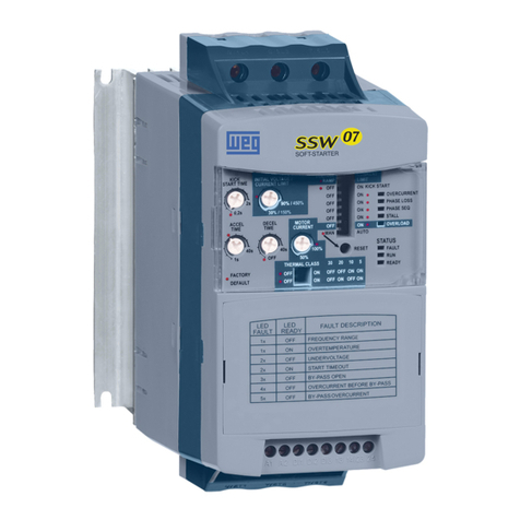
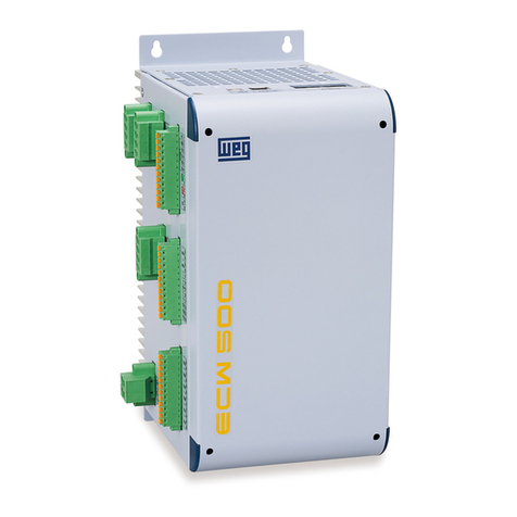
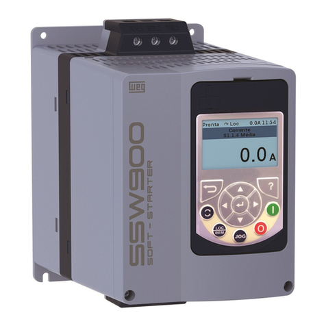
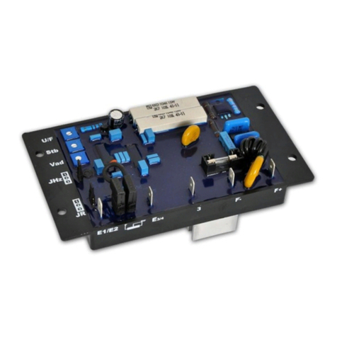
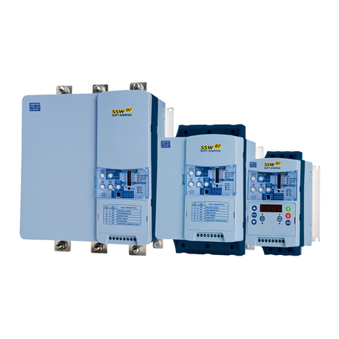
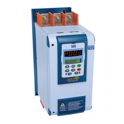
WEG SSW-05 Plus Series User manual

SOFT-STARTER
Arrancador Suave,
Chave de Partida Soft-Starter
Motors | Automation | Energy | Coatings
User’s Guide
Guia del Usuario
Manual do usuário

ENGLISH
SUMMARY - English
1. Safety Instructions .......................................................................................................................................03
2. What is the SSW-05 Plus Soft-Starter .........................................................................................................03
3. How to identify the SSW-05 Plus .................................................................................................................03
4.TechnicalData .............................................................................................................................................04
5. SSW-05 Plus Description ............................................................................................................................05
6.Table ofPowers/Currents/PowerWiring (copper wireat70°C(158oF)) ......................................................05
7.TableofConnectorTighteningTorque ...........................................................................................................05
8. Capacity of the Power Supply Line...............................................................................................................06
9. Table of Fuses and Contactors .....................................................................................................................06
10.Dimensions ................................................................................................................................................06
11. SSW-05 Plus Installation and Connection ..................................................................................................07
12. SSW-05 Plus Setting .................................................................................................................................08
13.Operation of the DigitalRelayOutputs........................................................................................................10
14. Protections and Displays ...........................................................................................................................11
15.OverloadProtection ....................................................................................................................................12
16.Reset .........................................................................................................................................................13
17. Faults and Possibles Causes.....................................................................................................................13
18.Solvingthemostfrequent problems ............................................................................................................15
19. SSW- Options andAccessories .................................................................................................................15
20.Table of Parameters (for serial communication/HMI-SSW05-RS) ................................................................20
21.Errorcode and description (for serialcommunication/HMI-SSW05-RS) ....................................................21
22.DetailedParameterDescription(forserialcommunication/HMI-SSW05-RS)...............................................21
23.AppendixforCE Conformance ....................................................................................................................28
24.EUDeclarationofConformity......................................................................................................................29
Warranty SSW-05 Plus....................................................................................................................................30
ENGLISH
Note: 1) The SSW-05 Plus electronic Soft-Starter has been designed to drive three-phase induction motors
applied to light duty loads, such as centrifugal pumps, small fans and screw compressors.
If the Soft-Starter shall be applied on heavy duty loads, please contact WEG.
2) The serial communication is available in the SSW-05 with software versions greater than V2.00.
The manual of the serial communication (0899.4587) is available for download on the website
www.weg.com.br.
With the serial communication is possible:
a) to connect the Soft-Starter in an equipment network, like PC, PLC, and others;
b) to use with SuperDrive software (417102505) for Microsoft Windows, allowing the SSW-05
programming and operation;
c) to use the remote HMI (human machine interface) for SSW-05 programming and operation.
1.SAFETYINSTRUCTIONS:
Always disconnect the power supply from the equipment before attempting any maintenance work.
Personnel must review this entire Manual before attempting to install and operate the SSW-05 Plus Soft-Starter.
Only qualified personnel should plan or implement the installation, start-up, setting, operation and maintenance of
thisequipment.
2. WHAT IS THE SSW-05 PLUS SOFT-STARTER:
TheSSW-05Plus Soft-Starter allows smooth start/stopofthree-phase induction motors.
3. HOW TO IDENTIFY THE SSW-05 PLUS:
SSW05
Soft-Starter
WEG Series 05
0003
Rated Output
Current:
0003 = 3A
0010 = 10A
0016 = 16A
0023 = 23A
0030 = 30A
0045 = 45A
0060 = 60A
0085 = 85A
T
Three-phase
Power Supply
2246
Power Supply
Voltage:
2246 =
220 to 460V
4657 =
460 to 575V
P
Manual
Language:
P= Portuguese
E= English
S= Spanish
P
SSW-05
Version:
P= Plus
Z
End of Code
Series: SSW-05 Plus
Software Version: 2.0X
0899.4668 /5
INSTALLATION
AND OPERATION
MANUAL
Example:Thecode SSW050010T2246PPZ means a 10ASSW-05Plus,three-phasepower supply in the range
from220to 460V,manualinPortuguese,PLUS version.

ENGLISH
Model
AC Input Power Control Voltage (A1 andA2)
Power supply
(R/1L1, S/3L2, T/5L3)
Settings
Pedestal Voltage
Acceleration Time
Deceleration Time
Motor Current
Diagnostics
StartDuty Maximum Number of Starts
per hour
Starting Cycle
Digital Inputs
(90...250Vac 6mA)
Relay
Outputs (1A250Vac)
Communication Temperature
Ambient Humidity
Altitude
Degree of Protection
Polution Degree (UL508)
Mounting Fastening
Enclosure
Electromagnetic Compatibility
(EMC)
Low Voltage
SSW-05 Plus
90 ... 250Vac 50/60 Hz (+/- 6Hz)
200 mA
220 ...460 Vac (+10%,-15%) 50/60 Hz (+/- 5Hz) 3φ
460 ... 575 Vac (+10%,-15%) 50/60 Hz (+/- 5Hz) 3φ
30 ... 80% UN
1 ... 20 s
Off ... 20 s
30 ... 100% IN
4 ( 1 start every 15 minutes)
3 x IN during 10 seconds
0 ... 55°C (32...131°F)
5 ... 90% Non Condensing
0 ... 1000m (up to 13,200 ft (4000m) with
10% output current derating/1000m)
IP 00 (Chassis)
2
DIN 35mm rail or M4 fastening bolts
Molded plastic box
Class A (industrial use)
IEC 60947-4-2 Standard
UL 508 / IEC 60947-4-2
4.TECHNICALDATA:
Standards
Motor Overload Protection
Incorrect Phase Sequence
Phase Loss
Immediate Overcurrent
Locked Rotor
Thyristor Overload
Immediate Overload at
By-pass Relay
Overcurrent before By-pass
Frequency out of Tolerance
Internal By-pass Relay
Contact is open
Undervoltage at control
voltage
DI1 – Enable/Disable Function
DI2 – Reset Function
Operation Function (13 – 14/23)
Full Voltage Function (14/23 – 24)
Serial Interface (RS232C)

ENGLISH
5. SSW-05 PLUS DESCRIPTION:
7.TABLEOFCONNECTOR TORQUESETTINGS:
SSW-05 Plus
Size
1
2
Torque-Power Terminals
(R, S, T, U, V and W)
Nm (lb-in)
3.0 (32.7)
5.5 (60.0)
Nm (lb-in)
0.5 (4.5)
0.5 (4.5)
Torque of
Electronics Terminal
* Accordingto able 45.2, UL508.
** Valid for Standard 4 pole WEG motors.
6. TABLE OF POWERS / CURRENTS / POWER WIRING (COPPER WIREAT 70°C (158OF)):
Model
SSW-05.3
SSW-05.10
SSW-05.16
SSW-05.23
SSW-05.30
SSW-05.45
SSW-05.60
SSW-05.85
Rated
Current
3A
10A
16A
23A
30A
45A
60A
85A
220V...240V*
HP kW
0.75 0.55
3 2.2
5 3.7
7.5 5.5
10 7.5
15 11
20 15
30 22
380V...415V*
HP kW
1.5 1.1
5 3.7
7.5 5.5
10 7.5
15 11
25 18.5
30 22
50 37
440V...480V*
HP kW
1.5 1.1
5 3.7
10 7.5
15 11
20 15
30 22
40 30
60 45
Power Wiring
mm2(AWG)
0.75 (18)
1.5 (16)
4 (12)
6 (10)
10 (8)
16 (6)
25 (4)
35 (2)
Size
1
2
525V**
kW
1.5
5.5
11
15
18.5
30
45
55
575V*
HP
2
7.5
10
20
25
40
50
75
Setting Trimpots
Reset Button
Dip-switch for Protection
Enable
Three-phase Input Power Supply
Reset (DI2)
MotorEnable/DisableCommand(DI1)
Electronics Power Supply (A1 and A2)
SSW-05 Plus Status LEDS
Relay Output (13, 14/23 and 24)
Output to motor
Connector for Serial
Interface or HMI

ENGLISH
8. CAPACITY OF THE POWER SUPPLYLINE:
The SSW-05 Plus is suitable to be used in circuits that can not supply more than XARMS (according to table below)
symmetric Ampères, Y Volts maximum:
SSW-05 Plus
Model
3A
10A
16A
23A
30A
45A
60A
85A
Y = 220- 575V
X (kA)
5
5
5
5
5
5
5
10
9. TABLE OF FUSESAND CONTACTORS (SEE ITEM 11):
SSW-05 Plus
Model
3A
10A
16A
23A
30A
45A
60A
85A
Contactor
(K1)
CWM09
CWM12
CWM18
CWM25
CWM32
CWM50
CWM65
CWM95
Fuse
(F1,F2,F3)
Type D 10A
Type D 16A
Type D 25A
Type D 35A
Type D 50A
Type D 63A
Type NH 100A
Type NH 125A
Fuse
(F11, F12,F21)
Type D6A
10.DIMENSIONS:
Notes:
1) The SSW-05 Plus can be fixed on DIN 35mm rail.
2) In the case of fixing through M4 screw, the torque should not be greater than 0.2 Nm (1.77 lb in) for the upper
screws and 1.0 Nm (8.85 lb in) for the lower screws.
Size
1
2
Width L
mm (in)
59 (2.32)
79 (3.11)
Depth P
mm (in)
145 (5.70)
172 (6.77)
FixingA
mm (in)
51 (2.00)
71 (2.79)
FixingB
mm (in)
122 (4.80)
177 (6.17)
Fixing
M4 screw/ Rail
M4 screw/ Rail
Weight
kg (Lb)
0.74 (1.63)
1.67 (3.68)
HeightH
mm (in)
130 (5.11)
185 (7.28)
FixingD
mm (in)
61 (2.40)
99 (3.89)

ENGLISH
11. SSW-05 PLUS INSTALLATION AND CONNECTION:
11.1. Simplified Start/Stop on 230V/400 line:
11.2.Starting andStoppingusing ContactorandPushButtons:
The “T1” transformer is only required when the
line voltage is out of the range allowed for the
electronics supply (90 – 250Vac). For 400V,
use neutral conductor (N) and one phase.
230/400V Symbol Description
Fuse
Disconnecting Switch
(opens under load)
Transformer
N.O. switch
(with holding)
N.C. push button
(with automatic return)
N.O. push button
(with automatic return)
Contactor (coil)
Three-phase induction
motor
Symbol Description
Fuse
Disconnecting Switch
(opens under load)
Transformer
N.O. switch
(with holding)
N.C. push button
(with automatic return)
N.O. push button
(with automatic return)
Contactor (coil)
Three-phase induction
motor

ENGLISH
11.3. Start/Stop by using Push Button and Operation Function Relay of the SSW-05 Plus:
The “T1” transformer is only required when the
line voltage is out of the range allowed for the
electronics supply (90 – 250Vac). For 400V,
use neutral conductor (N) and one phase.
12. SSW-05 PLUS SETTING:
12.1. Pedestal Voltage Setting:
Set the pedestal voltage to a value that the motor starts to run as soon as run command is given by the SSW-05
Plus.
12.2. Setting of the acceleration ramp time:
Set the value so that the motor accelerates to the rated speed.
Note: Please consider that in the cases where rated SSW-05 Plus current is equal to the rated motor current,
the SSW-05 Plus can be operated, at maximum, during 10 seconds at 3 x IN.
Trimpot for the
pedestal
voltage setting
Trimpot for
the
acceleration
Ramptime
setting
Symbol Description
Fuse
Disconnecting Switch
(opens under load)
Transformer
N.O. switch
(with holding)
N.C. push button
(with automatic return)
N.O. push button
(with automatic return)
Contactor (coil)
Three-phase induction
motor
The dot
indicates the
factory default

ENGLISH
12.3. Setting of the deceleration ramp:
Thissettingshouldbe used only for decelerationofpumpsinordertoreduce hydraulic shocks. This setting mustbe
madeinorder to obtain thebestpumpperformance.
12.4. Setting of the Motor Current:
Thissettingdefinestheratioof the SSW-05 Plus currentandthedrivenmotorcurrent.Thesettingofthis value is very
important, since it defines the protection of the motor driven by the SSW-05 Plus. The setting of this function has
directinfluenceoverthefollowingmotorprotections: overcurrent, overload, locked rotor,phaseloss.
Trimpot for the
deceleration
Ramptime
setting
Calculationexample:
Used SSW-05 Plus: 30A
UsedMotor: 25A
Setting of the Motor Current = IMotor
ISSW-05 Plus
Setting of the Motor Current =25A
30A
Setting of the Motor Current = 0.833
Thus it must be set at 83%.
Trimpot for
the motor
current
setting

ENGLISH
13. OPERATION OF THE DIGITALRELAYOUTPUTS:
The relay of the Operation Function closes its N.O. contact (13-14/23) always when the SSW-05 Plus receives the
enable command. This contact is open only at the end of the deceleration ramp (when it is set via trimpot) or when
the SSW-05 Plus receives the disable command.
The relay of the Full Voltage Function closes the N.O. contact (14/23-24) always when the SSW-05 Plus applies
100%voltageto the driven motor.Thiscontactopenswhen the SSW-05Plus receives thedisablecommand.
t
t
t
Relay On

ENGLISH
14.PROTECTIONSANDDISPLAYS:
Protection/Display Display
Description
LED
(overcurrent)
Overcurrent*
Phase Loss* LED
(Phase Loss)
Locked Rotor* LED (Stall)
Motor overload LED
protection* (Overload)
Overcurrent of the LED
SSW-05 Plus (Internal Fault)
By-pass relay
LED
Overcurrent before Internal Fault)
By-pass
Thyristor LED
overload (Internal Fault)
Frequency out LED
of Tolerance (Internal Fault)
Internal By-pass LED
relay contact is (Internal Fault)
open
Undervoltage in the LED
Control Supply (Internal Fault)
LED
Ready to operate (Ready)
In Operation LED
(Run)
Activation
Monitoring is activated only when the SSW-05 Plus is in rated duty
(100% voltage). It trips, when the motor current exceeds 3 times the
value set with the trimpot (Motor Current) during a time longer than 1
second.
It trips after 1s elapses with phase loss, both at the input and at the
output (Motor).
It trips when the current flowing through the SSW-05 is lower than
30% of the current set with trimpot (Motor Current).
The error trips when in incorrect phase sequence.
This protection trips during the transition between the end
of the acceleration ramp time and the contact closure of the internal
by-pass relays of the SSW-05 Plus, when the current flowing through
the SSW-05 Plus is higher than or equal to 2 times the current set
with trimpot (Motor Current).
This protection monitors constantly the motor current and compa-
res it with the value set by the trimpot (Motor Current).
See Item 15.
This protection monitors only when SSW-05 Plus is operating at full
voltage(100%).Ittripswhenthecurrentbecomeshigherthan 2
times the rated current of the SSW-05 Plus and is present for more
than 1 second. The internal fault LED flashes 5 times intermittently.
This protection trips during the transition between the end of the
acceleration ramp time and the contact making of the internal by-
pass relays of the SSW-05 Plus, when the current flowing through
the SSW-05 Plus is higher or equal to 2 times the rated current of the
SSW-05 Plus. The internal fault LED flashes 4 times intermittently.
This protection monitors the current that flows through the SSW-05
Plus during the acceleration and deceleration ramp time, and com-
pares it with the rated current of the SSW-05 Plus. Fig. 15.2 shows
the trip time curves when thyristors are overloaded. The internal fault
LED flashes 6 times intermittently.
This protection trips when the line frequency is out of range (+/-
10%), when compared with the rated frequency (50 Hz or 60Hz). The
internal fault LED flashes 1 time intermittently.
This protection monitors, if the contact of the internal by-pass relay
of the SSW-05 Plus is closed ( it operates only when the SSW-05
Plus is operated at full voltage (100%). The internal fault LED fla-
shes 3 times intermittently.
This protection monitors the control supply voltage of the electronics
(A1 and A2) constantly and trip always when Vac voltage become
lower than 80% of the rated voltage. The internal fault LED flashes 2
times intermittently.
- ON: SSW-05 Plus has been powered, and is waiting for the enable
command, or with full voltage at output. - Flashing: SSW-05 Plus in
acceleration/deceleration ramp time.
It is On only when SSW-05 Plus is operating (motor is operating with
full voltage).
*Theseprotectionsmay be enabled/disabled through the respectivedip-switches.
Incorrect Phase LED
Sequence* (Phase Seq)

ENGLISH
15.OVERLOADPROTECTION:
15.1. Motor Electronic Overload Protection:
Themotorelectronicoverload protection simulatesthemotorheating (ThermalImage).Thisheating simulationuses
as input data the True RMS current. Fig. 15.1 shows the curve of the actuation time with motor under overload
condition. The temperature class of this function is, according to the IEC 947-4-2, Class 10.
Figure15.1-Curveofthemotorelectronicoverloadprotection.
Notes:
1) When SSW-05 Plus electronics (A1 and A2) is without power control supply voltage, the thermal image
is saved internally. When the power supply voltage is re-established again (A1 and A2), the value of the
thermal image returns to the value present before the loss of the power control supply.
2) When the electronic overload protection is disabled via dip-switch, the thermal image is reset;
3) The reset of the electronic overload protection can be set to manual function (man). In this case the
reset must be made via digital input 2 (DI2) or by means of the reset button. If the reset setting has been
set to automatic (auto), the error condition will be reset automatically after the cooling of the equipment.
t(s)
1 + 104
1 + 103
100
10
1100 200 300 400 500 600 700 800% Ief
ColdCondition
HotCondition
Figure15.2-Curveof the thyristor overload.
t(s)
1 + 103
100
10
1
0.1100 200 300 400 500 600 700 800% In
ColdCondition
HotCondition
Note:
Whenthemotor is running in full voltage,thecoolingofthe thyristor overload Thermal Image happens.
This is because of the By-pass of the thyristors.

ENGLISH
16.RESET:
Theerror condition can beresetthrough the reset buttonatthe front of the SSW-05Plus,or through a momentary
contact closure (0.5 seconds) at DI2 (digital input for reset). Other alternative to reset the SSW-05 Plus is by
switching On/Off the power control supply of the electronics (A1 andA2).
Note:
TheSSW-05 Plus alsoprovides the automatic resetby enabling thisfunctionthrough the dip-switch(auto):
1) The automatic reset occurs after 15 minutes in the following fault conditions:
- Overcurrent,PhaseLoss,LockedRotor,Immediate overcurrent of theSSW-05Plus by-passrelay, Overcurrent
before By-pass, Frequency out of tolerance, Contact of the internal By-pass relay is open and power control
supplyundervoltage.
2) For incorrect phase sequence there is no automatic reset.
3) Formotor overload and thyristoroverloadthere is a specific algorithmforthe automatic reset time.
VERYIMPORTANT!
Bothdigitalinput (DI2) and reset button oftheSSW-05Plusshouldbe used only for theresetafterafaultcondition.
IftheresetfunctionisusedwhentheSSW-05Plusisoperatingatratedvoltage,theinternal by-pass relays will open
theircontacts under load,thusjeopardizing their life.
Protection
Description
Phase Loss
Motor Overload
External Fault
Error in the Copy
Function
SSW-05
Front Panel
LED
(Phase Loss)
LED
(Overload)
Available only when
HMI-SSW05-RS or serial
communication is used
(see chapter 19)
Available only when
HMI-SSW05-RS is used
(see chapter 19)
HMI-SSW05-RS
(see chapter 19.3)
E03
E05
E06
E10
17. FAULTS AND POSSIBLE CAUSES:
When a fault is detected, the Soft-Starter is disabled and the Fault Code is displayed by flashing LED´s or on the
readoutdisplayinthe EXX form, whereXX isthe actual FaultCode.
TorestarttheSoft-Starterafterafaulthasoccurred,theSoft-Startermustbereset.Ingeneral,theresetcanbemade
asfollows:
disconnectingandreapplyingtheACpower (power-on reset);
by pressing the key “RESET” on the SSW05-RS front panel (reset key);
through the HMI-SSW05-RS by pressing the key (manual reset);
automaticreset by enabling thefunctionthroughthe dip-switch (auto) or though P106andP220.
viadigitalinput:DI2.
Table below explains how to reset the fault and show the possible causes for each Fault Code.
Possibles Causes
Phase fault in the three-phase
network
Short-circuit or thyristor fault
Motor is not connected
Motor connection is not correct
“Motor Current” trimpot or P105
(motor current) has been set
incorrectly. The set value is too
low for the motor being used.
Load on the motor shaft too high.
Too much successive motor starts.
The wiring at DI1 is open (not
connected).
Keypad cable misconnected.
Electrical noise in the
installation (electromagnetic
interference).
Fault Display Reset
Power-on
Reset key
key
Auto-reset
DI2.
Power-on
key
Auto-reset
Power-on
Reset key
key
DI2.
Power-on
key

ENGLISH
Protection
Description
KeypadHMI
Connection Fault
Locked Rotor
Thyristor overload
Overcurrent
Incorrect phase
sequence
Undervoltage in the
Control Supply
Internal
By-pass relay
contact is open
Overcurrent before
By-pass
Overcurrent of the
SSW-05 By-pass
relay
Frequency out of
tolerance
SSW-05
Front Panel
Available only when
HMI-SSW05-RS is used
(see chapter 19)
LED
(Stall)
LED
(Internal Fault)
flashes 6 times
LED
(Overcurrent)
LED
(Phase Seq)
LED
(Internal Fault)
flashes 2 times
LED
(Internal Fault)
flashes 3 times
LED
(Internal Fault)
flashes 4 times
LED
(Internal Fault)
flashes 5 times
LED
(Internal Fault)
flashes 1 time
HMI-SSW05-RS
(see chapter 19.3)
E31
E63
E64
E66
E67
E70
E71
E72
E73
E75
Reset
Power-on
This fault disa-
ppears automa-
tically when HMI
reestablishes
the communi-
cation with the
Soft-Starter.
Power-on
Reset key
key
Auto-reset
DI2.
key
Auto-reset
Power-on
Reset key
key
Auto-reset
DI2.
Power-on
Reset key
key
DI2.
Power-on
Reset key
key
Auto-reset
DI2.
Power-on
Reset key
key
Auto-reset
DI2.
Power-on
Reset key
key
Auto-reset
DI2.
Power-on
Reset key
key
Auto-reset
DI2.
Power-on
Reset key
key
Auto-reset
DI2.
Possibles Causes
Keypad cable misconnected.
Electrical noise in the
installation (electromagnetic
interference).
The time programmed for the
acceleration ramp is shorter than
the actual acceleration time.
Load on the motor shaft too high
Too much successive starts.
Short-circuit between phases.
Motor shaft is locked.
Network phase sequence
inverted at the input.
Electronicssupplylower thanthe
required one.
SSW-05 is defective.
The time programmed for the
acceleration ramp is shorter than
the actual acceleration time.
Short-circuit between phases.
Motor shaft is locked.
The line frequency is out of ran-
ge (+/- 10%), when compared
with the rated frequency (50Hz
or 60Hz).
Fault Display
Note:
To prevent the E31fault,whenHMI-SSW05-RSisapplied, please avoid resetting thefaultthroughthedigitalinputs
(DI2)and through theresetkey located ontheSSW-05 front panel.

ENGLISH
18.SOLVINGTHEMOSTFREQUENTPROBLEMS:
Problem
Motor does not
runs
Motor speed
oscillates
Motor speed
too high or too low
Shocks during pump
deceleration
Shocks during pump
acceleration
Points to be checked
Wrong wiring
Power Supply Loss
Setting
Fault
Loose connections
Motor Nameplate Data
Soft-Starter Setting
Corrective Actions
1. Check all power and control connections
1. Check the power supply (R, S, T)
2. Check the power control supply (A1, A2)
1. Check if the settings are correct for the application.
1. Check if the SSW-05 Plus is not in locking condition
(refer to item 14 – Protections and Display).
1. Switch Off the SSW-05 Plus, switch off the power supply and
tighten all connections.
2. Check all internal SSW-05 Plus connections.
1. Check if the motor has been selected according to the application.
1. Reduce the time of the deceleration ramp time.
1. Reduce the time of the acceleration ramp time.
2. Reduce the setting of the pedestal voltage.
19. SSW-05 OPTIONS AND ACCESSORIES:
This chapter describes the optional devices that can be used with the SSW-05. The table below shows a list of
existingoptionaldevices.
Name
CAB-RS-1
CAB-RS-2
CAB-RS-3
MIW-02
HMI-SSW05-RS
Function
Cable for the remote serial keypad - cable: 1m (3.28ft)
Cable for the remote serial keypad - cable: 2m (6.56ft)
Cable for the remote serial keypad - cable: 3m (9.84ft)
RS-232 to RS-485 conversion module
External serial Keypad HMI. For remote use with the
CAB-RScable(up to 3m(9.84ft)). Keypad CopyFunction.
WEG Item
Number
0307.7827
0307.7828
0307.7829
417100543
417100996
19.1.CAB-RS-1,CAB-RS-2, CAB-RS-3:
Cablesused to connect theSoft-Starterto the external serialinterfacekeypad(HMI-SSW05-RS).
There are 3 cables options ranging in lenghts from 1m (3.28ft) to 3m (9.84ft). The user must select among these
lengthsaccordingto his requirement.
You must plan carefully the wiring location by separating it at least 10cm (3.9in) from the power wiring.
Table19.1-AvailableoptionaldevicesfortheSSW-05.
Soft-Starter
RJ Connector
HMI
DB9 Connector
DB9 PINS
1 Vcc
2RX
3TX
5 GND
CABLE CONECTIONS
RJ PINS
1 Vcc
6TX
4RX
5 GND
Figure19.1-CableCAB-RSforHMI-SSW05-RS.

ENGLISH
19.2. MIW-02:
Externalmoduleforconversion from RS-232toRS-485:itallowstheconnection of theSSW-05toastandardRS-485
line. So the Soft-Starter can participate in a multipoint line up to 1000m (3280ft) without the use of transducers.
Formoredetailsaboutthisconnection,seetheMIW-02USERMANUAL(0899.4430),availablefordownloadonthe
websitewww.weg.com.br.
Figure19.2 - Connection of theSSW-05to a standard RS-485communicationnetwork.
Weg Network RS-485
MIW-02
SSW-05 RJ Connector
Serial Port RS-232
RS-485
RS-232
19.3. HMI-SSW05-RS:
Remoteserial keypad:this interface is mounted externaltothe Soft-Starterandcanbe used in thefollowingcases:
applicationsthat require a remote keypad;
installationonpanel door;
whenthekeypadcopyfunctionis required for the transferofparametervalues from oneSoft-Startertoanother.
It operates with the cable CAB-RS-X, which length must be chosen according to the needs (up to 9.84ft).
Figure19.3- Dimensions of the HMI-SSW05-RS.

ENGLISH
Figure19.4-Frontview of the HMI-SSW05-RS.
Functions of the LED Display:
The LED display shows the parameter number and its value. It also shows the fault codes and status.
Functions of the “ready” and “run” LEDs:
Ready- On: SSW-05 Plus has been powered, and is waiting for the enable command, or with full voltage at output.
- Flashing: SSW-05 in acceleration or deceleration ramp time.
Run - It is On only when SSW-05 is operating (motor is operating with full voltage).
Led “Run”
Led “Ready”
LEDDisplay
19.3.3. Signaling/Indications on the HMI-SSW05-RS Display:
Soft-StarterStatus:
Soft-Starter is ready to be started.
Basic Functions of the Keys:
-Enablethe Soft-Starter (Start);
- Disable the Soft-Starter (Stop).Also resets the Soft-Starter after a fault has occurred;
-TogglestheLEDdisplaybetweenparameternumber and itsvalue(number/value);
-Increasestheparameternumberortheparametervalue.
-Decreasestheparameternumberortheparametervalue.
Note:
Intheoccurrenceoferrorswhenusing an HMI-SSW05-RS, the reset of errors must be done throughthekey .
Resetthroughthekeypresentin the frontalof the Soft-StartercauseslossofcommunicationoftheHMI, resulting in
E31. To re-establish the communication between the HMI and the Soft-Starter it is necessary to detach and to
reconnectthe serial cable,or else topower down and topower up theSoft-Starter again.
19.3.2. Use of the keypad:
Thekeypadis used for programming and operatingtheSSW-05,allowingthefollowing functions:
-indicationof the Soft-Starterstatus and operation variables;
- fault indication and diagnostics;
-viewingandprogramming parameters;
- operation of the Soft-Starter (Keys and ).
19.3.1. HMI-SSW05-RS Description:
The HMI-SSW05-RS has a LED display with 4 digits of 7 segments, 2 status LEDs and 5 keys. The figure below
showsthefront view of thekeypad.

ENGLISH
Soft-Starter is in fault condition.The code is flashing. In our example, the fault message is E03
(PhaseLoss).
Soft-Starter is executing thefunction“Loadfactory setting (P204)”
Note:
The display also flashes, besides the fault condition, in the following condition:
Attempt to change parameter with incorrect password (P000 –Access Parameter);
Attemptto change not permittedparameter. Example: Parametersthatcannot be changed withrunningmotor.
19.3.4. Parameter Viewing and Programming:
All SSW-05 settings can be made through parameters. The parameter are shown on the display by the letter P
followedbyanumber:
Example(P264):
Each parameter is associated with a numerical value (parameter value), that corresponds to the selected option
amongtheavailableonesforthisparameter.
TheparametervaluesdefinetheSoft-Starterprogramming or the valueofavariable(e.g.:current,voltage).ForSoft-
Starterprogrammingyoushouldchangetheparametercontent(s).
264=parameternumber
ACTION HMIDISPLAY DESCRIPTION
Turn ON the Soft-Starter
Press the key
Use the keys and
to reach P264
Press the Key
Use the keys and
Press the Key
Soft-Starter is ready to be operated
Select the desired parameter
Numerical value associated with the
parameter (2)
Set the new desired value (2)
(1)(2)
Note:
(1) By pressing the key after the reprogramming, the new programmed value will be stored automatically
andwillremain stored until a newvalueisprogrammed.
(2)To allow the reprogramming ofanyparameter(exceptforP000)it is required to setP000=5.Otherwiseyou can
onlyread the parameter values, butnotreprogram them. For more details,seeP000detailed description.

ENGLISH
19.3.5. HMI-SSW05-RS Installation:
The HMI-SSW05-RS can be installed directly on the panel door 1 to 3mm (0.04in to 0.12in), as shown in the figure
below:
Figure19.5-HMI-SSW05-RSInstallation.
19.3.6. HMI-SSW05-RS Start-up:
Afterinstallation(includinginterconnectingcable),power up the Soft-Starter.
TheHMI-SSW05-RSmustdisplay “rdy”.
To enable the keys and of the HMI-SSW05-RS, is necessary to program P264 ≠1.
19.3.7. Keypad Copy Function:
TheHMI-SSW05-RSkeypadstillhasanadditionalfunction:theKeypadCopyFunction.Thisfunctionisusefulwhen
onewantstocopythesettingsof one Soft-Starter (source Soft-Starter) to another (targetSoft-Starter)oroneneeds
toprogram several Soft-Starterswith the same settings.
This is done as follows: the parameters of the source Soft-Starter are copied to a non-volatile memory of the HMI-
SSW05-RS Keypad, and then from this keypad to another Soft-Starter (“target Soft-Starter”). The keypad copy
functionis controlled by theparameterP215.
Forfurtherinformationon this function, refer to detailedparameterdescriptionofP215.

ENGLISH
P101 Initial voltage 30 ... 80 (% Un) 30 21
P102 Time of the Acceleration Ramp 1 ... 20 (s) 10 22
P104 Time of the Deceleration Ramp 0 ... 20 (s) 0 = off 22
P105(1) Motor Current Setting 30 ... 100 (%) 100 22
P106(1) Protection Configuration 0 ... 3F Hexadecimal 1FHex. 22
P204(1) Load Factory Setting
0 = No function
025
1 = No function
2 = No function
3 = No function
4 = No function
5 = Load factory default
P215 (1) Keypad Copy Function 0 = Off 025
1 = Copy (SSW -> keypad)
2 = Paste (keypad -> SSW)
P220 (1) HMI/(Trimpots and Dip Switch) 0 = Trimpots and Dip Switch 026
Selection 1= HMI
P264 (1) Programmable Digital Input 0 = Not used 126
DI 1 1 = Enable / Disable
2 = External Fault
P277 (1) Programmable relay output 1 = Full voltage 126
(14/23 - 24) 2 = Error
3 = Serial Com.
P295(1) (2) Rated current of the Soft-Starter
0 = 3A
26
1 = 10A
2 = 16A
3 = 23A
4 = 30A
5 = 45A
6 = 60A
7 = 85A
P308 Network Address 1 ... 30 1 26
P313 Action of the serial 1 = only Error
26
communication verification 2 = ramp disabling
3 = General disabling
4 = P264 → 1
P314 Verification Time of the 0 ... 5 (s) 0 = oFF 27
Serial Communication
Parameter Parameter Function Range of the Factory User Page
(Reading and Writing) Internal Values Setting Setting
20.TABLE OF PARAMETERS (FOR SERIALCOMMUNICATION / HMI-SSW05-RS):
P000 (2) Parameter Access 0 ... 4, 6... 9999 = Read 021
5 =Alteration
P002 Motor Current Indication (%) 000,0 ... 999,9 (% In) 21
P003 Motor Current Indication (A) 000,0 ... 999,9 (A) 21
P023 Software Version 21
P050 Status Indication of the 0 ... 250 21
motor overload protection 250 = error
Parameter Parameter Function Range of the Factory User Page
(Reading) Internal Values Setting Setting
According
to the Type
(1) These Parameters can be changed only with stopped motor.
(2) These Parameters are not changed through the function “Loads Parameters with Factory Setting” (P204).
This manual suits for next models
8
Table of contents
Languages:
Other WEG Controllers manuals

WEG
WEG AVR-A-OPT-04E Installation and operating instructions

WEG
WEG SSW-08 Owner's manual

WEG
WEG SSW900-CAN-W User manual

WEG
WEG PDWCA User manual

WEG
WEG SSW07 Series User manual

WEG
WEG RUW-01 User manual

WEG
WEG AVR-A-OPT-06 User manual

WEG
WEG GRT7-TR1 User manual

WEG
WEG PDWD User manual

WEG
WEG GRT7-TH4E User manual
Popular Controllers manuals by other brands

HID
HID Mercury LP4502 Installations and specifications

Vacon
Vacon NX ACTIVE FRONT END II Applications manual

CSS MicroSystems
CSS MicroSystems AssistX Mobil SNELGIDS quick start

Samson
Samson 3273 Mounting and operating instructions

HighPoint
HighPoint RocketRAID 3G mini SAS HBA Series installation guide

Gardena
Gardena 1273 operating instructions