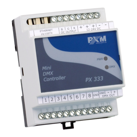
PXM Wireless DMX User manual

MANUAL
DMX
Controller
R
PX710

TABLE OF CONTENTS
1. General description...................................................................................
2. Safety conditions.......................................................................................
3. Device design and description of connectors............................................
4. Connection method...................................................................................
5. Network settings for the driver...................................................................
5.1 Changing the network configuration of the computer.............................
6. Installing software......................................................................................
®
6.1. Windows platform................................................................................
®
6.2. Mac OS X platform..............................................................................
6.3. Android™ platform................................................................................
7. Logging......................................................................................................
8. Controller configuration.............................................................................
9. Controller operation...................................................................................
9.1 Calculation of output values...................................................................
9.2 Modbus..................................................................................................
9.3 Live mode...............................................................................................
9.4 Indication lights......................................................................................
9.5 RESET button operation, restoring default settings...............................
9.6 Core mode, FTP support........................................................................
10. Technical specifications...........................................................................
11. Technical drawing....................................................................................
Declaration of conformity...............................................................................
The manufacturer reserves the right to change the operation and handling of the
controller in order to improve the product.
2
tel.: (12) 385 83 06
fax: (12) 626 46 94
E-mail: [email protected]
Internet: www.pxm.pl
ver. 1.1
PXM Marek Żupnik spółka komandytowa
Podłęże 654
32-003 Podłęże
3
3
4
6
11
17
19
19
19
20
20
21
28
28
29
36
37
38
39
40
41
42

1. GENERAL DESCRIPTION
2. SAFETY CONDITIONS
Controller PX710 DMX Controller s a device powered with safe voltage 12-24 V; however, during
its installation and use the following rules must be strictly observed:
1. The device can be connected to 12-24 V DC (stabilised voltage) with current-carrying capacity
compatible with technical data.
2. All the conductors should be protected against mechanical and thermal damage.
3. In case of damage to a conductor, it should be replaced with a conductor of the same technical
parameters.
4. Connection of DMX signal can be made with a shielded conductor only.
5. All repairs, connecting and disconnecting of cables can only be made with cut off power supply.
6. The device should be strictly protected against contact with water and other liquids.
7. All sudden shocks, particularly dropping, should be avoided.
8. The device cannot be turned on in places with humidity exceeding 90%.
9. The device cannot be used in places with temperature lower than +2°C or higher than +40°C.
10. Clean with damp cloth only.
The PX710 DMX Controller is an advanced architectural lighting controller that allows for
controlling even the most complex lighting systems.
With programmable functions, the device enables the control of lighting, multimedia, and other
devices that are operated based on the DMX protocol. After the configuration, the controller
operates independently.
The controller has 2 DMX output lines (1024 channels) and it allows for triggering multiple
configuration items at the same time. Events can be triggered by an astronomical clock, a real
time clock, programmed timers, analogue or digital inputs, mobile device applications or via the
Modbus protocol. It is possible to include additional expansion modules (up to 16 lines).
® ®
An advanced PC application (Windows , Mac ) allows for programming the device. The
application has a built-in library of devices that can be distributed on a graphic project, which
facilitates the creation of complex light shows, including ones that are synchronized with sound.
The controller comes with an application for mobile devices (Android™) which enables simple
control.
The controller can be used to create up to 16 users with different access rights. There is an option
to remotely log on to the controller from the external network.
3

4
3. DEVICE DESIGN AND DESCRIPTION OF CONNECTORS
Designations:
1. Power supply
2. DMX output (512 channels)
3. DMX input (512 channels)
4. KBD - for future applications
5. EXT - connection to an external touch panel
6. Synchronization - for future use
7. CAN bus
8. 10V + additional power supply for analogue inputs
9. 2 analogue outputs (0-10 V)
10. 4 analogue inputs (0-10 V)
11. 16 ON/OFF inputs
12. Sink/Source pin
13. Ethernet connector
14. Reset
15. 4 indicator lights
REM
10V 0-10V OUT
21 1
234
0-10V IN
11 2 346 7 8
510 11 12
914 15 1613 SS
1
RX+ RX- TX+ TX-
KBD
VCK+
3.2. 4.
10. 11.
9. 12.
1.
8.
13.
14.
15.
5.
SYNC
6.
2
H L
7.
CAN
MAIN CONTROLLER PX710M

Designations:
1. Power supply
2. DMX output (512 channels)
3. DMX input (512 channels)
4. Synchronization - for future use
5. CAN bus
6. Ethernet connector
7. Reset
8. 4 indicator lights
1
2.
1.
6.
7.
8.
3.
SYNC
4.
EXTENSION MODULE PX710S
2
H L
5.
CAN
5

4. CONNECTION METHOD
power supply
12-24 V DC
efekts
e.g. PxArt lamps controller
e.g. PX333
a) power connection for DMX output and DMX input
6
V-
V+ L N
REM
10V 0-10V OUT
21 1
234
0-10V IN
11 2 346 7 8
510 11 12
914 15 1613 SS
1
RX+ RX- TX+ TX-
KBD
VCK+
SYNC
2
H L
CAN
efekts
e.g. PxArt lamps

REM
10V 0-10V OUT
21 1
234
0-10V IN
11 2 346 7 8
510 11 12
914 15 1613 SS
1
RX+ RX- TX+ TX-
KBD
VCK+
SYNC
2
H L
CAN
b) Connection between a master controller (MASTER) and expansion modules (SLAVE)
1SYNC
2
H L
CAN
1SYNC
2
H L
CAN
maximum 7
expansion
modules
(SLAVES)
NOTE: It is necessary to connect a 120 Ω terminating resistor to the first and last device.
120 Ω
120 Ω
7

c) connection of analogue inputs (this applies only to PX710M)
REMOTE
10V 0-10V OUT
21 1
234
0-10V IN
11 2
GND
0 - 10V IN
0 - 10V IN
0 - 10V IN
0 - 10V IN
SOURCES SIGNAL 0 - 10V
REMOTE
10V 0-10V OUT
21 1
234
0-10V IN
11 2
POTENTIOMETERS
+10V OUT
GND
0 - 10V IN
0 - 10V IN
0 - 10V IN
0 - 10V IN
8

d) connection of digital inputs (this applies only to PX710M)
ŸSink in type - positive logic input - "joint plus"
S/S 1 2 34
R1 R1 R1 R1
R2 R2 R2 R2
X1 X2 X3 X4
12 - 24 V DC
+_
Power Supply
e.g.
input
buttons
controller
connectors
9

S/S 1 2 34
R1 R1 R1 R1
R2 R2 R2 R2
X1 X2 X3 X4
12 - 24V DC
+_
Power Supply
e.g.
input
circui
ŸSource in type - negative logic input - "joint mass"
10
controller
connectors

5. NETWORK SETTINGS OF THE CONTROLLER
The controller stores the static network configuration. It is always used when static addressing
mode was selected or in automatic addressing mode, when it was not possible to get the
configuration settings from the DHCP server.
The controller can run in one of the two modes:
• Automatic addressing: DHCP þ
• Static addressing: DHCP ¨
In automatic mode (DHCP), after connecting to the network, the controller attempts to get the
network configuration from a DHCP server (e.g. router). Thanks to this, manual configuration of
network parameters is not needed. In the absence of a DHCP server on the network, the
controller will operate according to the static configuration (manual setup).
When choosing static addressing, you should configure network parameters in such a way that
the controller is able to operate on the subnet and there is no conflict of IP addresses (devices in
the network must have unique IP addresses).
The default network settings of the controller:
DHCP: Included þ
IP: 192.168.0.50
Mask: 255.255.255.0
Gate: 192.168.0.1
Should the controller operate in automatic mode in the network and receive IP address from the
DHCP server, the detaching of the network cable will result in the loss of IP address and another
attempt to get the new IP address from the DHCP server. If that fails, the controller switches to
operate with a static configuration.
It is recommended to use automatic addressing and connect the controller to the network with a
running DHCP server.
Should the controller be connected directly to the computer (no DHCP server), you must
manually set the network parameters of both the computer and the controller to operate in one
network.
11

REM
10V 0-10V OUT
21 1
234
0-10V IN
11 2 346 7 8
510 11 12
914 15 1613 SS
1
RX+ RX- TX+ TX-
KBD
VCK+
SYNC
2
H L
CAN
REM
10V 0-10V OUT
21 1
234
0-10V IN
11 2 346 7 8
510 11 12
914 15 1613 SS
1
RX+ RX- TX+ TX-
KBD
VCK+
SYNC
2
H L
CAN
b) Connecting controller directly to the computer (no DHCP server)
PX710:
IP, mask and gate - optional
DHCP þ
PC:
„Obtain an IP address
automatically”
Below are some typical examples of network configuration:
a) Automatic addressing
Router:
np.:
IP: 192.168.0.100
Mask: 255.255.255.0
DHCP server þ
PC:
np.:
IP: 192.168.0.1
Mask: 255.255.255.0
PX710:
np.:
IP: 192.168.0.50
Mask: 255.255.255.0
DHCP (recommend)¨
When connecting the controller directly to a computer it is recommended to use a braided cable.
Newer network cards will work both on a braided cable or a non-braided cable, but older ones
may require a braided cable.
12
Smartphone:
smartphone receives
configuration on its own

REM
10V 0-10V OUT
21 1
234
0-10V IN
11 2 346 7 8
510 11 12
914 15 1613 SS
1
RX+ RX- TX+ TX-
KBD
VCK+
SYNC
2
H L
CAN
Router:
IP: 192.168.0.100
Mask: 255.255.255.0
DHCP server ¨
c) Static addressing
Smartphone:
IP: 192.168.0.2
Mask: 255.255.255.0
Default gateway: 192.168.0.100
PX710:
IP: 192.168.0.50
Mask: 255.255.255.0
Gate: 192.168.0.100
DHCP ¨
PC:
IP: 192.168.0.1
Mask: 255.255.255.0
Gate: 192.168.0.100
13

d) External connection
To connect via the Internet:
-Have an external IP address on the router assigned by your ISP, and have the possibility to
connect externally (incoming packets are not blocked by the ISP’s firewall),
-Forward any two ports (must be one after the other) to the IP address of the controller working
in the internal network, and to ports 50000 and 50001 UDP/TCP (port forwarding)
-Unblock the selected ports on the router firewall
-The address of the controller/controllers on the internal network cannot change (the
controller must have the address set statically or the DHCP server in the network must assign
the same IP address to the same devices every time).
Most routers on the market usually have several parameters in the port forwarding options.
These are:
ŸName of forwarding (any)
ŸForwarding port (or range of ports)
ŸProtocol type (TCP/UDP or both)
ŸLocal IP address (to which you want to forward)
FOR EXAMPLE:
1. One device/controller operates on the internal network
Assumptions:
ŸName of forwarding: it can be arbitrary but different for any forwarding
ŸExternal IP address: 188.188.188.188 (here, for example, replace it with the address
received from the ISP)
ŸForwarded ports (from the Internet): 50000 and 50001
ŸIP address on the local network (controller address): 192.168.0.50
ŸDestination ports (for the controller): 50000 and 50001
ŸProtocol: TCP/UDP (sometimes you can find the following options: “Both”, “All”, etc.)
The port with the lower address must be forwarded to the lower destination address of the
controller, and the port with the higher address - to the higher destination address of the
controller. If the port range setting option is not available, you need to create two forwarding rules
for each port individually (for 50000 and 50001).
Then, to connect to the controller via the Internet, in the application window "Connect to device" in
the "Address" field enter the IP address of the router (assigned by your ISP), which in this case is
188.188.188.188, and in the "port” field enter the lower of the forwarded ports, in this case port
50000.
See: figure on the next page.
14

REM
10V 0-10V OUT
21 1
234
0-10V IN
11 2 346 7 8
510 11 12
914 15 1613 SS
1
RX+ RX- TX+ TX-
KBD
VCK+
SYNC
2
H L
CAN
Router:
IP: 192.168.0.100
Mask: 255.255.255.0
DHCP server ¨
Port forwarding
PX710:
IP: 192.168.0.50
Mask: 255.255.255.0
Gate: 192.168.0.100
DHCP ¨
Internet connection
external IP address
Internet connection
2. Two or more devices/controllers working in the internal network
Assumptions:
ŸExternal IP address: 188.188.188.188 (here, for example, replace it with the address
received from the ISP)
ŸIP address of the first controller: 192.168.0.50
ŸIP address of the second controller: 192.168.0.51
ŸForwarded ports: 50000 and 50001 for the first controller, and 60000 and 60001 for the
second controller
ŸDestination ports (for the first forwarding and the second forwarding): 50000 and
50001
ŸProtocol: TCP/UDP (sometimes you can find the following options: “Both”, “All”, etc.)
If the port range setting option is not available you need to create two forwarding rules for each
port individually (for 50000 and 50001, and also 60000 and 60001).
15
INTERNET

REM
10V 0-10V OUT
21 1
234
0-10V IN
11 2 346 7 8
510 11 12
914 15 1613 SS
1
RX+ RX- TX+ TX-
KBD
VCK+
SYNC
2
H L
CAN
REM
10V 0-10V OUT
21 1
234
0-10V IN
11 2 346 7 8
510 11 12
914 15 1613 SS
1
RX+ RX- TX+ TX-
KBD
VCK+
SYNC
2
H L
CAN
Router:
IP: 192.168.0.100
Mask: 255.255.255.0
DHCP server ¨
Port forwarding
PX710:
IP: 192.168.0.50
Mask: 255.255.255.0
Gate: 192.168.0.100
DHCP ¨
external IP address
for example:
188.188.188.188: 50000
188.188.188.188: 60000
PX710:
IP: 192.168.0.51
Mask: 255.255.255.0
Gate: 192.168.0.100
DHCP ¨
188.188.188.188: 50000
188.188.188.188: 60000
Then, to connect to the controller via the Internet, in the application window "Connect to device" in
the "Address" field enter the IP address of the router (assigned by your ISP), which in this case is
188.188.188.188, and in the "port” field enter the lower of the forwarded ports for the first
controller, in this case port 50000. To connect to the second controller, change the port to the
lower one of the ports forwarded to the second controller (in the example: 60000).
NOTE: In both cases, it is essential to follow the principle that you should forward two ports side
by side, and the lower of the forwarded ports must be forwarded to the IP address of the
device in the internal network and port 50000, and the higher of the forwarded ports must
be forwarded to the IP address of your device in the internal network and port 50001.
16
Internet connection
Internet connection
INTERNET

The procedure for changing the computer network configuration varies depending on the
®
operating system. Windows 7 system is an example here.
17
5.1. Change of the computer network configuration
Change of the computer network configuration in the
®
Windows operating system is done in the following
way:
1. Click Start menu
2. Select [Control Panel] tab
3. Go to [Network and Internet] tab
4. Enter [Network and Sharing Center]
5. In the left panel, select the [Change adapter
settings]
6. Right-click on [Local area connection]
7. Select [Properties] from the context menu
8. Double-click [Internet Protocol Version 4
(TCP/IPv4)]
9. Select [Use the Following IP address:]
To connect directly (computer-controller) with a new controller (with preloaded default
configuration), use the sample settings:
IP address: 192.168.0.1
Subnet mask: 255.255.255.0
Default gareway: 192.168.0.100

18
Change of the computer network configuration in Mac OS X operating system is done in the
®
following way:
1. Click Start menu
2. Select the tab [System Preferences...]
3. Go to the tab [Network]
4. Highlight [Ethernet]
5. Configure IPv4: [Using DHCP]
6. Click [Apply]
Example settings:
IP address: 192.168.0.1
Subnet mask: 255.255.255.0
Default gareway: 192.168.0.100

19
6. INSTALLING SOFTWARE
The software can be installed on . The procedure for installing the
® ®
Windows 7 or Windows 8
software varies depending on the operating system on the computer. Windows 7 system is an
®
example here.
Installation is as follows:
1. Open an installation file, click [Next] to go to the software installation.
The installation file is attached to the driver on a CD, or available for download from the
http://pxm.pl
2. Select the folder in which the software is to be installed. Confirm your selection by clicking the
[Next] button.
3. Select components that you want to install, and then click [Next].
4. Read the license agreement carefully; if you agree to the terms of this agreement, click [Next]
to continue the installation.
5. Select the start menu in which you want to create a shortcut to the program. You can also
rename the directory, then click [Next].
6. The installer will ask again whether you want to install the software, click [Install] if you agree.
7. When the window indicating that the installation procedure was successful pops up, click
[Finish] to exit the installation wizard. If you want to go to the program, in the selection window
select [Run PXDesigner now].
®
8. Windows displays a security alert of the system, and to be able to use the PXDesigner
software, you need to allow access.
6.1. Windows platform
®
®
The application can be installed on Mac OS X , version 10.8 or later.
®
Software installation is similar as in the case of Windows platform.
6.2. Mac OS X platform
®

The application can be installed on Android 4.0 or later.
To install software:
1. Upload *.apk installation file available on the CD supplied with the device or downloaded from
the PXM website to your phone, or download an app from the Play Store using QR code:
6.3. Android™ platform
2. Go to your phone settings and then check “Allow installation of apps from sources other than
the Play Store ” in the [Security] tab.
3. Open the application through the system [File Manager].
The screen for the installed new software pops up. This screen displays information on the phone
functions that the application will use.
4. To install the application, press the "Install” button.
After a successful installation process, the application will be available in the application menu of
the phone.
20
7. LOGGING
Logging to the driver is possible to one of the users’ accounts created in the currently downloaded
configuration. The ADMIN account is always available.
Logging of a lot of users to the same account simultaneously is permissible to the account of the
ordinary user.
Only one person can log to the ADMIN account at the same time. If somebody has already logged
to the administrator’s account, it is possible to log them out using the option “force login.”
To log to the driver for the first time, write:
user: ADMIN
password: [the serial number of the device ]
The serial number has eight digits and is displayed next to the name of the
driver on the list of the found devices.
This is a default password for the ADMIN account which can be changed. After
restoring the default settings of the driver, the default password will also be
restored.
Other manuals for Wireless DMX
3
This manual suits for next models
2
Table of contents
Other PXM Controllers manuals