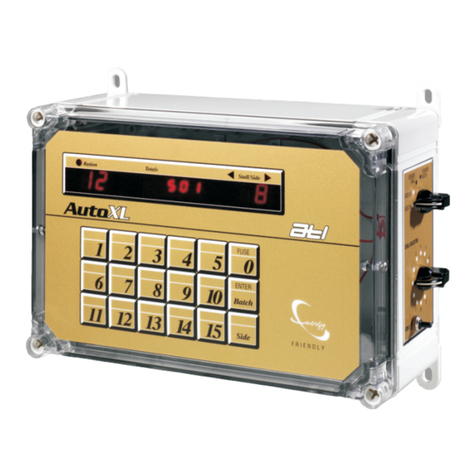
DIGITAL CONTROL
INSTALLATION
& OPERATION: 2
Installation
Power Supplies or Interfaces must be provided with a clean 230volt mains supply. Avoid
sharinganoutlet withanotherload.Use a switched,fusedoutletnota13Ampplugandsocket.
Position the Digital Feeder Controls as high as possible away from moisture and splashes
butwithineasy, convenient reach.Cableruns shouldbeas shortas possible.
The DC supply to the Controls and the Timing Pulse cable may occupy the same conduit,
but must be kept separate from the Feeder DC, Milk Pump and Vacuum Pulsation Unit supplies.
Cables should be at least 500mm from mains cabling and as far away from fluorescent lights as
possible;theycaninterfere withtheTimingPulse.
Always use the cable entries along the bottom edge of the Control casing. Although some
of the diagrams show entry to the side or top of the case, this is for clarity only and must be
avoided.
Do not position the Controls along a straight run of conduit- use 'T' connectors. Straight
runscreateunimpededair pathsandmoisture canbe depositedinsidetheControls.
Erron thegenerousside forcablesizes.Minimumrecommendationsare:
2.5mmcsa forDCpowersuppliesto DigitalFeederControl.
1.5mmcsa forDigital Controlto FeederMotors.
0.5mmcsa forTimingPulsesupplyfrompowersupplyto Control.
A single run of 2.5mm csacable from the power supply will provide sufficient power for up to 6
Controls. Additional Controls will require a further cable run back to the power supply. Two
outlets are provided for both (+) and (-) cables on ATL power supplies. Arrange the cable
neatlyinsidethe Controlcasing.Neverlooporcoilsparecable-cutitto thecorrectlength.
If new Controls are replacing the older mechanical type, check the existing connections
cutting away any 'blackened' cable before fitting the cables. The connector configurations are
differentbetween oldmechanicaland newdigitaltypes (DataSheet8A).
Diodes must be fitted across low voltage (12 or 24volt) DC feeder motors or solenoid
terminals. ATL feeders already have these fitted as standard; most other makes do not.
Running a motor without a diode fitted will expose the Control circuitry to back emf, could cause
irreparable damage and will certainly void the warranty. Do not fit diodes to high voltage - 110
or230voltmotors orany motoroperatingwithan ACsupply.
Check for splits or holes to switch covers and the display membrane. If there is any
opportunity for water to enter the casing do not use the Control. Doing so could jeopardise the
warranty.Replace thedamagedpartassoonaspossible.
Diode connection across motor terminals.
M
+ -
The positive endof the diode is marked
with a band; connect to the (+) terminal.
Preferred arrangement with a resistor in
series with the diode
Resistor:100 Ohms (100R) 2watt
Diode: 1N4002100v PIV 1Amp or better
Do NOT fit diodes to AC motors.
The Control can operate both electric and vacuum feeders; 12 volt DC electric motor feeders are
supplied directly from the control whereas vacuum feeders are operated via a solenoid valve.
Higher voltage feeders can be accommodated but require a Feeder Interface to switch the high
voltage-ACor DC-tothefeedermotors.
Before the system is switched on for the first time, the output configuration must be
checked. The Configuration Jumper is located on the rear of the Control circuit board, bottom
right-hand corner(seepage 3).
VacuumOperatedFeeders:
Vacuum feeders will need the Jumper to be fitted in one of the three positions shown in Figures
(2 to 4) on the following page. The actual position- 1, 2 or 4 pulse depends upon the feeder
type.As ageneralguide,themajormakes shouldbesetas follows:
Manufacturer Pulse(s) Feed/Pulse(grms)
FullwoodRationmaster 1 or2 500
AlfaLaval 2or 4 500
Orby 1 500
Somerset 4 100
WestfaliaEP 1 700
WestfaliaM Type 1 or2 100
The Global Timing Pulse (see page3) provides a facility for varying the pulse duration and
therefore, thespeedofrepeatedpulses.
© ATL Agricultural Technology Limited: April 2006
