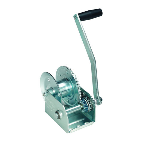
Atlantic Products EMW1500R User manual

Electric
Marine
Winch
Installation instructions
and operating manual
for Atlantic Electric
Marine Winches series.
PLEASE READ CAREFULLY BEFORE OPERATING THE WINCH
EMW1500R
EMW3000R

Atlantic Electric Marine Winches are
portable units designed for intermittent-
duty applications. They are built for
multi-purpose hauling and pulling
operations.
They are not to be used as hoists for lifting,
supporting, or transporting people, or for
handling loads over areas where people
could be present.
These electric winches feature Power-
in, Power-out, controlled freewheeling,
automatic brake and a hand held remote
switch with 10’cord, equipped with 15
metres x 5mm Atlantic Rope cable.
Electric Winch Rating
For intermittent use only. Ratings shown in
graph are based on 10’ continuous pull. For
longer pulls at capacity occasional motor
cooling periods should be allowed.
CAUTION: Continuous running in
excess of 4 minutes will damage
winch motor.
Double Line Operation
Double Line operation increases the pulling
capacity of the winch as shown below;
however, care must be taken to allow
adequate motor cooling. A pulley block
(not supplied) is required for Double Line
operation.
Length of cable on reel (ft)
EMW3000R Double line
EMW1500R
EMW3000R
About the Winch
275
200
76.235
8430
31.75
31.75
222
35
LINE SPEED AND MOTOR CURRENT (FIRST LAYER)
Line pull Line speed Motor current
(lbs / kgs) (FPM / MPM) (Amps)
0 / 0 10.1 / 3.1 10
500 / 227 9.5 / 2.9 20
1000 / 454 8.8 / 2.7 45
1500 / 681 8.2 / 2.5 65
LINE PULL AND CABLE CAPACITY
Layer Rated line pull Cable capacity
of cable per layer (lbs / kgs) (Ft/M)
1 1500 / 681 5.8 / 1.8
2 1228 / 557 12.3 / 2.7
3 1039 / 471 19.3 / 5.9
4 900 / 409 25 / 7.6
5 - -
6 - -
7 - -
EMW1500R SPECIFICATIONS
LINE SPEED AND MOTOR CURRENT (FIRST LAYER)
Line pull Line speed Motor current
(lbs / kgs) (FPM / MPM) (Amps)
0 / 0 3.28 / 1 8
1000 / 454 2.95 / 0.9 15
2000 / 908 2.62 / 0.8 38
3000 / 1362 2.5 / 0.75 65
EMW3000R SPECIFICATIONS
LINE PULL AND CABLE CAPACITY
Layer Rated line pull Cable capacity
of cable per layer (lbs / kgs) (Ft/M)
1 3000 / 1362 4.9 / 1.5
2 2400 / 1070 11.2 / 3.4
3 2010 / 913 18.4 / 5.6
4 1726 / 784 27.1 / 8.3
5 1512 / 686 37.1 / 11.3
6 1345 / 611 47.7 / 14.5
7 1211 / 550 50 / 15.2
2

Mounting of the Winch
MOUNTING INSTRUCTIONS
1. Be sure that the mounting surface is of
sufficient strength to support a load well
in excess of the rated winch capacity.
2. Fasten the winch to the mounting surface
with three 1⁄2” bolts, nuts, washers and
lockwashers. Be sure that the winch is
positioned so that the cable does not rub
the front opening of the winch.
3. For double line use (see Figure 3), install
an eye hook on the winch stand close to
the base of the winch for fastening the
stationary cable hook from pulley block
(not supplied) Be sure the eyehook is
of sufficient strength to withstand loads
in excess of the single line rating of the
winch.
Figure 3
4. Winch is equipped with keyhole slots in
the base for use with quick mounting
shoulder studs, if desirable..If you wish
to use quick mount studs, they should be
mounted securely into the winch stand.
After positioning the winch on the studs,
a 3/8”bolt should be placed in one of the
other holes available to keep the winch
securely in position.
5. Confirm that the winch is positioned so
that the hook or pulley block will not be
drawn into the drum and the cable will
not rub the front opening. Do not reverse
the direction cable if wound on drum.
WIRING HARNESS INSTALLATION
The wiring harness is designed to be
permanently installed on a vehicle and
stored in the trunk or truck bed, etc. This
prevents tampering, accident or misuse of
the winch since the harness is needed to
operate the winch electrically.
The wiring harness can be made re movable
from the vehicle with the Electrical Quick
Connect(see parts list to order).
1. Feed positive lead (long) wire only
through any convenient access hole
inside the car trunk. It may be necessary
to remove a knockout plug or rubber
grommet from the trunk floor. It may
also be necessary to remove the circuit
breaker assembly from the positive wire
in order to feed the wire under the car.
2. Pull the positive lead wire along the
underside of the car into the engine
compartment and up to the battery.
3. Fasten the circuit breaker to the
positive(+)battery terminal(if nut and
bolt type )or to the battery side of the
starter solenoid.
Figure 4 - Base Hole Pattern-Model
EMW1500R & EMW3000R (in mm)
4. Attach negative wire to vehicle frame
using a 1/4”bold and locknut. Make sure
you have a clean, tight connection.
5. Fasten the wire to the car undercarriage
with existing wiring clamps and brackets,
(or plastic wire ties as needed)making
sure wire is not located near the exhaust
system, or any hot or moving parts. Wire
should be fastened securely and without
slack. Excess wire should remain in the
trunk.
NOTE: If winch is to be mounted in
front of vehicle, cut the harness to
the length needed. If spliced, make
sure the splice is tight and well
insulted. Attach ground as described
in 4 above.
30
35
15.8
15.8
76.2
257
51
110.5
31.75
31.75
31.75
84
19.8 type 3
13.5
type 3
10.3 type 2 12.7 tooling hole
3

Unloading and loading under power
1. Attach the power supply plug into the
connector located at the back of the
winch. This plug pushes and snaps into
place easily and will fit in only one
direction. Connect the remote switch cord
to the short cord coming from the back of
the winch. Leave the car engine running
on fast idle as a precaution in case the
battery is not in top condition.
Figure 5
2. With the clutch lever in the engaged
gears position, you may power the winch
in either the load or unload direction.
Allowing the switch to return to the OFF
position will automatically stop the winch
and lock the load in position.
NOTE: It is normal for smoke to be
produced during the initial power out
use.
WARNING: Even though the winch
is equipped with circuit breaker
overloaded protection, particular
care should be taken not to create
an overload. Pay attention to the
sound of the winch and the load
being pulled. Make certain that the
cable tension does not rise suddenly
because of a bind in the load.
CAUTION: The electric motor is
designed for intermittent service
only. Extended use without cooling
off periods will cause overheating
resulting in motor damage.
Maximum recommended continuous
run time is four minutes.
3. When the winching operation is
complete, always secure the load with
appropriate tie down straps or chains.
When the load is being transported on
a trailer, it is advisable to relieve the
tension on the winch cable to avoid
damage to the winch and trailer due
to high shock loads encountered when
traveling.
4. Always disconnect the switch when the
winching operation is complete. Never
leave the switch connected to the winch
when not in use
Operating the clutch
1. The clutch lever provides a means for
releasing a load without power while
maintaining control of the speed, and
provides for free wheeling so that cable
can be removed from the winch by hand.
The clutch lever is spring loaded so that
it returns to the engaged position when
released. The lever will, however, remain
in the free wheeling position if rotated
completely forward to free wheel.
2. In order to release a load without
power, rotate the clutch lever slowly
and carefully forward toward” Free
Wheel.”When the load begins to move, it
can be controlled by the clutch lever will
provide smooth control of the load.
WARNING: Always maintain control
of the load. Allowing excess speed
could result in winch damage and
severe personal injury.
3. Remember that the gear train and brake
mechanism are completely disengaged
in the “Free Wheel” position and in order
to power the winch or hold a load in
position, the lever must be allowed to
return to the “Engaged gears”position.
NOTE: It is not necessary to turn the
clutch lever completely to the “Engaged
Gears” position manually. The spring
tension built into the winch provides
adequate force on the clutch lever.
CAUTION: Never force clutch lever in
either direction.
Auxiliary Handle
1. An emergency crank handle is provided.
For use in the event of a power failure,
Remove the electrical power from the
winch.
2. Remove the plastic plug from the side of
the winch housing and insert the handle
so that it completely engages with the
drive shaft. The handle can be cranked
in either direction with the clutch in
the engaged position. To make cranking
easier, the clutch can be placed in the
free wheel position while holding onto
the emergency handle.
WARNING: If the clutch is placed
in free wheel for hand cranking,
be sure to maintain a firm grip on
the handle at all times. If handle is
released, it will spin violently. Do not
lose control.
Because the emergency crank handle
for Model EMW3000R attaches to the
clutch side of the winch, it is equipped
with a spring operated clip which will
be depressed by the clutch handle in
the free wheel position when cranking
in a clockwise direction to retrieve the
cable. This clip is a safety feature and will
re-engage the clutch mechanism in the
event that the operator loses control of
the handle with a load on the winch.
Figure 6 - Emergency Handle Illustration
WARNING: Even with this safety
feature the handle will still spin
violently one or two turns before
re-engaging the clutch to stop the
winch. Do not lose control.
3. Always remove the handle from the
winch after use and replace the plastic
plug.
Operating the Winch
4

Maintenance of the Winch
Inspect winch a minimum of once
annually. If used more than once a week,
or in adverse conditions, such as salt
water areas or areas of extreme dust
and dirt, more frequent inspection is
required.
1.Carefully inspect the winch cable for
any kinks, frays, or abnormal stiffness
and replace at the first sign of damage.
Lubrication with light oil will improve the
life of the cable.
2. To replace the winch cable, it is necessary
to remove the winch cover.
a. Remove the two clutch handle screws
and the handle, and the four cover
mounting screws.
WARNING: Be sure that the power is
disconnected from the housing.
b. Lift the housing off the winch by gently
stretching it open near the lower front
corners.
c. Rotate the winch reel so theat you have
access to the rope clamp.
d. Remove the old cable and replace it
with a new cable of the same size and
type.
e. Be sure that the cable passes under
both sides of the rope clamp and that
the clamp is tightened securely.
NOTE: Cable is wound under the drum on
Model EMW1500R and EMW3000R.
Figure 7 - Cable Attachment Methods
3. With the cover removed as described
above, inspect the entire gear train and
all drive shafts for any abnormal wear or
loose bearing fits.
a. Grease all of the gears on the inside of
the winch base and apply a drop of oil
on all of the bearings in the base.
b. Very sparingly oil all of the bearings in
the clutch mechanism and place a drop
of oil on the roller clutch.
WARNING: Do not over lubricate
these areas and do not use grease in
the roller clutch. The clutch pad on
clutch gear assembly, brake pads and
brake disc must be kept clean and
oil free.
4.Check the operation of the roller clutch
by carefully rotating the brake disc and
observing the motor shaft.
a. When the disc is turned clockwise, the
motor shaft should turn with it.
b. When the disc is turned
counterclockwise the motor shaft
should not turn.
5. Check all nuts, bolts, retaining rings, etc.,
to be sure that they are tight and secure.
6. If the clutch has been slipping and
requires adjustment, the following
procedures should be used.
NOTE: The clutch is adjustable in ten
degree increments.
a. With a screwdriver and pliers, remove
the end of the clutch spring from the
hole in the winch base.
NOTE: The spring tension is quite high so
be careful to maintain a firm grip on the
spring.
b. Rotate the O-ring so that cutout
portions align with the lugs on the
spring keeper.
c. Expand the ring with a pencil or similar
object and lift the spring keeper free
from the clutch nut.(See Figure 8).
Figure 8 - O-Ring Illustration
d. Rotate the spring keeper clockwise
10 degrees and install on the next
serration in the clutch nut.
e. Reinstall O-ring and rotate slightly so
the cut-outs are not in line with the
lugs on the spring keeper. Reinstall the
clutch spring into the hole in the base
(adjustment of the clutch more than 10
to 20 degrees should normally not be
necessary).
Figure 9 - Clutch Spring Illustration
f. With only the spring pressure, the
spring lug on the spring keeper should
come to rest at approximately the 2:30
o’clock position.(See Figure 9).
NOTE: Do not forcibly tighten the clutch
mechanism.
5

No. Part description Qty
1 Motor assembly 1
2 Brake disc 1
3One-way bearing 16×Ф9.5×13 1
4 Nylon-ring 1
5Bushing 1 1
6 4th stage pinion assembly 1
7Retaining ring Ф16 1
8 Bushing 3 2
9Retaining ring Ф16 2
10 2nd stage gear shaft 1
11 Bushing 1 1
12 2nd stage gear wheel 1
13 Toggle switch 1
14 Hexagon nut with flange M10 1
15 One-way thrust ball bearing
Ф12×Ф26×7.5 1
16 2nd stage coupling 1
17 2nd stage pinion assembly 1
18 Drawn cup needle roller bearing 1
19 1st stage gearwheel 1
20 Clutch spring washer 1
21 Drawn cup needle roller bearing 1
22 Needle roller thrust bearing 2
No. Part description Qty
23 Clutch handle nut 1
24 Clutch spring keeper 1
25 Snap joint 1
26 Clutch handle 1
27 cross recess pan head screw
M3×25 2
28 Clutch spring 1
29 Brake assembly 2
30 1st stage pinion 1
31 Fixed washer 1
32 Check ring 1
33 Long spacer 3
34 Mounting base 1
35 Hexagon screw with flange
M6×12 2
36 Retaining ring Ф12 1
37 Drum shaft 1
38 Flate washer 2
39 Drawn cup needle roller bearing 2
40 Drum 1
41 Hex nut 1
42 Cable clamp kit 1
43 Step bolt 1
No. Part description Qty
44 Front plate 1
45 Hexagon screw with flange 3
46 Cover 1 1
47 Cover 2 1
48 Cross recess pan head screw 1
49 Handle 1
50 Hex nut 3
51 Synthetic rope 1
52 1/4 Hook 1
53 Mounting plate 1
54 Remote control 1
55 Switch socket 1
56 Connector housing 1
57 Quick connector 1
58 Circuit breaker assembly 1
59 Cross recess pan head screw 2
60 Relay assembly 2
61 protecting cover 1
62 Hexagon thin nut 2
63 Hexagon screw with flange 2
64 Hexagon screw with flange 2
65 Round pin 4
Electric Marine Winch Repair Parts List
6

Troubleshooting and General Safety Guide
Symptom Possible Cause(s) Corrective Action
Safety hook spreads 1. Point loading of hook
2. Load exceeds rated capacity of unit
1.Replace hook
2. Lighten load, reduce % of incline or reduce load friction
Cable snaps 1. Improperly maintained cable
2.Overloading
1. See “Maintenance”
2. Reduce load
Cable miswrap and/or crushing Loose cable being wound onto drum Keep tension on cable at all times
Load creeps when power is OFF 1. Brake/clutch out of adjustment
2. Roller clutch not engaging
3. Overloading
4.Cable wound on drum wrong direction
1. Adjust(see “Maintenance”)
2. Replace
3. Reduce load
4. Correct cable winding (See Figure 7)
Winch motor runs but fails
to wind cable
Clutch is slipping or gear
train is damaged
Check clutch lining for grease or oil.
See “Maintenance” for clutch adjustment procedure
Winch motor runs hot In operation too long Let motor cool for at least 20 minutes
(See Winch Rating Section)
Winch motor fails to run Electrical Check the following: power supply, wiring, control switch,
male/female connections and motor
Cable will not pull out
(free wheel)
1.Sticking cable
2.Sticking clutch
1.Avoid cable miswrap
2. a) “Jop” power switch with clutch in free wheel
(No Load Only)
b) Dissemble, clean and readjust
WARNING: Failure to read and follow
instructions could result in serious or
fatal injury. Not to be used as a hoist
for lifting, supporting or transporting
people or loads over areas where
people could be present.
This winch is not designed for movement of
human beings. Do NOT use for scaffolding,
elevators, or any other application in which
persons could be positioned on or under
the load at any time. Do NOT use as an
overhead hoist.
This electric winch should be respected as
power equipment. High forces are created
when using a winch, creating potential
safety hazards. NEVER allow children
or anyone who is not familiar with the
operation of the winch to use it.
Inspect cable before each use. Replace
immediately if damaged or worn.
NEVER exceed rated winch load.
Dangerously high forces can be created
if the load being moved is too large or is
allowed to get in a bind, etc. Note that
installing longer than normal cable results
in increased load on winch. If overloaded
this winch has power enough to break
the cable. Winch is equipped with a high-
quality fibre rope capable of handling the
rated winch load. Never exceed the rated
capacity.
NEVER apply load to winch with the cable
fully extended. Keep at least three turns of
cable on the reel.
Keep the winching area free of all
unnecessary personnel. NEVER stand
between load and winch.
When winching operation has been
completed, do NOT depend on the winch to
support the load. ALWAYS secure the load
properly. Use tie-down straps or chains.
The auxiliary handle is provided for
emergency use only. NEVER use the
auxiliary handle as an assist to the motor
when the motor is running. ALWAYS remove
the auxiliary handle when ti is not in use.
Do NOT operate the winch motor or allow
the handle installed.
The 12 volt DC winch operates from a low
voltage DC source of power(e.g.,a car or
truck battery).Do NOT connect winch to
115V AC power.
Keep hands and fingers clear of the
drum and cable area of the winch when
operating. Do NOT attempt to guide the
cable by hand as it rewinds on the drum.
The winch must be securely attached to a
structural member or frame that is capable
of sustaining loads in excess of the winch
capacity. When attaching the winch to a
vehicle, make sure the mounting pad area
is rigidly supported by the vehicle frame.
ALWAYS block the wheels to prevent vehicle
from rolling when pulling a load with the
winch.
When releasing a load with the clutch,
maintain control of the speed. Excess speed
could result in winch damage and severe
personal injury.
7

ANOTHER QUALITY ATLANTIC PRODUCT
www.atlanticproducts.com.au
This manual suits for next models
1
Table of contents
Other Atlantic Products Winch manuals
Popular Winch manuals by other brands

Hurley Marine
Hurley Marine H30 Instruction manual & safety warnings

Ramsey Winch
Ramsey Winch PATRIOT 9500 UT owner's manual

Warn
Warn 99963 user guide

Badland
Badland APEX 57535 Owner's manual & safety instructions

Dutton-Lainson
Dutton-Lainson DL400 manual

Ramsey Winch
Ramsey Winch RPH 53,3 Operating, Service and Maintenance Manual