Badland Winches 68146 User manual

ATV/UTV Winches
Installation and Operating Instructions
2,000 lb.
Model68146
3,000 lb.
Model68145
5,000 lb.
Model68144
Read this Operator’s Manual carefully before using this tool. Failure to understand and follow the
contents of this manual may result in electrical shock, fire and/or serious personal injury.
When unpacking, make sure that the product is intact and undamaged. If any parts are missing
or broken, please call Harbor Freight Tools at 1-800-444-3353 as soon as possible.
Visit our website at: http://www.harborfreight.com
Copyright
©
2010 by Harbor Freight Tools
®
. All rights reserved. No portion of this manual or any artwork contained herein may be reproduced in any shape
or form without the express written consent of Harbor Freight Tools. Diagrams within this manual may not be drawn proportionally. Due to continuing
improvements, actual product may differ slightly from the product described herein. Tools required for assembly and service may not be included.
Manual Revised 11j
Brought to You by www.snapwhole.com

This page intentionally left blank.
Brought to You by www.snapwhole.com

Page 3For technical questions, please call 1-800-444-3353.ATV Winch
68146 2,000 lb. Winch Specifications
Rated Single
Line Pull
2,000 lb. (907 kg.)
Application Utility/Shop/ATV
Motor 12VDC 1 HP Permanent Magnet
Power IN &
Power OUT Yes
Duty Cycle Rating 5% (45 sec at Max Rated Load;
14 min, 15 sec Rest)
Handlebar Controller Wired, 7 ft (2.1m) long
Geartrain Planetary
Gear Ratio 153:1
Freespool Yes
Brake Auto. Load Holding Dynamic
Drum (Dia. X L) 1.25″ X 2.8″ (32mm X 71mm)
Hook 1/4″ Eye Hook
Fairlead Roller with nylon bushings
Sound Rating 85 dB
Wire Rope
Size / Type
Ø5/32″ x 50′ (Ø4mm X 15.2m)
Nominal strength=2,800 lb
7X19 Galvanized Steel
Aircraft Wire Rope
Battery 12VDC, Minimum 12 Ah
Battery Cables 10 gauge, 5.8′ (1.78m) long
Mounting Pattern 3.15″ (80mm)
Mounting Hardware Winch: 2x G8, M8-1.25 X 35mm
Fairlead:
2x G8, M8-1.25 X 19mm
Overload Protection In line Circuit Breaker
Overall Dimensions
(L X D X H)
11.25″ X 3.88″ X 4.25″
(286 X 99 X 108mm)
Weight 14.7 lb. (6.7 kg.)
IP Rating IP 65 - Winch and Controls
(resistant to water jets)
Winch Certification CE
Layer Rated Line Pull Wire Rope Capacity
12000 lb. (907 kg.) 6′ (1.8m)
2 1635 lb. (742 kg.) 13.7′ (4.2m)
3 1385 lb. (628 kg.) 22.5′ (6.9m)
41200 lb. (544 kg.) 32.8′ (10m)
51055 lb. (479 kg.) 44.5′ (13.6m)
6950 lb. (431 kg.) 50′ (15.2m)
First Layer of Wire Rope Performance
1
Line Pull lb. (kg.) Line Speed fpm (mpm) Amp Draw (@ 12V)
0 (0) 13.3 (4.1) 10
500 (227) 10.8 (3.3) 30
1000 (454) 8.3 (2.5) 55
1500 (680) 6.2 (1.9) 80
2000 (907) 4.1 (1.2) 106
Brought to You by www.snapwhole.com

Page 4 For technical questions, please call 1-800-444-3353. ATV Winch
68145 3,000 lb. Winch Specifications
Rated Single
Line Pull
3,000 lb. (1,361 kg.)
Application ATV/UTV
Motor 12VDC 1 HP Permanent Magnet
Power IN &
Power OUT Yes
Duty Cycle Rating 5% (45 sec at Max Rated Load;
14 min, 15 sec Rest)
Pendant Controller Wired, 12 ft (3.7m) long
Handlebar Controller Wired, 8 ft (2.4m) long
Geartrain 3-Stage Planetary
Gear Ratio 136:1
Freespool Cam Activated
Brake Auto. Load Holding Mechanical
Drum (Dia. X L) 2″ x 2.9″ (50mm x 74mm)
Hook 1/4″ Clevis, with Spring-loaded
Safety Latch
Fairlead Roller with nylon bushings
Wire Rope
Size / Type
Ø3/16″ x 50′ (Ø4.8mm X 15.2m)
Nominal strength=4,200 lb
7X19 Galvanized Steel
Aircraft Wire Rope
Battery 12VDC, Minimum 12 Ah
Battery Cables 6 gauge, 6′ (1.83m) long
Solenoid Cables 6 gauge, 3′ (0.92m) long
Mounting Pattern 3″ x 4.88″ (76.2mm x 124mm)
Mounting Hardware Winch:
4x G8, M8-1.25 X 25mm
Adaptor Plate:
2x G8, M8-1.25 X 25mm
Fairlead:
2x G8, M8-1.25 X 20mm
Socket Lead:
2x G8, ST-M4 X 30mm
Overload Protection In line Circuit Breaker
Sound Rating 85 dB
Overall Dimensions
(L X D X H)
13.3″ X 4.25″ X 4.5″
(338 X 108 X 114mm)
Weight 25 lb. (11.3 kg.)
IP Rating IP 67 - Winch and Controls
(except remote switch,
resistant to immersion up to 3′)
Winch Certification CE
Layer Rated Line Pull Wire Rope Capacity
1 3000 lb. (1361 kg.) 8′ (2.4m)
2 2600 lb. (1179 kg.) 17.3′ (5.3m)
32250 lb. (1021 kg.) 28′ (8.5m)
41990 lb. (903 kg.) 41′ (12.5m)
5 1790 lb. (812 kg.) 50′ (15.2m)
First Layer of Wire Rope Performance
1
Line Pull lb. (kg.) Line Speed fpm (mpm) Amp Draw (@ 12V)
0 (0) 23 (7) 20
1000 (454) 13.1 (4) 81
2000 (907) 11 (3.4) 135
3000 (1361) 6.6 (2) 205
Brought to You by www.snapwhole.com

Page 5For technical questions, please call 1-800-444-3353.ATV Winch
68144 5,000 lb. Winch Specifications
Rated Single
Line Pull
5,000 lb. (2268 kg.)
Application ATV/UTV
Motor 12VDC 1.5 HP
Permanent Magnet
Power IN &
Power OUT Yes
Duty Cycle Rating 5% (45 sec at Max Rated Load;
14 min, 15 sec Rest)
Pendant Controller Wired, 12 ft (3.7m) long
Handlebar Controller Wired, 8 ft (2.4m) long
Geartrain 3-Stage Planetary
Gear Ratio 136:1
Freespool Cam Activated
Brake Auto. Load Holding Mechanical
Drum (Dia. X L) 2″ x 4.7″ (50mm x 120mm)
Hook 1/4″ Clevis, with Spring-loaded
Safety Latch
Fairlead Roller with nylon bushings
Wire Rope
Size / Type
Ø1/4″ x 50′ (Ø6.3mm X 15.2m)
Nominal strength=7,000 lb
7X19 Galvanized Steel
Aircraft Wire Rope
Battery 12VDC, Minimum 12 Ah
Battery Cables 6 gauge, 6′ (1.83m) long
Solenoid Cables 6 gauge, 3′ (0.92m) long
Mounting Pattern 3″ x 6.6″ (76.2mm x 167.6mm)
Mounting Hardware Winch:
4x G8, M8-1.25 X 25mm
Adaptor Plate:
2x G8, M8-1.25 X 25mm
Fairlead:
2x G8, M8-1.25 X 20mm
Socket Lead:
2x G8, ST-M4 X 30mm
Overload Protection In line Circuit Breaker
Sound Rating 85 dB
Overall Dimensions
(L X D X H)
15.8″ X 4.6″ X 4.7″
(400 X 116 X 119mm)
Weight 33 lb. (15 kg.)
IP Rating IP 66 - Winch and Controls
(except remote switch,
resistant to powerful water jets)
Winch Certification CE
Layer Rated Line Pull Wire Rope Capacity
1 5000 lb. (2268 kg.) 50′ (15.2m)
2 4080 lb. (1851 kg.) 36.1′ (11m)
3 3450 lb. (1565 kg.) 22′ (6.7m)
4 2985 lb. (1354 kg.) 9.8′ (3m)
First Layer of Wire Rope Performance
1
Line Pull lb. (kg.) Line Speed fpm (mpm) Amp Draw (@ 12V)
0 (0) 20.5 (6.2) 30
1000 (454) 16.1 (4.9) 83
2000 (907) 12.8 (3.9) 136
3000 (1361) 10.7 (3.3) 168
4000 (1814) 8.6 (2.6) 232
5000 (2268) 6.1 (1.9) 296
Brought to You by www.snapwhole.com

Page 6 For technical questions, please call 1-800-444-3353. ATV Winch
Save This Manual
Keep this manual for the safety warnings and precautions,
assembly, operating, inspection, maintenance and
cleaning procedures. Write the product’s serial
number in the back of the manual near the assembly
diagram (or month and year of purchase if product
has no number). Keep this manual and the receipt
in a safe and dry place for future reference.
Important Safety Information
Symbol Definitions
In this manual, on the labeling, and all other
information provided with this product:
This is the safety alert symbol. It is
used to alert you to potential personal
injury hazards. Obey all safety
messages that follow this symbol to
avoid possible injury or death.
DANGER indicates a hazardous situation which, if
not avoided, will result in death or serious injury.
WARNING indicates a hazardous situation which, if
not avoided, could result in death or serious injury.
CAUTION, used with the safety alert symbol,
indicates a hazardous situation which, if not
avoided, could result in minor or moderate injury.
NOTICE is used to address practices
not related to personal injury.
CAUTION, without the safety alert symbol, is used
to address practices not related to personal injury.
Brought to You by www.snapwhole.com

Page 7For technical questions, please call 1-800-444-3353.ATV Winch
Symbol Property or Statement
Wear heavy-duty, cut- and
abrasion-resistant leather gloves.
Wear ANSI-approved safety glasses.
Cut or sever hazard.
Roller entanglement hazard.
Hot surface burn hazard.
Fire hazard.
Caustic chemical (acid) hazard.
Explosion hazard.
Do not loop the wire rope around
object and hook onto itself.
Do not place finger(s) through hook.
Fingers may be caught and get
pulled into fairlead or drum.
Pull hook using strap only.
Do not use winch in overwind orientation.
(Wire rope enters/exits at the top.)
Use winch only in underwind orientation.
(Wire rope enters/exits at the bottom.)
Symbol Property or Statement
VDC Volts Direct Current
AAmperes
CCA Cold Cranking Amperes
HP Horsepower
fpm Feet Per Minute
mpm Meters Per Minute
RPM Revolutions Per Minute
IP
International Protection rating
Classifies the degrees of protection provided
against the intrusion of solid objects,
dust, accidental contact, and water.
G8 Grade 8
A fastener strength rating.
WARNING! Read all instructions.
Failure to follow all instructions listed
on pages 8 to 11 may result in fire,
serious injury and/or DEATH.
The warnings and precautions discussed in this
manual cannot cover all possible conditions and
situations that may occur. It must be understood
by the operator that common sense and caution
are factors which cannot be built into this
product, but must be supplied by the operator.
Brought to You by www.snapwhole.com

Page 8 For technical questions, please call 1-800-444-3353. ATV Winch
Installation Precautions
1. Do not wear loose clothing or jewelry,
as they can be caught in moving parts.
Non-skid footwear is recommended.
Wear restrictive hair covering to contain long hair.
2. Wear ANSI-approved safety goggles and heavy-duty
leather work gloves during installation.
3. Before installation confirm that area is clear
of fuel lines, brake lines, electrical wires,
gas tanks or any other component which
could be damaged during drilling.
4. Mounting location and hardware
must support winch and load.
5. Use supplied power cords and wire rope listed
in manual only. Do not use thinner/longer
cables or link multiple cables together.
6. Do not route electrical cables near sharp edges
or parts that will move or become hot.
7. Ventilate area well before and while working
on battery. Explosive invisible hydrogen gas
can accumulate and then explode when ignited
by a spark from the battery connection.
8. Only connect to a clean, corrosion free battery.
9. Do not lean over or come in contact with
battery while making connections.
10. Remove all metal jewelry before working near battery.
11. Connect red wire to positive battery terminal
and black wire to negative battery terminal.
12. Insulate all exposed wiring and
terminals after installation.
13. Install winch and fairlead in underwind orientation,
so that the wire rope enters and exits the
winch at the bottom of the drum.
Brought to You by www.snapwhole.com

Page 9For technical questions, please call 1-800-444-3353.ATV Winch
Operation Precautions
1. Do not exceed load capacity. Be aware of
dynamic loading! Sudden load movement may
briefly create excess load causing product failure.
2. Do not maintain power to the winch if the
motor stalls. Verify load is within rated capacity
for the wire rope layer, see Winch Specifications
on pages 3 to 5. Make sure the battery is
fully charged. Use double line rigging whenever
possible, see ″Double Line Rigging″ on page 18.
3. Wear ANSI-approved safety goggles and
heavy-duty leather work gloves during operation.
4. Do not disengage clutch under load.
Engage clutch before starting.
5. Keep clear of fairlead when operating.
Do not try to guide wire rope.
6. Do not place finger(s) through hook. Fingers may
be caught and get pulled into fairlead or drum.
Use included strap to hold hook instead.
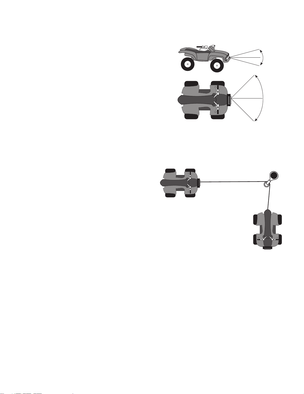
7. Stay out of the direct line that the wire rope is pulling.
If it slips or breaks, it will “whiplash” along this line.
Place heavy rag or carpet over wire rope span 6
feet from hook to help absorb the force released
if the wire rope breaks. (See Figure A.)
FIGURE A — WHIPLASH
DAMPENING BLANKET OR RUG
8. Do not use for lifting or moving people.
9. Use a spotter to assist you in ensuring that it
is safe to operate the winch. Make sure the
spotter is out of the way of the vehicle and
the wire rope before activating the winch.
10. Do not use the hand crank, if equipped,
to “assist” the winch.
11. Do not use vehicle to pull on the Wire Rope
and “assist” the winch.
12. Use as intended only. Do not lift items
vertically or use for aircraft purposes.
13. Prevent entanglement. Do not wear loose clothing
or jewelry, as they can be caught in moving parts.
Non-skid footwear is recommended. Wear restrictive
hair covering to contain long hair.
14. Disconnect battery cables before working
near the Wire Rope, drum, fairlead or
load, to prevent accidental starting.
15. Inspect before every use; do not use if damaged or
parts loose. Examine the winch for structural cracks,
bends, damage, frayed or kinked wire rope, and any
other conditions that may affect the safe operation
of the winch. Do not use the winch even if minor
damage appears. A kink permanently weakens the
wire rope, even after it is straightened out; kinked
wire rope can fail suddenly and must not be used.
16. Keep wire rope straight to avoid kinking the wire rope.
The illustrations below show how a kink
forms and how to prevent kinking.
a. This illustration shows a kink about
to form. At this point the winch
should be stopped and the wire
rope should be straightened out to
prevent kinking.
b. This wire rope is
kinked. It is too late
to reverse the
damage at this point, the
wire rope must be discarded.
It is permanently damaged and
must not be used.
c. This is a kinked wire rope that has been
straightened out. Even though it has been pulled
straight, some wires in the wire rope are stretched,
and others are severely bent, if not broken.
The unstretched wires will take more load and can
fail suddenly before the rope reaches its capacity.
This wire rope must be discarded and not be used.
A kink permanently weakens the wire rope,
even after it is straightened out; kinked wire rope
can fail suddenly and must not be used.
Brought to You by www.snapwhole.com

Page 10 For technical questions, please call 1-800-444-3353. ATV Winch
17. Keep children and bystanders away while operating.
Distractions can cause you to lose control.
18. Stay alert, watch what you are doing and use common
sense when operating. Do not use a winch while you
are tired or under the influence of drugs, alcohol or
medication. A moment of inattention while operating
winches may result in serious personal injury.
19. Do not overreach. Keep proper footing and
balance at all times. This enables better control
of the winch in unexpected situations.
20. Hook onto the object using a pulling point,
tow strap or chain. Do not wrap the wire rope
around the object and hook onto the wire rope
itself. This can cause damage to the object
being pulled, and kink or fray the wire rope.
21. Do not use a Recovery Strap while winching.
They are designed to stretch and can suddenly whip
back towards the operator during a winching operation.
22. Secure load after moving.
NO LOCKING MECHANISM.
23. Keep at least 5 full turns of wire rope on drum.
The wire rope’s connection to the drum is not intended
to sustain a load, without the added support from
the friction of at least 5 full turns of wire rope.
24. Wrap wire rope under 500 lb. tension before use.
Otherwise, wire rope may bind during operation.
25. Keep clear of wire rope, hook, and load while winching.
Do not step over wire rope.
Do not push sideways against wire rope
under tension; wire rope might break under
this load and recoil back, striking the person
pushing against it or a bystander.
26. If wire rope begins to get entangled, stop winch
immediately and release wire rope using switch.
27. For 68146 (2,000 lb.) and 68144 (5,000 lb.) winches:
Do not submerge winch in water.
If winch gets submerged accidentally, it needs
to be immediately disassembled, cleaned, dried
and re-lubricated by a qualified technician to
prevent permanent damage from corrosion.
28. Only winch with the winching vehicle′s transmission
in neutral. Winching with a vehicle′s transmission in
gear or park may damage the transmission. A vehicle′s
transmission is not designed to handle that type of load.
29. Do not operate the winch at extreme angles.
Do not exceed the angles shown in Figure B for
a roller fairlead. For a hawse fairlead, the angle
should be as close to straight as possible.
FIGURE B — ROLLER FAIRLEAD
MAXIMUM WINCHING ANGLES
15°
15°
45°
45°
30. If the object to be pulled must be pulled at an angle in
relation to the winch, use a pulley (sold separately) and
an anchor point directly in front of the winch, as shown
in Figure C, to keep the Wire Rope pull straight.
FIGURE C — PULLEY ANCHORING
31. Broken strands of wire rope will be sharp.
Wear heavy-duty work gloves when handling
the wire rope. Do not slide wire rope
through hands, even with gloves on.
32. Winch motor will be hot during and after use.
Keep clear.
33. Do not power the hook all the way
into the fairlead or winch.
34. People with pacemakers should consult their
physician(s) before use. Electromagnetic fields in
close proximity to heart pacemaker could cause
pacemaker interference or pacemaker failure.
Brought to You by www.snapwhole.com

Page 11For technical questions, please call 1-800-444-3353.ATV Winch
Service Precautions
1. Wear ANSI-approved safety goggles and
heavy-duty leather work gloves during service.
2. Disconnect power to winch and allow it
to cool completely before service.
3. Use supplied power cords/wire rope or cables
listed in manual only. Do not use thinner/longer
cables or link multiple cables together.
4. Have the winch serviced by a qualified repair person
using only identical replacement parts. This will
ensure that the safety of the winch is maintained.
5. Maintain labels and nameplates on the winch.
These carry important safety information.
If unreadable or missing, contact
Harbor Freight Tools for a replacement.
6. WARNING: Handling the cord on this product
will expose you to lead, a chemical known to the
State of California to cause cancer, and birth defects or
other reproductive harm. Wash hands after handling.
(California Health & Safety Code § 25249.5, et seq.)
SAVE THESE
INSTRUCTIONS.
Brought to You by www.snapwhole.com

Page 12 For technical questions, please call 1-800-444-3353. ATV Winch
Installation and Setup
Read the ENTIRE IMPORTANT SAFETY
INFORMATION section at the beginning
of this manual including all text
under subheadings therein before
set up or use of this product.
Mounting the Winch
1. The plate must be rated to at least the winch’s capacity.
2. Align the winch perpendicular to center line
of the vehicle at the desired location, and
mark the locations of the winch base holes.
Compare the dimensions of the marked holes to
the section of Figure D that matches your winch.
2*Ø0.33 in. / 8.5mm
3.15 in.
/ 80mm
3.94 in. / 100mm
2 in. /
51mm
8.31 in. / 211mm
11.25 in. / 286mm
Model 68146
2.83 in.
/ 72mm
4.13 in. / 105mm
1.25 in.
/ 32mm
Model 68145
2 in.
/ 51mm
2.83 in.
/ 72mm
4.49 in. / 114mm
4*Ø8mm
(threaded)
4.33 in. / 110mm
3 in. /
76mm
4.88 in. / 124mm 6.3 in. / 160mm
13.35 in. / 339mm
Model 68144
2 in.
/ 51mm
4.72 in. / 120mm
15.55 in. / 395mm
4.72 in. / 120mm
6.61 in. / 168mm5.31 in. / 135mm
4.61 in. / 117mm
3 in.
/ 76mm
4*Ø8.5mm
FIGURE D — WINCH DIMENSIONS
REV 11e
Brought to You by www.snapwhole.com

Page 13For technical questions, please call 1-800-444-3353.ATV Winch
3. Before drilling, verify that the installation
surface has no hidden components or
structural pieces that will be damaged.
NOTE: This winch can generate extreme forces. Select
a location that can withstand the rated capacity without
damage or weakening. Steel reinforcement plates may
be needed or a certified welder may need to weld on
additional bracing depending on the mounting location.
4. Drill holes appropriate for the hardware
at the marked locations.
5. Install the winch using hardware described under
Winch Specifications on pages 3 to 5.
Mounting Winch Components
1. Mount solenoid box, switch controller, and
socket lead in proper locations so that:
a. Winch components are close enough to each
other to allow wires to be routed properly.
b. Vehicle component operation is not interfered with.
c. Vehicle components are not damaged
by drilling or driving screws.
d. Winch components will not be damaged by
stresses caused by vehicle operation.
2. Mark the locations where the screw holes will be.
3. Verify that the installation surface has no
hidden components or structural pieces
that will be damaged before drilling.
4. Drill pilot holes for the mounting screws.
5. Secure in place with mounting screws.
Wiring
TO PREVENT SERIOUS INJURY FROM
EXPLOSION DUE TO SPARKING AT THE
BATTERY CONNECTION:
Disconnect the Battery Cables before
making other wiring connections.
TO PREVENT SERIOUS INJURY FROM
LEAKING BATTERY ACID:
Do not use a dirty, corroded or leaking
battery. Only use a 12V automotive
(or equivalent) battery, in good condition.
1. Plan a route for the wiring from the point of the
vehicle where the winch will be mounted, or
used, to the battery. This route must be secure,
out of the way of moving parts, road debris, or
any possibility of being damaged by operation
or maintenance of the vehicle. For example,
you may wish to route the wires under the vehicle,
attaching it to the frame using suitable fasteners.
Do not attach the wires to the exhaust system,
drive shaft, emergency brake cable, fuel line, or any
other components which may create damage the
wiring through heat or motion, or create a fire hazard.
2. If you drill through the bumper or any part of the body
to route the wires, be sure to install a rubber grommet
in the hole to prevent fraying of the wires at that point.
Brought to You by www.snapwhole.com

Page 14 For technical questions, please call 1-800-444-3353. ATV Winch
3. Route the Cables from the Solenoid to the battery
and from the Solenoid to the Winch, following the
precautions discussed earlier. See Figure E.
Model 68146
Circuit
Breaker
Solenoid
Box
Winch
Black
Black
Green
Black
Red
Red
Red
(to ignition)
Model 68145 and 68144
Red
(to ignition)
Circuit
Breaker
Solenoid
Box
Winch
Black
Blue
Black
Black
White
Green
Red
Red
Yellow
Red
FIGURE E — WIRING CONNECTIONS
4. Attach the wires from the solenoid to
the terminals on the Winch.
5. Attach the Circuit Breaker to the
Positive Terminal on the battery.
6. Attach the red Battery Cable to the Circuit Breaker.
7. Attach the black Battery Cable directly to
the negative terminal of the battery.
8. Wire in the Switch Controller
(and Socket Lead, if equipped)
according to the diagrams on the facing page.
9. The cable leading from the Switch Controller
has a red wire extending out from its
side. Connect this to an ignition circuit
(switched by the vehicle′s key) to help prevent
accidental starting. The winch will not operate
if that wire is not properly connected.
a. Use a circuit tester to find a wire that energizes
when the vehicle′s key is turned to on, and
turns off when the key is turned to off.
b. That is an ignition controlled wire.
c. Connect wire shown in Figure F to that wire.
FIGURE F — WIRING TO VEHICLE′S KEYED IGNITION
Red
(to ignition)
Switch
Controller
Note: If not attaching the winch to a vehicle,
attach the ignition wire to the positive battery terminal.
IF THIS IS NOT DONE,
THE WINCH WILL NOT OPERATE.
Note: The attachment of the Motor Cables
determines the operation of the Controller’s button.
After the unit is mounted and powered,
check the direction of the Power In and Power Out on
the Controller button. If you wish to change the direction
on the Controller, disconnect the Battery Cables from
the battery, switch the Motor Cable connections on the
Motor Assembly, then reconnect the Battery Cables.
REV 10l
Brought to You by www.snapwhole.com

Page 15For technical questions, please call 1-800-444-3353.ATV Winch
Preparing the Wire Rope
1. The wire rope must be properly coiled under tension
to be able to support a load without damage.
2. Uncoil the wire rope, except for 5 full wraps.
3. Recoil the wire rope back into the winch
under at least 500 lb. of tension.
REV 10l
Brought to You by www.snapwhole.com

Page 16 For technical questions, please call 1-800-444-3353. ATV Winch
Operation
Read the ENTIRE IMPORTANT SAFETY
INFORMATION section at the beginning
of this manual including all text under
subheadings therein before set up or
use of this product.
The instructions that follow are basic
guidelines only and cannot cover all
situations encountered during use. The
operator and assistants must carefully
plan usage to prevent accidents.
Clutch Operation
ITEM 68146, 2000 lb. Winch:
1. The position of the pin in the shaft determines
whether the clutch is engaged or not.
Shaft
Pin
Drum
End
If the pin rests
in the groove in the drum
the clutch is engaged.
Shaft
Pin
Drum
End
If the pin rests
on top of the end of the drum
the clutch is released.
2. To change clutch positions (see Figure G):
a. Pull clutch knob out.
b. Turn it 90° while it is pulled out, then release it.
a
b
FIGURE G — 68146 CLUTCH OPERATION
ITEM 68145, 3000 lb. Winch and
ITEM 68144, 5000 lb. Winch:
CAUTION: Do not adjust the clutch unless
there is no load on the wire rope.
1. To engage the clutch, turn the Clutch Knob
clockwise completely until it stops, see Figure H.
2. To release the clutch (freespool), turn the
Clutch Knob counterclockwise completely
until it stops, see Figure H.
FIGURE H — 68145, 68144 CLUTCH OPERATION
Engage
Release
(freespool)
REV 10l
Brought to You by www.snapwhole.com

Page 17For technical questions, please call 1-800-444-3353.ATV Winch
Basic Operation
Note: If a winch is to be used to pull a vehicle,
it should optimally be rated to a single line
pull at least twice the vehicle’s weight.
1. Examine the wire rope. Do not use the winch if
the wire rope is frayed, kinked or damaged.
2. Fully charge the vehicle’s battery.
3. Check the Winch’s electrical connections.
All connections must be tight and clean.
4. Put the vehicle’s transmission in Neutral.
5. If the vehicle where the winch is mounted
is not supposed to be moved, engage the
emergency brake and block the wheels
using wheel chocks (sold separately).
6. To pull out the wire rope, move the Clutch Control to
the Released position, see the instructions for your
winch model under Clutch Operation section, slide the
loop of the Hook Strap over the hook, then pull on the
Hook Strap to pull out the wire rope.
WARNING! Leave at least five full
turns of wire rope on the drum.
7. Hook onto the object using a pulling point,
tow strap, tree strap, or chain. See Figure I.
FIGURE I — USING A STRAP ANCHOR POINT
Do not wrap the wire rope around
the object and hook onto the
wire rope itself.
This can damage the object being pulled,
and kink or fray the wire rope.
8. Attachment point must be centered in
loop of hook and the hook’s safety clasp
must be fully closed. See Figure J.
FIGURE J — CORRECT AND INCORRECT
HOOK ATTACHMENT
9. Do not use a Recovery Strap while winching.
They are designed to stretch and can suddenly whip
back towards the operator during a winching operation.
10. Place a heavy rag or carpet (sold separately) over
the wire rope span, 6 feet from the hook to help
absorb the force released if the wire rope breaks.
FIGURE A — WHIPLASH
DAMPENING BLANKET OR RUG
11. Move the Clutch Control to the Engaged position,
see the instructions for your winch model
under ″Clutch Operation″ on page 16.
WARNING! Do not allow anyone to stand near the
wire rope, or in line with the wire rope behind the
winch while it is under power. If the wire rope should
slip or break, it can suddenly whip back towards
the winch, causing a hazard for anyone in the area.
Stand well to the side while winching.
Brought to You by www.snapwhole.com

Page 18 For technical questions, please call 1-800-444-3353. ATV Winch
Double Line Rigging
a. A double line system should be used whenever
possible. It reduces the load on the winch,
allowing it to work longer with less heat buildup.
It reduces load on the winch in two ways:
• It utilizes the lower layers of wire rope
that have higher capacity, and
• It halves the load on the winch through pulley action.
b. Connect the wire rope for a double line
system as shown in Figure K below.
Use a pulley block (sold separately) properly
rated for the load to be pulled and designed
to be operated with this winch’s wire rope.
FIGURE K — DOUBLE LINE SETUP
Stationary
Winching Vehicle
(Chock tires,
set parking brake,
and leave in neutral) Load
Carpet
c. Loop the wire rope around the pulley and connect
to another part of the vehicle’s chassis or to a
separate anchor point. Do not anchor the Wire
Rope back to the winch or winch mount.
Note: If anchoring the winching vehicle, only attach the
anchor line to the front of the vehicle. If the anchor line
is attached to the rear of the vehicle, the vehicle′s frame
may be damaged by the forces exerted by winching.
12. Operate the controls briefly to
ensure they work properly.
• The IN position should retract the winch cable.
• The OUT position should power out the cable.
If operation is reversed, the power cables
may be connected backwards.
Correct any such issue before use.
13. When it is safe to do so, use the power switch on
the Controller to retract the wire rope, and winch
the item as desired. Do not power the hook all
the way into the fairlead to prevent damage.
14. Do not operate the winch at extreme angles.
Do not exceed the angles shown in Figure B for
a roller fairlead. For a hawse fairlead, the angle
should be as close to straight as possible.
FIGURE B — ROLLER FAIRLEAD
MAXIMUM WINCHING ANGLES
15°
15°
45°
45°
15. If the object to be pulled must be pulled at an angle
in relation to the winch, use a pulley (sold separately)
and an anchor point directly in front of the winch, as
shown in Figure C, to keep the Wire Rope pull straight.
FIGURE C — PULLEY ANCHORING
16. WARNING! Stop the winch and release tension on the
wire rope before moving the rag or carpet placed on it.
17. Do not continue use of the winch until
the battery is completely run down.
18. When possible, keep the engine running while using
this winch, to continually recharge the battery and
prevent the battery from being drained so much that
the vehicle cannot start. However, exercise extreme
caution when working around a running vehicle
and ONLY operate a vehicle in an outdoor area.
Brought to You by www.snapwhole.com

Page 19For technical questions, please call 1-800-444-3353.ATV Winch
CAUTION: Do not use the winch in a
constant duty application, it is designed for
INTERMITTENT USE ONLY. Keep the duration of the
pulling job as short as possible. If the motor becomes
very hot to the touch, stop and let it cool down for
several minutes. Do not pull for more than one minute
at or near the rated load. Do not maintain power to the
Winch if the motor stalls. Double Line Rigging will help
prevent overloading and should be used whenever
practical, see ″Double Line Rigging″ on page 18.
19. When finished pulling the load, reverse the direction
of the winch just enough to release tension on
the Wire Rope so that you can unfasten the Hook
from the load and reel in the Wire Rope.
20. Disconnect the Pendant Controller
(if equipped) after use.
Duty Cycle (Duration of Use)
at least
14 minutes,
15 seconds
of rest
45 seconds winching
Avoid damage to the Winch by not winching
for more than the prescribed duty cycle time.
The Duty Cycle defines the amount of time, within
a 15 minute period, during which a Winch can
operate at its maximum capacity without overheating.
For example, this Winch with a 5% duty cycle at its
maximum load must be allowed to rest for at least
14 minutes, 15 seconds after every 45 seconds of
continuous operation. Failure to carefully observe
duty cycle limitations can easily over-stress a
Winch contributing to premature Winch failure.
Brought to You by www.snapwhole.com

Page 20 For technical questions, please call 1-800-444-3353. ATV Winch
Maintenance and Servicing
Procedures not specifically explained
in this manual must be performed
only by a qualified technician.
TO PREVENT SERIOUS INJURY FROM
ACCIDENTAL OPERATION:
Disconnect the Battery Cables before
performing any inspection, maintenance,
or cleaning procedures.
TO PREVENT SERIOUS INJURY FROM
WINCH FAILURE:
Do not use damaged equipment.
If abnormal noise or vibration occurs,
have the problem corrected before further use.
Cleaning, Maintenance,
and Lubrication
1. BEFORE EACH USE, inspect the general
condition of the winch. Check for loose hardware,
misalignment or binding of moving parts, cracked
or broken parts, damaged electrical wiring,
corroded or loose terminals, and any other
condition that may affect its safe operation.
Examine the wire rope. Do not use the winch if
the wire rope is frayed, kinked or damaged.
2. AFTER USE, wipe external surfaces
of the winch with clean cloth.
3. Lubricate the wire rope occasionally with a light oil.
4. The winch’s internal mechanism is
permanently lubricated. Do not open the housing.
However, if the winch is submerged, it should be
opened, dried, and re-lubricated by a qualified
technician as soon as possible to prevent corrosion.
Wire Rope Replacement
1. Move Clutch Handle to the Released position.
2. Extend the Wire Rope to its full length,
noting how the existing Wire Rope is
connected to the inside of the drum.
3. Remove old Wire Rope and attach new assembly.
CAUTION: Do not replace with inferior Wire Rope.
Only use a wire rope rated to the same rating
cited on the specification chart or better.
4. Retract Wire Rope onto Wire Rope
drum being careful not to allow kinking.
Refer to instructions for tensioning the wire rope
under ″Preparing the Wire Rope″ on page 15.
5. Test Electric Winch for proper operation.
Brought to You by www.snapwhole.com
This manual suits for next models
2
Table of contents
Other Badland Winches Winch manuals
Popular Winch manuals by other brands

Gude
Gude GSZ 100 Translation of original operating instructions

Westin
Westin T-Max REW-9000 Fitting instructions

Ingersoll-Rand
Ingersoll-Rand Force 5i Series Product information

DINAMIC OIL
DINAMIC OIL S20 instruction manual

Ingersoll-Rand
Ingersoll-Rand force 5 FA2 Parts, operation and maintenance manual

Smittybilt
Smittybilt XRC8 installation manual